FANUC0i系统_宏程序
- 格式:ppt
- 大小:768.50 KB
- 文档页数:26
FANUC 0I数控车床的宏程序编制摘要:用户宏程序是提高数控车床性能的一种特殊功能,它是使用变量来代替程序中的功能代码或地址值面编制的加工程序。
这些变量可同因数一样进行逻辑运算,因而可以使复杂的程序大大简化。
关键词:宏程序、宏指令、非圆二次曲线、变量Macro Programming of CNC Lathe with FANUC oi SystemAbetract: User macro programs are special functions to improve the performance of CNC lathe which replaces the functional codes or addresses with variables. These variables can do logical operations like the factors so that they can simplify the complex programs effectively. Keywords:macro program,macroinstruction,non-circular quadratic curves,variable0、引言随着我国机械行业的飞速发展,数控加工技术在机械制造业中得到了越来越广泛的运用,很多企业都引进了数控机床设备。
用户在使用数控机床设备加工工件时,只需按照各种数控编程指令的格式编程即可。
通用的数控系统在处理插补和伺服时都是采用边插补边控制伺服的方式。
由于非圆曲线形状较为复杂,在插补时需要处理的数据量大,同时响应速度的要求较高,因此,一般的数控系统只有直线插补和圆弧插补两种插补功能,并不具备其它曲线的插补功能。
在传统的CNC编程时有时这些指令满足不了用户的要求,入加工椭圆、抛物线、双曲线等,这时就可使用用户宏程序功能,用户可以根据需要自己扩展数控系统的功能。

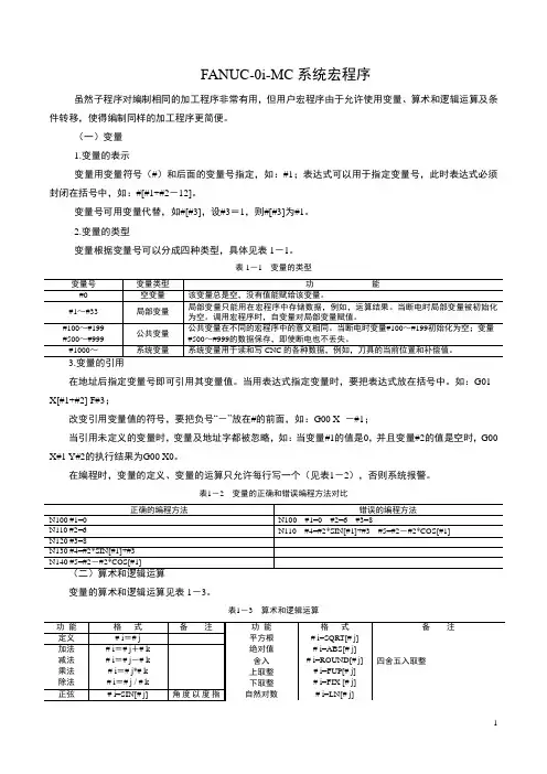
FANUC-0i-MC 系统宏程序虽然子程序对编制相同的加工程序非常有用,但用户宏程序由于允许使用变量、算术和逻辑运算及条件转移,使得编制同样的加工程序更简便。
(一)变量 1.变量的表示变量用变量符号(#)和后面的变量号指定,如:#1;表达式可以用于指定变量号,此时表达式必须封闭在括号中,如:#[#1+#2-12]。
变量号可用变量代替,如#[#3],设#3=1,则#[#3]为#1。
2.变量的类型变量根据变量号可以分成四种类型,具体见表1-1。
表1-1 变量的类型在地址后指定变量号即可引用其变量值。
当用表达式指定变量时,要把表达式放在括号中。
如:G01 X[#1+#2] F#3;改变引用变量值的符号,要把负号“-”放在#的前面,如:G00 X -#1;当引用未定义的变量时,变量及地址字都被忽略,如:当变量#1的值是0,并且变量#2的值是空时,G00 X#1 Y#2的执行结果为G00 X0。
在编程时,变量的定义、变量的运算只允许每行写一个(见表1-2),否则系统报警。
表1-2 变量的正确和错误编程方法对比变量的算术和逻辑运算见表1-3。
表1-3 算术和逻辑运算1.上取整和下取整CNC 处理数值运算时,若操作后产生的整数绝对值大于原数的绝对值时为上取整;若小于原数的绝对值为下取整。
对于负数的处理应注意。
如:#1=1.2,#2=-1.2,则#3=FUP[#1]→#3=2;#3=FIX[#1]→#3=1;#3=FUP[#2]→#3=-2;#3=FIX[#2]→#3=-1。
2.运算次序函数→乘和除运算(*、/、AND )→加和减运算(+、-、OR 、XOR )。
3.括号嵌套括号(方括号)用于改变运算次序。
括号可以使用5级,包括函数内部使用的括号。
圆括号用于注释语句。
如:#1=SIN[[[#2+#3]*#4+#5]*#6] (3重括号) 4.运算符运算符见表1-4。
表1-4 运算符5.(1)# i=ASIN[# j]当参数No.6004#0设为“0”时,90°~270°;当参数No.6004#0设为“1”时,-90°~90°。

本系统宏程序体系采用FANUC系统宏程序B方式实现一变量普通加工程序直接用数值指定G代码和移动距离;例如,GO1和X100.0。
使用用户宏程序时,数值可以直接指定或用变量指定。
当用变量时,变量值可用程序或用MDI面板上的操作改变。
#1=#2+100G01 X#1 F300说明:变量的表示计算机允许使用变量名,用户宏程序不行。
变量用变量符号(#)和后面的变量号指定。
例如:#1表达式可以用于指定变量号。
此时,表达式必须封闭在括号中。
例如:#[#1+#2-12]变量的类型变量根据变量号可以分成四种类型#0-#49 局部变量局部变量只能用在宏程序中存储数据,例如,运算结果.当断电时,局部变量被初始化为0.调用宏程序时,自变量对局部变量赋值,#50-#499 公共变量公共变量在不同的宏程序中的意义相同.当断电时, 公共变量初始化为0.目前版本中,某些公众变量被赋予特殊意义(系统变量),用于描述CNC运行时各种数据的变化,这些变量包括:#449用于指明固定循环退刀模式(G98,G99), 如在G99方式下,#449变量为1;如在G98方式下,#449变量为-1.#450用于指明当前程序段处于绝对坐标编程模式(G90)还是相对坐标编程模式(G91).如在G90方式下,#450变量为1;如在G91方式下,#450变量为-1.#451,#452,#453,#454用于存储刀具当前位置(X,Y,Z,A轴)在后期的版本中,将会安排专门的空间作为系统变量区.变量值的范围局部变量和公共变量在系统内采用浮点数方式存储小数点的省略当在程序中定义变量值时,小数点可以省略。
例:当定义#1=123;变量#1的实际值是123.000。
变量的引用为在程序中使用变量值,指定后跟变量号的地址。
例如:G01X#1+#2F#3或者G01X[#1+#2]F#3限制程序号,顺序号和任选程序段跳转号不能使用变量。
例:下面情况不能使用变量:0#1;/#2G00X100.0;N#3Y200.0;二算术运算和逻辑运算置换#I=#j算术运算加:#I=#j+#k,减:#I=#j-#k,乘:#I=#j*#k,除:#I=#j/#k。
宏程序设计宏程序与子程序类似,对编制相同加工的操作可以使程序简化.同时宏程序中可以使用变量,算术和逻辑运算及转移指令,还可以方便地实现循环程序设计。
使相同加工操作的程序更方便,更灵活。
本章以FANUC系统为例介绍宏程序设计的内容。
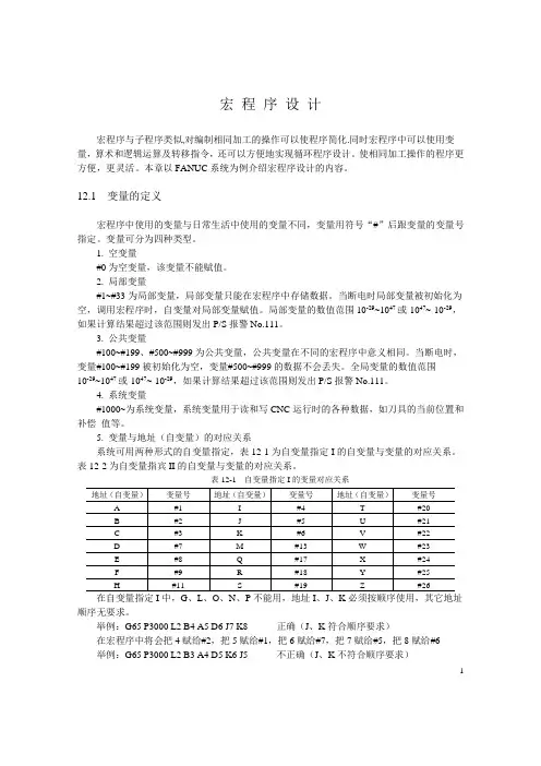
12.1 变量的定义宏程序中使用的变量与日常生活中使用的变量不同,变量用符号“#”后跟变量的变量号指定。
变量可分为四种类型。
1. 空变量#0为空变量,该变量不能赋值。
2. 局部变量#1~#33为局部变量,局部变量只能在宏程序中存储数据。
当断电时局部变量被初始化为空,调用宏程序时,自变量对局部变量赋值。
局部变量的数值范围10-29~1047或-1047~-10-29,如果计算结果超过该范围则发出P/S报警No.111。
3. 公共变量#100~#199、#500~#999为公共变量,公共变量在不同的宏程序中意义相同。
当断电时,变量#100~#199被初始化为空,变量#500~#999的数据不会丢失。
全局变量的数值范围10-29~1047或-1047~-10-29,如果计算结果超过该范围则发出P/S报警No.111。
4. 系统变量#1000~为系统变量,系统变量用于读和写CNC运行时的各种数据,如刀具的当前位置和补偿值等。
5. 变量与地址(自变量)的对应关系系统可用两种形式的自变量指定,表12-1为自变量指定I的自变量与变量的对应关系。
表12-2为自变量指宾II的自变量与变量的对应关系。
表12-1 自变量指定I的变量对应关系地址(自变量)变量号地址(自变量)变量号地址(自变量)变量号A #1 I #4 T #20B #2 J #5 U #21C #3 K #6 V #22D #7 M #13 W #23E #8 Q #17 X #24F #9 R #18 Y #25H #11 S #19 Z #26在自变量指定I中,G、L、O、N、P不能用,地址I、J、K必须按顺序使用,其它地址顺序无要求。
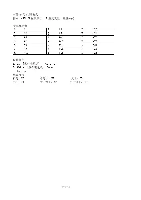
宏程序的简单调用格式:格式:G65 P程序序号 L重复次数变量分配控制命令1.If [条件表达式] GOTO n2.While [条件表达式] DO mEnd m运算符号相等:EQ 不等于: NE 大于:GT 小于:LT 大于等于:GE 小于等于:LEFANUC系统宏程式FANUC系统宏程序编程一变量普通加工程序直接用数值指定G代码和移动距离;例如,GO1和X100.0。
使用用户宏程序时,数值可以直接指定或用变量指定。
当用变量时,变量值可用程序或用MDI面板上的操作改变。
#1=#2+100G01 X#1 F300说明:变量的表示计算机允许使用变量名,用户宏程序不行。
变量用变量符号(#)和后面的变量号指定。
例如:#1表达式可以用于指定变量号。
此时,表达式必须封闭在括号中。
例如:#[#1+#2-12]变量的类型变量根据变量号可以分成四种类型变量号变量类型功能#0 空变量该变量总是空,没有值能赋给该变量.#1-#33 局部变量局部变量只能用在宏程序中存储数据,例如,运算结果.当断电时,局部变量被初始化为空.调用宏程序时,自变量对局部变量赋值,#100-#199 #500-#999 公共变量公共变量在不同的宏程序中的意义相同.当断电时,变量#100-#199初始化为空.变量#500-#999的数据保存,即使断电也不丢失.#1000 系统变量系统变量用于读和写CNC运行时各种数据的变化,例如,刀具的当前位置和补偿值.变量值的范围局部变量和公共变量可以有0值或下面范围中的值:-1047到-10-29或-10-2到-1047如果计算结果超出有效范围,则发出P/S报警NO.111.小数点的省略当在程序中定义变量值时,小数点可以省略。
例:当定义#1=123;变量#1的实际值是123.000。
变量的引用为在程序中使用变量值,指定后跟变量号的地址。
当用表达式指定变量时,要把表达式放在括号中。
例如:G01X[#1+#2]F#3;被引用变量的值根据地址的最小设定单位自动地舍入。
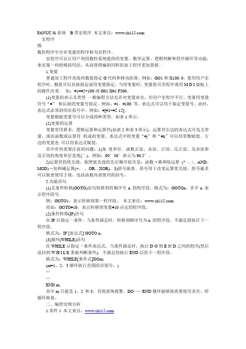
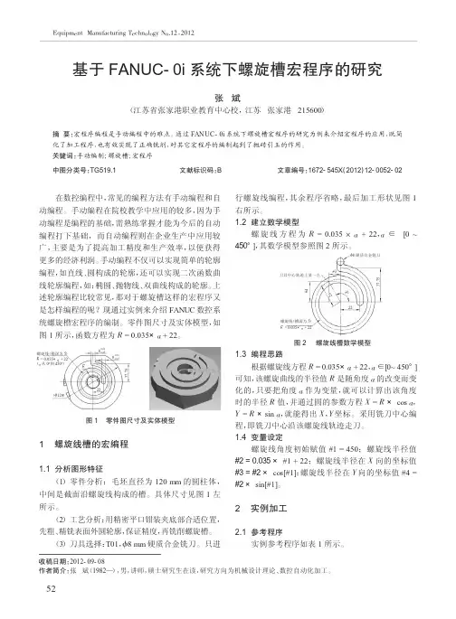
FANUC 0i系统B类宏程序本文来自:宏程序图数控程序中含有变量的程序称为宏程序。
宏程序可以让用户利用数控系统提供的变量、数学运算、逻辑判断和程序循环等功能,来实现一些特殊的用法,从而使得编制同样的加工程序更加简便。
1.变量普通加工程序直接用数值指定G代码和移动距离,例如,GO1和X100. 0。
使用用户宏程序时,数值可以直接指定或用变量指定。
当用变量时,变量值可用程序或用M D I面板上的操作改变。
如:#1=#2+100或G01 X#1 F300。
(1)变量的表示及类型一般编程方法允许对变量命名,但用户宏程序不行。
变量用变量符号“#”和后面的变量号指定。
例如:#1、#100 等。
表达式可以用于指定变量号。
此时,表达式必须封闭在括号中。
例如:#[#1+#2-12]。
变量根据变量号可以分成四种类型,如表1所示。
(2)变量的运算变量常用算术、逻辑运算和运算符(如表2和表3所示)。
运算符右边的表达式可包含常量,或由函数或运算符组成的变量。
表达式中的变量“#j”和“#k”可以用常数赋值。
左边的变量也可以用表达式赋值。
其中有些需要注意的问题:1)角度单位。
函数正弦、余弦、正切、反正弦、反余弦和反正切的角度单位是度(°)。
例如:90°30′表示为90.5°。
2)运算符的优先级。
按照优先级的先后顺序依次是:函数→乘和除运算(* 、/、AND、MOD)→加和减运算(+、-、OR、XOR)。
3)括号嵌套。
括号用于改变运算优先级。
括号最多可以嵌套使用5级,包括函数内部使用的括号。
2.功能语句(1)无条件转移(GOTO)语句转移到有顺序号n 的程序段。
格式为:GOTOn,其中n 表示程序段号。
例:GOTO1,表示转移到第一程序段。
本文来自:再如:GOTO#10,表示转移到变量#10决定的程序段。
(2)条件转移(IF)语句在IF后指定一条件,当条件满足时,转移到顺序号为n 的程序段,不满足则执行下一程序段。
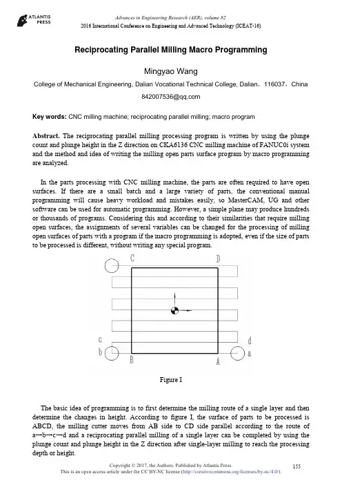
Reciprocating Parallel Milling Macro ProgrammingMingyao WangCollege of Mechanical Engineering, Dalian Vocational Technical College, Dalian ,116037,China****************Key words: CNC milling machine; reciprocating parallel milling; macro programAbstract. The reciprocating parallel milling processing program is written by using the plunge count and plunge height in the Z direction on CKA6136 CNC milling machine of FANUC0i system and the method and idea of writing the milling open parts surface program by macro programming are analyzed.In the parts processing with CNC milling machine, the parts are often required to have open surfaces. If there are a small batch and a large variety of parts, the conventional manual programming will cause heavy workload and mistakes easily, so MasterCAM, UG and other software can be used for automatic programming. However, a simple plane may produce hundreds or thousands of programs. Considering this and according to their similarities that require milling open surfaces, the assignments of several variables can be changed for the processing of milling open surfaces of parts with a program if the macro programming is adopted, even if the size of parts to be processed is different, without writing any special program.Figure IThe basic idea of programming is to first determine the milling route of a single layer and then determine the changes in height. According to figure I, the surface of parts to be processed is ABCD, the milling cutter moves from AB side to CD side parallel according to the route of a →b→c→d and a reciprocating parallel milling of a single layer can be completed by using the plunge count and plunge height in the Z direction after single-layer milling to reach the processing depth or height.2016 International Conference on Engineering and Advanced Technology (ICEAT-16)1. Write reciprocating parallel milling processing program by using the plunge count in the Z directionIt writes the reciprocating parallel milling processing program by using the plunge count in the Z direction. The origin of coordinates is the center of parts, the flat-bottomed end mill is adopted and the cutter diameter is Φ16.Writing of reciprocating parallel milling program parallel to X-axis:%O0001G54G91 G28 Z0G90 G00 Z100M03 S800#1=100 (Length of rectangle in the X direction: 100mm)#2=100 (Length of rectangle in the Y direction: 100mm)#3=16 (Use the flat-bottomed end mill and the cutter diameter is Φ16)#4=-#2/2 (Determine the coordinate in the Y direction according to the assignment of start point and length of rectangle in the Y direction)#5=0.8 (Modify the gradient of independent variable according to the material and the step is 0.8 times)#7=#5*#3 (The step value is 0.8 times of the cutter diameter)#8=[#1+#3]/2+15 (Determine the coordinate of milling start point of rectangle in the X direction, 15 is the safe distance of displacement)#9=0 (Processing count in the Z direction, the initial assignment is 0)#10=10 (Total removal rate in the Z direction)#11=4 (Working allowance in the Z direction is removed by 4 times)#12=#10/#11 (Determine the cutting depth according to the total amount and count)#13=0 (Coordinate of parts in the Z direction)N1000 G00 X#8 Y#4 F200#9=#9+1 (Determine the start point of X-axis of reciprocating milling, the cycle count in the Z direction plus 1 for each time)#13=#13+#12 (Determine the coordinate of circulatory cutting in the Z direction)G01 Z-#13 (Straightly feed to the cutting depth)#14=#4 (Determine the start point coordinate of Y-axis of reciprocating milling)N2000 G01 X-#8 (Process from the right side to the left side of workpiece parallel )#14=#14+#7 (Determine the step value)Y#14 (Process on the left side of parts parallel to Y-axis)X#8 (Process from the left side to the right side of workpiece parallel )#14=#14+#7 (Determine the step value)Y#14 (Process on the right side of parts parallel to Y-axis)I F [#14 L T[#2/2+0.2*#3]] GOTO2000 (Conditional transfer statement, conditional judgment of processing location at Y-axisG0 Z30 (Lift the cutter to the safe location after parallel milling)I F [#9 L T#11] GOTO1000 (Conditional transfer statement, conditional judgment of count in the Z direction)G0 Z200M05M30%2. Write reciprocating parallel milling processing program by using the plunge height in the Z directionIt writes the reciprocating parallel milling processing program by using the plunge height in the Z direction. The origin of coordinates is the center of parts, the flat-bottomed end mill is adopted and the cutter diameter is Φ16.%O0002G54G91 G28 Z0G90 G00 Z100M03 S800#1=100(Length of rectangle in the X direction: 100mm)#2=100 (Length of rectangle in the Y direction: 100mm)#3=16 (Use the flat-bottomed end mill and the cutter diameter is Φ16)#4=-#2/2 (Determine the coordinate in the Y direction according to the assignment of start point and length of rectangle in the Y direction)#5=0.8 (Modify the gradient of independent variable according to the material and the step is 0.8 times)#7=#5*#3 (The step value is 0.8 times of the cutter diameter)#8=[#1+#3]/2+15 (Determine the coordinate of milling start point of rectangle in the X direction, 15 is the safe distance of displacement)#9=0 (Coordinate assignment in the Z direction, the initial value is 0)#10=30 (Total removal rate in the Z direction)#11=5 (Removal height in the Z direction)N3000 G00 X#8 Y#4 F200 (Determine the start point of X-axis of reciprocating milling)#9=#9+#11 (Processing height assignment in the Z direction)Z-#9F200 (Height from plunge to assignment in the Z direction)#14=#4 (Determine the start point of Y-axis of reciprocating milling)N2000 G01 X-#8 (Process from the right side to the left side of workpiece parallel )#14=#14+#7 (Determine the step value)Y#14 (Process on the left side of parts parallel to Y-axis)X#8 (Process from the left side to the right side of workpiece parallel )#14=#14+#7 (Determine the step value)Y#14 (Process on the right side of parts parallel to Y-axis)I F [#14 L T[#2/2+0.2*#3]] GOTO3000 (Conditional transfer statement, conditional judgment of processing location at Y-axisG0 Z30 (Lift the cutter to the safe location after parallel milling)I F [#9 L T#10] GOTO4000 (Conditional transfer statement, judgment of processing height in the Z direction)G0 Z200M05M30%3. ConclusionThe programming should first determine the independent variable and then determine the plunge direction whether it is parallel to X-axis or Y-axis according to the milling direction of parts and finally conduct conditional judgment of end point by using the conditional transfer statement. During parallel reciprocating milling, the step determines the processing speed. If the step is small, there will be more operations of CNC system and plunge counts, thus the processing efficiency is low and the precision is high; if the step is large, there will be less operations of CNC system and plunge counts, thus the processing efficiency is high and the precision is low. Therefore, the step must be chosen reasonably according to the processing requirements. Generally, a larger step is chosen on the premise of meeting the processing requirements. The single-layer processing is completed by using the plunge count or plunge height in the Z direction. In addition, attention should be paid to the location of the origin of coordinate of program during programming and tool setting.References[1]Peter Smid, CNC Programming Handbook. Beijing: Chemical industry Press, 2005.[2]Shen Jianfeng, Yujun. Numerical Control Lathe Worker( advanced). Beijing: Engineering Industry Press, 2006.[3]Zhou Baoniu. CNC Programming and Machining Technology. Beijing: Engineering Industry Press, 2009.。

第五章FANUC 0I 系统数控铣床宏编程实例5.1特殊曲线轮廓零件的编程零件的轮廓加工,既包括简单几何轮廓零件的加工,又包括特殊曲线几何轮廓零件的加工。
对于由直线和圆弧组成的简单几何轮廓零件的加工,编程人员可直接用零件图上给定的已知条件,或经过简单的数学计算,可获得基点坐标值,直接编写出零件的加工程序。
对于特殊曲线轮廓零件的编程,采用一般的编程方法,通常编程人员计算量较大,有时并不能得到某些基点的精确坐标,这是在编程过程中的难点所在,对于这一类特殊曲线轮廓零件的加工,这里仅介绍轮廓曲线的方程式为已知时,可采用宏程序编程的方法,既大大减小了计算量,又具有一定的通用性,在工程中具有一定的适应性。
5.1.1 椭圆形零件的轮廓编程(1)零件图分析如图5-1所示,编制一个宏程序加工椭圆的外轮廓。
毛坯尺寸φ110×40mm.材料为45钢。
已知椭圆的长半轴为50mm,椭圆短半轴为40mm,加工椭圆轮廓的高度为20mm.图5-1(2)工艺分析1)程序原点及工艺路线采用三爪自定心夹盘装夹,工件坐标系原点设定在工件上表面中心处。
2)变量设定#1=(A) *椭圆长半轴长#2=(B) *椭圆短半轴长#3=(C) *椭圆轮廓的高度#4=(I) *四分之一圆弧切入的半径#7=(D) *平底立铣刀半径#9=(F) *进给速度#11=(H) *Z方向自变量赋初值#17=(Q) *自变量每层递增量3)刀具选择φ20平底立铣刀(3)参考程序主程序:O0511;G28 G91 Z0.;G17 G40 G49 G80;S1200 M03;G54 G90 G00 X0. Y0.;G43 H01 Z30.;G65 P1511 A50. B40. C20. I20.D10. H0. Q2. F300.;M05;M03;子程序:O1511;G00 X0. Y-[#2+#4]; *定位到起刀点上方WHILE[#11GT-#3] DO1; *当#11>-#3时,循环1继续#11=#11-#17; *铣刀Z方向的坐标值Z#11; *Z向快速进刀到#11处G01G41 X#4 D01 F#9; *加入刀具半径左补偿G03 X0. Y-#2 R#4 F#9; *圆弧切入到椭圆起点#12=-90.; *椭圆角度自变量赋初值WHILE[#12GT-450.] DO2; *当#12>-450.时,循环2继续#12=#12-0.5; *角度#12减0.5度#21=#1*COS[#12]; *角度#12时的椭圆X方向坐标值#22=#2*SIN[#12]; *角度#12时的椭圆X方向坐标值G01 X#21 Y#22; *椭圆加工END2; *循环2结束G03 X-#4 Y-[#2+#4] R#4; *圆弧切出G00 G40 X0.; *取消刀具半径补偿END1; *循环1结束G00 Z30.; *刀具返回初始平面M99; *程序结束返回(4)本题回顾:5.1.2角度线段的轮廓编程(1)零件图分析;如图5-2所示,编制一个宏程序加工角度线段的形外轮廓。