汇川—InoTouch系列触摸屏人机界面用户手册
- 格式:pdf
- 大小:2.56 MB
- 文档页数:36
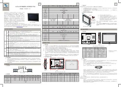
目 录第一章 关于InoTouch Editor编程软件的安装......................- 6 -1.1 InoTouch系列HMI和InoTouch Editor软件的简介..................................- 6 -1.2 安装InoTouch Editor编程软件................................................................- 10 -1.3 系统连接图..............................................................................................- 12 -1.4 InoTouch系列人机界面的系统设定........................................................- 13 - 第二章 制作一个简单的工程.....................................- 21 - 第三章 程序的编译、仿真与下载.................................- 27 -3.1 编译.........................................................................................................- 27 -3.2仿真..........................................................................................................- 28 -3.3下载程序...................................................................................................- 29 - 第四章 InoTouch Editor软件的使用.............................- 34 -4.1文件..........................................................................................................- 34 -4.2编辑..........................................................................................................- 35 -4.3绘图..........................................................................................................- 44 - 第五章 系统参数...............................................- 53 -5.1 HMI设置................................................................................................- 53 -5.2 用户密码..................................................................................................- 54 -5.3 提示信息..................................................................................................- 55 -5.4 系统设置..................................................................................................- 56 - 第六章 窗口...................................................- 58 -6.1 窗口类型..................................................................................................- 58 -6.2 窗口的建立、设定与删除.........................................................................- 59 -6.3 基本窗口的使用.......................................................................................- 61 - 第七章 图形库、声音库的建立与使用.............................- 71 -7.1用户图库的建立........................................................................................- 71 -7.2 声音库......................................................................................................- 81 - 第八章 文字标签库与多国语言显示...............................- 85 -8.1文字标签库的相关操作说明......................................................................- 85 -8.2 文字标签库的使用....................................................................................- 87 -8.3 多国语言的显示.......................................................................................- 89 - 第九章 地址标签库的建立与使用.................................- 92 -9.1地址标签库的建立.....................................................................................- 92 -9.2 地址标签库的使用....................................................................................- 93 - 第十章 控件的一般属性.........................................- 96 -10.1 选择PLC...............................................................................................- 96 -10.2 读写地址设定.........................................................................................- 96 -10.3数据格式选择..........................................................................................- 98 -10.4 图库的使用............................................................................................- 98 -10.5标签属性的设定.....................................................................................- 101 -10.6轮廓属性................................................................................................- 103 - 第十一章 控件的安全防护......................................- 105 -11.1 用户密码与可操作控件类别设定............................................................- 105 -11.2控件“安全属性”.......................................................................................- 106 - 第十二章 索引寄存器..........................................- 116 - 第十三章 控件................................................- 121 -13.1 位状态指示灯控件 (bit lamp)................................................................- 121 -13.2 位状态设置控件 (set bit).......................................................................- 123 -13.3 位状态切换开关控件 (toggle switch)....................................................- 125 -13.4 多状态指示灯控件 (word lamp)............................................................- 126 -13.5 多状态设置控件 (set word)...................................................................- 129 -13.6 多状态切换开关控件 (multi-state switch)..............................................- 134 -13.7 数值输入与数值显示控件(numeric input and numeric display)............- 137 -13.8 字符输入与字符显示控件(ASCII input and ASCII display)...................- 143 -13.9 项目选单(Option List)............................................................................- 145 -13.10 滑动开关控件 (slide object)................................................................- 148 -13.11 功能键控件 (function key)...................................................................- 150 -13.12 移动图形控件 (moving shape)...........................................................- 152 -13.13 动画控件 (animation).........................................................................- 156 -13.14 表针控件 (meter display)....................................................................- 160 -13.15 棒图控件 (bar graph)..........................................................................- 165 -13.16 XY 曲线 (XY Plot)............................................................................- 170 -13.17 数据群组显示(data block)...................................................................- 178 -13.18 备份控件 (backup).............................................................................- 186 -13.19 PLC控制控件(PLC Control)..............................................................- 188 -13.20 排程 (Schedule).................................................................................- 192 - 第十四章 资料取样、趋势图与历史数据显示......................- 207 -14.1资料取样................................................................................................- 207 -14.2 趋势图...................................................................................................- 209 -14.3历史数据显示.........................................................................................- 216 - 第十五章 事件登录、事件显示与报警显示、报警条................- 221 -15.1 事件登录管理........................................................................................- 221 -15.2 事件显示...............................................................................................- 225 -15.3 报警显示与报警条.................................................................................- 231 -第十六章 数据和配方资料传送..................................- 236 -16.1建立定时式资料传输.............................................................................- 236 -16.2使用触发式资料传输/建立配方资料传输................................................- 237 -16.3 InoTouch Editor人机界面上配方资料更新与保存.................................- 241 - 第十七章 键盘的设计与使用....................................- 244 -17.1 调用自制的键盘...................................................................................- 244 -17.2 使用直接窗口的方式来调用键盘..........................................................- 246 -17.3 将键盘固定在需要输入的画面上..........................................................- 249 -17.4 制作汉字键盘输入汉字.........................................................................- 250 - 第十八章 系统保留寄存器地址和作用............................- 253 -18.1 一般状态与控制...................................................................................- 253 -18.2 数值输入状态.......................................................................................- 254 -18.3 配方资料..............................................................................................- 255 -18.4 工作按钮与快选窗口............................................................................- 255 -18.5 事件纪录..............................................................................................- 256 -18.6 资料取样纪录.......................................................................................- 256 -18.7 密码与操作等级...................................................................................- 257 -18.8 HMI时间............................................................................................- 258 -18.9 HMI硬件............................................................................................- 259 -18.10 与远程HMI的联机状态.....................................................................- 259 -18.11 与PLC的联机状态............................................................................- 259 -18.12 与本机连接的远程的机器...................................................................- 261 -18.13 MODBUS Server站号.....................................................................- 261 -18.14 COM通讯参数更改..........................................................................- 261 -18.15 文件管理............................................................................................- 263 -18.16 PLC & 远程 HMI的IP address设定...............................................- 263 -18.17 远程打印服务器设定..........................................................................- 263 -18.18 地址索引功能.....................................................................................- 264 -18.19 本机 HMI 内存地址范围....................................................................- 264 - 第十九章 以太网络通讯与多台InoTouch系列HMI互联.............- 267 -19.1 HMI与HMI间的通讯.........................................................................- 267 -19.2 计算机与HMI间的通讯.......................................................................- 269 -19.3 控制连接在其它HMI上的PLC............................................................- 270 - 第二十章 如何将InoTouch系列HMI设定成MODBUS从站............- 274 -20.1 增加设定一个MODBUS Server设备...................................................- 274 -20.2 如何读写一个MODBUS Server设备...................................................- 275 -20.3如何在线更改MODBUS Server的站号................................................- 276 -20.4关于MODBUS各地址的说明................................................................- 277 - 第二十一章 宏指令说明........................................- 279 -21.1 怎样建立和执行宏指令..........................................................................- 279 -21.2 函数功能...............................................................................................- 283 -21.3 宏指令的语法........................................................................................- 299 -21.4 宏指令举例...........................................................................................- 306 -21.5 应用中的实例........................................................................................- 311 - 第二十二章 穿透通讯功能......................................- 316 -22.1 穿透工具软件介绍.................................................................................- 316 -22.2 功能使用说明........................................................................................- 317 -22.3 穿透举例说明........................................................................................- 319 -关于InoTouch Editor编程软件的安装关于InoTouch Editor编程软件的安装第一章 关于InoTouch Editor编程软件的安装1.1 InoTouch系列HMI和InoTouch Editor软件的简介1.1.1 InoTouch系列HMI的简介InoTouch系列HMI可以分为标准配置产品、网络型产品配备以太网口;有的还配备音频输出;IT5104/IT5121除了配备以太网口、音频输出外,还可选择配置视频输入等。


InoTouch系列人机界面用户手册前言- 1 -前言感谢您购买汇川控制技术有限公司自主研发、生产的InoTouch系列触摸屏人机界面HMI以下简称HMI在使用我公司InoTouch系列HMI产品前敬请您仔细阅读本手册以便更清楚地掌握产品的特性更安全地使用本产品。
本手册主要描述InoTouch系列HMI的规格、特性及使用方法等。
而关于本产品的用户程序开发环境的使用及用户程序设计方法请参考本公司另外发行的《InoTouchEditor编程软件手册》。
安全注意事项在开始操作之前请仔细阅读操作指示、注意事项以减少意外的发生。
产品及产品手册中的“危险、警告、注意”事项并不代表所应遵守的所有安全事项只作为各种操作安全注意事项的补充。
因此负责产品安装、操作的人员必须经严格培训遵守相关行业的安全规范严格遵守本手册提供的相关设备注意事项和特殊安全指示按正确的操作方法进行设备的各项操作。
本手册中将安全注意事项分为“危险”与“注意”两个等级。
危险错误操作可能造成人员死亡、严重的身体伤害或重大损失。
注意错误操作可能导致人员的伤害或财产损失。
这些全记述在重要内容里请严格遵守。
产品附带的使用说明书要妥善保管以便需要时取出阅读并必须交给最终用户。
设计注意事项危险应用时请务必设计安全电路保证使用时的安全设计中应考虑的方面包括前言 InoTouch系列人机界面用户手册- 2 -发生主电源故障或HMI故障时HMI控制系统的设计应能确保用户系统的整体安全否则错误的输出信号或 ??HMI故障可能造成事故。
用于中断或限制正常设备移动的互锁和其他电路如紧急停止、常规保护、正反转以及那些用于防止设1备损坏的装置如上、下和往复移动限位都应设置在HMI以外。
当HMI不能检测的输入 /输出控制区发生错误时这些区域中可能会出现意外移动。
因此为了防止不安2全的机械移动应设置 “故障保护电路”并且该电路应完全在HMI之外。
如果外部模块的继电器或晶体管发生故障使输出线圈保持 “ON”或“OFF”则可能发生严重事3故。

汇川技术HMI触摸屏应用笔记使用说明HMI应用笔记说明:该文档是基于当前产品的使用和注意事项,随着产品功能的不断更新,如果现场有遇到新的问题或得到新的经验,也请反馈给项目组。
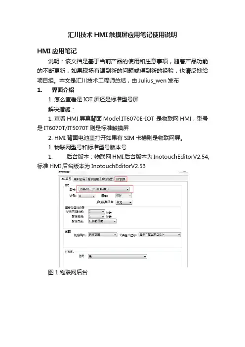
本文是汇川技术工程师总结,由Julius_wen发布1.界面介绍1.怎么查看是IOT屏还是标准型号屏解决措施:1.查看HMI屏幕背面Model:IT6070E-IOT 是物联网HMI,型号是IT6070T/IT5070T则是标准触摸屏2.HMI背面电池盖打开如果有SIM卡槽则是物联网屏。
1.物联网型号和标准型号版本号1.后台版本:物联网HMI后台版本为InotouchEditorV2.54,标准HMI后台版本为InotouchEditorV2.53图1物联网后台图2 标准后台2、内核版本:物联网HMI内核最新版本为10204-01(可在HMI 屏幕背面Ver:查看)二、上下载类1、USB线下载时提示连接失败可能原因:1、USB驱动未安装成功;2、USB驱动被占用;3、现场干扰解决措施:1、拔插USB线,或者查看设备管理识别的USB设备,显示如下图:表示驱动未安装,请手动安装设备驱动,具体步骤如下:B驱动在HMI编程软件安装目录里面,举例如果编程软件安装在F盘,则路径为F:\Inovance Control\InoTouch\driver\usb2.2)通过Windows设备管理器,更新驱动,从安装目录中安装驱动,USB连接成功后,windows设备管理器显示如下图。
2、拔插USB线,或者查看设备管理器识别的USB设备,正常显示如下图:假设识别了其他的设备,例如下图:则点击驱动邮件更新驱动程序,如下图:然后选择”浏览计算机查找驱动程序”,如下图:然后点击”从计算机设备驱动程序列表中选择”,如下图最后选择”Inovance Control IToch Serials”驱动,点击下一步安装就可。
3、现场干扰,查看设备管理器,设备驱动在不断识别,不断闪烁。
InoTouch系列人机界面用户手册前言- 1 -前言感谢您购买汇川控制技术有限公司自主研发、生产的InoTouch系列触摸屏人机界面HMI以下简称HMI在使用我公司InoTouch系列HMI产品前敬请您仔细阅读本手册以便更清楚地掌握产品的特性更安全地使用本产品。
本手册主要描述InoTouch系列HMI的规格、特性及使用方法等。
而关于本产品的用户程序开发环境的使用及用户程序设计方法请参考本公司另外发行的《InoTouchEditor编程软件手册》。
安全注意事项在开始操作之前请仔细阅读操作指示、注意事项以减少意外的发生。
产品及产品手册中的“危险、警告、注意”事项并不代表所应遵守的所有安全事项只作为各种操作安全注意事项的补充。
因此负责产品安装、操作的人员必须经严格培训遵守相关行业的安全规范严格遵守本手册提供的相关设备注意事项和特殊安全指示按正确的操作方法进行设备的各项操作。
本手册中将安全注意事项分为“危险”与“注意”两个等级。
危险错误操作可能造成人员死亡、严重的身体伤害或重大损失。
注意错误操作可能导致人员的伤害或财产损失。
这些全记述在重要内容里请严格遵守。
产品附带的使用说明书要妥善保管以便需要时取出阅读并必须交给最终用户。
设计注意事项危险应用时请务必设计安全电路保证使用时的安全设计中应考虑的方面包括前言 InoTouch系列人机界面用户手册- 2 -发生主电源故障或HMI故障时HMI控制系统的设计应能确保用户系统的整体安全否则错误的输出信号或 ??HMI故障可能造成事故。
用于中断或限制正常设备移动的互锁和其他电路如紧急停止、常规保护、正反转以及那些用于防止设1备损坏的装置如上、下和往复移动限位都应设置在HMI以外。
当HMI不能检测的输入 /输出控制区发生错误时这些区域中可能会出现意外移动。
因此为了防止不安2全的机械移动应设置 “故障保护电路”并且该电路应完全在HMI之外。
如果外部模块的继电器或晶体管发生故障使输出线圈保持 “ON”或“OFF”则可能发生严重事3故。

Touchpad controllerUser Manual – installation – operationContentsGeneral drawings2 Fixing control panel to wall21. General installation instructions32. Connecting modular cables33. Connecting additional control components43.1 Introduction43.2 Control function ‘switch on/off’43.3 Control function ‘change fan speed’44. Initialising system (prepare for use)55. Operation55.1 Functions of keys55.2 Operation56. Troubleshooting6Fixing control panel to wall 1234General drawings1. General installation instructions— Read this page carefully before starting the installation.— All installation work must be carried out by expert personnel.— Ensure that the appliances are disconnected from the mains before they are opened.— Avoid unnecessary contact with electronic components.Introduction:1. This manual is intended for all Biddle appliances with a built-in electronic interface.2. This manual describes the installation and use of the Biddle electronic control system.3. Several functions in this manual are only available from a certain version of a control system component. These functions are marked. Whenever you change an existing system you should compare the version number on the component with the version number in the manual.Installation details:1. Up to 10 appliances may be connected to one control panel.2. The total length of all modular cables in one system must be less than 100 metres.3. When installing the modular cable care should be taken to avoid interference with the cable by (electro)-magnetic fields as far as possible (therefore do not lay the cable close to high-voltage cables, fluorescent light starters, etc.)Components:The control system comprises the following components:1. Control panel consisting of 3, 4, 5 or 6 keys.2. Built-in interface with 3 or 6 output contacts, depending on the type of appliance.3. Modular cable including modular plugs, for connecting the control panel to one or more appliances. N.B.: B.T. type telecommunication cables are not suitable! The cable can be ordered from Biddle and is available in various lengths.Installation procedure:1. Connect modular cables + install control panel.2. Connect any customised controls, with control components with potential-free contacts.3. Provide all appliances with a power supply.4. Initialise the system.2. Connecting modular cablesA. Appliances with external connectionsType of appliance:— Modular fan coil unit (PS-B)— Air curtain (KW/MW/GW/KE/ME/GE/CAT/CAT-V)— Cassette air heater (KLV/KLV-E/KLVV)B.Appliances with internal connections Type of appliance:— Fan coil unit (B)— Extractor fan cabinetN.B.: The modular cables (X70) can be connected to both connectors (XiS)(see fold-out sheet, page 2).3. Connecting additional control componentsIf you have no control components to install, you can skip this section and go on to section 4 ‘Initialise the system’.3.1 IntroductionAs well as the basic system functions, there is also a possibility of connecting control components (e.g. room thermostat, timer BMS-controlled relay or door switch) to an appliance. Combinations of control components can also be used.N.B.: For remote switching on blocks X62/X72 volt free contacts are required. These contacts are advised to be gold plated and to have a low relay less than 20 m W to handle 1 mA at 5Vdc.Possible control functions:Control function Control range Adaptation to interface ofconnected appliance Connection points onblock X62/X72Connectionsummaryswitch on/off one appliance (local)none terminals T and G see § 3.2 switch on/off all appliances in system (general)remove jumper 6terminals T and G see § 3.2 change fan speed one appliance (local)none terminals D, P and G see § 3.3 change fan speed all appliances in system (general)remove jumper 5terminals D, P and G see § 3.3 N.B.: The function ‘switch on/off’ does not apply to the KLVV-unit. Consult the user manual of the unit when you want to connect control components to terminals T and G.3.2 Control function ‘switch on/off’1. Remove T-G bridge (X62/X72. see fold-out sheet, page 2) only from the appliance towhich the control component is to be connected.2. Connect the control component between T and G.— Contact made between T and G: Applicance stand-by.— No contact between T and G: Appliance/system off.3. General switching If the control function is to apply to the whole system, remove jumper 6(X64). This should only be done in the appliance to which the control component isconnected. Place the jumper on the reserve positions intended for it (X65), so that it can beused again later.3.3 Control function ‘change fan speed’1. Connect the control component between D and/or P and G (X62/X72, see fold-out sheet, page2). Important: do not disconnect T-G bridge.— Contact made between D and G : Appliance/system runs 1 speed higher than the controlpanel indicates (both speed and electric heating).— No contact between D and G Appliance/system working as indicated on the control panel.— Contact made between P and G Appliance/system runs at fan speed three (electric heatingstage remains unchanged, either one or two).— No contact between P and G Appliance/system working as indicated on the control panel.— Contact made between D, P and G: Appliance/system runs at fan speed three and electricheating stage two.N.B.: The functions using terminals P and G only are available from interface version V4.0Rev.06. Code IC 10 in the illustration on page 2 shows where you can find the version number.2. General switching: If the control function is to apply to the whole system, remove jumper 5(X64) as indicated in the facing illustration. This should only be applied to the appliance towhich the control component is connected. Place the jumper on the reserve positions intendedfor it (X65), so that it can be used again later.NB: General switching’ of the contact between P and G requires control pad version V2. IRev.02 or higher and interface version V4.O Rev.07 or higher. You can find the versionnumber on the printed circuit board of the control pad. In an existing system the control padcould be of a previous version. If the contact between P and G should still apply to the wholesystem, you should order a new control pad from Biddle.3. If the electric heating is not to be stepped up at the same time, remove jumper 4 (X64) asindicated in the illustration. This should be done in each appliance for which the function is required. Place the jumper on the reserve positions intended for it (X65), so that it can be used again later.14564. Initialising the system (prepare for use)When to use:1. On first installation.2. On each extension of the system.3. When checking cables.To start the procedure:1. Press keys 1, 2 and 3 simultaneously.—After 10 seconds the LEDs on keys 1 and 2 will start to flash. This flashing will continue for two minutes.— The LED on key 3 will then flash the same number of times as there are appliances in the system. The system is now ready for use.5. Operation5.1 Functions of keysLED lights when speed setting is ‘low’.LED flashes during initialisation.— Set speed to ‘low’.— Switch off appliance.— Start initialisation.LED lights when speed setting is ‘medium’LED flashes during initialisation.— Set speed to ‘medium’.— Switch off appliance.— Start initialisation.LED lights when speed setting is ‘high’.LED indicates number of appliances connected when initialisation is complete.— Set speed to ‘high’.— Switch off appliance.— Start initialisation.LED lights when electric heating is set to ‘low’.— Set electric heating to ‘low’.— Switch off electric heating.— Set electric heating to ‘low’ and speed to ‘low’.LED lights when electric heating is set to ‘high’.— Set electric heating to ‘high’.— Switch off electric heating— Set electric heating to ‘high’ and speed to ‘medium’.LED-R lights when setting is ‘Recirculate’ or standby.LED-V lights when setting is ‘Ventilate’.— Set air intake valve to ‘Ventilate’.— Set air intake valve to ‘Recirculate’.5.2 OperationA.Turn on appliance : Press key 1, 2, 3, 4 or 5.B.Turn off appliance : Press speed key (1, 2 or 3) on which the LED is illuminated. LED-R (if present) remains illuminated.Safety functions electric heating:1.The following scenarios will automatically be corrected:— Speed off, electric heating on.— Speed low, electric heating high.2. Appliance operates differently from control panel:If the appliance has just been switched off, it may start running again spontaneously.This is in order to discharge the heat stored in the heating elements.6.TroubleshootingAppliance not working:Check point Possible cause Action1no voltage on appliance check power supply to appliance2system not yet initialised start initialisation; see section 4 ‘Initialising the system’3poor contact in modular plug;check contacts (ensure plastic packaging is completely removed)4no bridge between terminals T and G fit bridge between terminals T and G on block X62/72. (see section 3‘Connecting Customised Control components’)5fuse(s) in appliance defective replace fuse (only to be done by skilled personnel)Appliance not working as expected:Check point Fault Possible cause Action/explanation1appliance (with electric heating)starts working spontaneously continued running of electricallyheated appliancesBiddle safety function; see section 5‘Operation’control components are notproperly connectedcheck system; see section 3‘Connecting Customised ControlComponents’2appliance works differently fromexpectationthe jumpers(l-3 red) on the interface are no longer in accordance with factory setting check jumper position against Specifications for factory setting jumper block X643electric heating not working appliance has overheated check maximum thermostat(see appliance manual) Factory setting jumper block X64Appliance type Jumper 1Jumper 2Jumper 3Jumper 4-6 appliance with electric heating with 2 positions present open present present CAT-air curtain open present present present KLV-E open present open present KLVV open open open presentall other appliances present present present present。
INTOUCH组态操作中央监控系统操作手册一、上位机监控系统组成中央监控系统软件采用WONDERW ARE的HMI人机界面INTOUCH中文版8.0图控软件,采用DDE的方式与现场SIEMENS 公司的S7-400系列的PLC进行通讯。
INTOUCH中文版8.0图控软件是工控领域最成熟的组态软件,大量应用于自动化监控系统,在半导体厂中央监控领域的指定的图控产品。
上位机的操作系统采用WINDOWS2000的系统,增强系统的稳定性,主要的运行软件有:1、Intouch-View 是图控运行版软件,该软件是我们能看到的图形系统软件,是操作人员和控制系统之间的人机界面,所有的对控制系统的操作观测,参数操作修改,参数观测,历史记录均由此软件完成,VIEW软件在上位机开机后即自动运行,只有最高权限才能退出系统。
2、I/O Server 是DDE数据采集通讯软件,I/O Server是Intouch-View和现场PLC之间的桥梁,专门负责与PLC之间通讯,把PLC的数据采集上来至上位机,然后通过DDE的方式把数据传递给Intouch-View显示和处理。
该软件在上位机开机后即自动运行;3、Alarm DB Logger Manager 软件是专门的报警处理软件,用于处理Intouch-View软件中所有报警记录,和对报警以及事件的处理,比如:报警存档,报警分类等。
该软件在上位机开机后即自动运行;4、STEP-7软件,该软件是针对SIEMENS S7-400PLC编程软件,所有控制程序均在此软件完成,并下载到PLC里运行,本控制系统中未购买此软件,故上位机中只要DEMO版。
强烈建议用户不要自行用此软件去修改程序,由此可能会导致不可预见的故障。
5、Intouch-Make 是图控开发版软件,用于开发、制作Intouch-View所能看到的所有图形,配置用户,配置数据库等,本控制系统中未购买此软件,故上位机中只有DEMO版,且不能打开本系统的数据库。