人机界面-造型手册960822
- 格式:pdf
- 大小:3.46 MB
- 文档页数:12
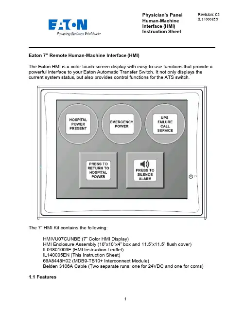
Physician’s Panel Human-Machine Interface (HMI) Instruction Sheet Revision: 02 IL140005ENEaton 7” Remote Human-Machine Interface (HMI)The Eaton HMI is a color touch-screen display with easy-to-use functions that provide a powerful interface to your Eaton Automatic Transfer Switch. It not only displays thecurrent system status, but also provides control functions for the ATS switch.The 7” HMI Kit contains the following:HMIVU07CUNBE (7” Color HMI Display)HMI Enclosure Assembly (10”x10”x4” box and 11.5”x11.5” flush cover)IL04801003E (HMI Instruction Leaflet)IL140005EN (This Instruction Sheet)66A8448H02 (MDB9-TB10+ Interconnect Module)Belden 3106A Cable (Two separate runs: one for 24VDC and one for coms)1.1 FeaturesThere are two types of features incorporated into the HMI: Status and Control. Below are lists of each:StatusHospital Power PresentEmergency PowerUPS Failure – Call ServiceWaiting to Retransfer to Hospital PowerAlarm Muted/Un-mutedControlManual Retransfer to Hospital Power buttonAlarm Silence button1.2 Set-up and WiringTo connect your HMI assembly to your Automatic Transfer Switch, simply follow the wiring diagram S002 (Sheet 3 of 5) or use this quick-reference guide.Each of the supplied Belden 3106A cables (two lengths of 30m) has three insulated wires and one ground connected to the shield of the cable. One cable is for 24VDC power; the other cable is for communications. Stickers are attached to each cable for identification.The UPS Alarm Contact wire max length/size is 92000 ft. (22AWG) to 370000 ft. (16AWG)All wire connections inside the HMI enclosure come pre-assembled from the factory. However, if the wire ever needs to be replaced or serviced, please refe rence the following information:Inside the HMI enclosure, the communication connector (Figure 1) connects to the HMI’s COM2 port (see item “B” on Figure 2). The module has screw-type terminal blocks to terminate the communication cable wiring. After the wires are installed, simply plug the adapter into COM2, and screw in both sides of the connector to the device. A picture of the adapter (Figure 1) is shown below. 24VDC power is done the same way. Wires are terminated in a green screw-type terminal block that plugs directly into the HMI. Termination points noted on drawing S002 (Sheet 3 of 5).Figure 1 - Serial Termination ModuleFigure 2 - HMI Rear-ViewThe communication setpoints on the ATC-300+ should be set from the factory as follows:Baud Rate: 9600Address: 01Terminated: Off (termination micro-switch on back side of ATC-300+)There is a hidden system menu in the HMI that allows the operator to change items like touch screen force, touch screen calibration, time & date, brightness & contrast, alarm and touch volume, and others. The HMI should be set up so the user will not have to adjust anything in the field. If a change is desired, open the HMI enclosure and press the small SYSTEM button (item “H” in Figure 2) on the back of the unit for threeseconds. This will take you to the system menu. The menus are self-explanatory, but if help is required, see instruction leaflet IL04802001E located in the plastic document pouch inside your ATS enclosure. After the adjustments have been made, simply push “Home”, followed by “Run”.1.3 Functional DescriptionThe HMI is programmed with one main screen which shows both status and control of the ATS unit. It also includes an audible alarm.Figure 3 - Main Screen (Indicators ON) Indicator #1Hospital Power Present – Green (ON), Gray (OFF)#4#5This indicator turns green when the main hospital power is present and available. It does not indicate that the ATS is connected to hospital power or not.Indicator #2Emergency Power – Red (ON), Gray (OFF)This indicator turns red when the ATS is connected to UPS backup power.Indicator #3UPS Failure Call Service – Flashing Yellow (ON), Gray (OFF)This indicator starts flashing yellow when the dry contact in the UPS system closes, indicating that there is a system failure at the UPS.Indicating Button #4Press To Return To Hospital Power – Flashing Blue (ON), Gray (OFF)This is a dual purpose indicator/button. The button will start flashing blue when the ATS unit is waiting to manually retransfer back to hospital power. To retransfer, simply press the button on the HMI screen, and the ATS unit will connect to hospital power. Pressing the button while it is gray will have no effect. Note: the transfer switch will automatically transfer back to Hospital Power if Emergency Power becomes unavailable while connected to Emergency Power. This is an automatic failsafe feature.Indicating Button #5Press to Silence/Un-Mute Alarm – Orange (ON), Gray (OFF)This button is used to silence the alarm tone when it is active. Pressing it will change the button color from gray to orange; the speaker icon will change to a muted symbol as well. To un-silence the alarm, press the button again. The alarm will continue to sound, and the button will change back to gray.AlarmsWaiting to Retransfer – Audible (Continuous Tone).The HMI will produce and audible alarm tone whenever the system is waiting for a user input to return to hospital power (Return to Hospital Power button is flashing blue). It will automatically go away as soon as the system transfers back to hospital powe r, or if the system is no longer waiting to return to hospital power. To manually silence the alarm tone, simply press the alarm silence button (Indicating Button #5).CAUTIONThis is a remote control device. Caution should be observed to make sure that appropriate procedures are in place when using manual retransfer. Appropriate procedures include, but are not limited to, switch doors being closed and latched, personnel knowledgeable of transfers, and other site safety recommended procedures.。

高性能HMI手册设计、实施和维护用于工厂操作有效HMIs的综合指南作者:比尔·霍利菲尔德达娜·奥利弗兰·尼莫埃迪·哈比比翻译:唐诗宋瓷目录第一部分:工业HMI的历史和现状我们从工业人机界面的起源和演变开始,介绍了集散控制系统(DCS)的引入所带来的积极和消极的问题,描述了工业HMIs的现状,并给出了显著改进的明确理由。
第二部分:HMI设计基础和最佳实践详细分析了HMI设计的概念和实践,对好的和坏的做法作了说明,提供了对现有系统的评估方法,介绍了提供适当的工艺概述、图形层次结构和逐步曝光细节的方法,以及详细的设计原则和实例,详细介绍了适当的物理控制台布局和其他因素。
第三部分:高性能HMI的设计与实现为高性能人机界面的开发、实现和维护提供了一种直观的方法,该方法对于新的应用或改进现有的HMI都是有用的。
第四部分:控制室、异常情况管理与HMI的未来详细分析了控制室环境对操作人员效能的影响,适当和不适当的做法和设计考虑包括在内,阐述了适当的异常状态管理和人的绩效的原则,展望了工业人机界面的未来发展方向和能力。
第一部分:工业HMI的历史和现状我们从工业HMI的起源和演变开始。
介绍了分布式控制系统(DCS)的引入所带来的积极和消极的问题。
工业HMIs的现状特征在于,有明显的改进理由。
第1章引言第2章工业HMI状态和操作员界面第3章改变HMI的理由第4章HMI最佳实践——管理概述第4章HMI最佳实践——管理概述。
“人类几乎是独一无二的,他们有能力从别人的经历中吸取教训,他们显然不愿意这样做,这也是值得注意的。
”——道格拉斯·亚当斯(1952-2001年) 高性能的人机界面使操作人员能够安全有效地监控和管理加工厂。
它的基础是显示符合已知人类因素问题的信息的最佳做法和异常情况管理的适当原则。
人机界面是操作人员了解流程的窗口,是操作效率的关键要素。
为了使高性能的人机界面成为可能,存在一些具体的实践。

兰州生物制品研究所空调控制系统—动物房人机界面及自控操作用户手册四川英德建设有限公司2006年12月目录1 系统运行 (1)2 系统登陆 (1)3 系统说明 (2)4 系统控制参数设置 (3)4.1标定参数设置 (3)4.2控制参数设置 (5)4.2.1 电加热控制参数 (6)4.2.2工况切换控制参数 (7)4.2.3一级加热阀控制参数 (7)4.2.4除湿控制参数 (7)4.2.5 系统报警参数设置 (7)4.2.6 PID控制参数设置 (7)4.3参数的输入方法 (8)5 系统运行状态显示 (8)5.1系统各控制电气的运行状态显示 (8)5.2系统运行状态显示 (10)5.3系统各控制值的实时显示 (10)5.4系统报警显示 (11)5.4.1报警过程 (11)5.4.2报警类别 (11)5.4.3报警显示 (12)5.4.4报警的确认 (13)6 系统控制操作 (14)6.1手动单控操作 (14)6.2自动控制操作 (17)6.2.1 工况自动切换控制 (18)6.2.2 电加热控制 (19)6.2.3 一级加热控制 (19)6.2.4 二级加热控制 (19)6.2.5 制冷控制 (20)6.2.6 加湿控制 (20)6.2.7 除湿控制 (20)6.2.8 送风控制、排风控制 (20)6.2.9 季节切换选择 (21)6.2.10 送风区域、排风系统选择 (21)6.2.11 空调系统的启动、停止 (22)7 系统功能 (22)7.1系统用户设置 (23)7.2时间设定 (25)7.3声音、对比度、清屏设定 (26)7.4系统退出 (26)1 系统运行HMI设备在接通电源后,设备自带的Windows CE系统便开始启动,启动完成后进入系统控制程序。
系统控制程序启动后首先会检测整个系统的运行环境,如果运行环境不在设定的范围内控制系统便会报警。
关于系统报警在后面会有详细地说明。
2 系统登陆系统启动后进入控制程序“登陆界面”如图1:图1 登陆界面点击按键触摸屏会弹出一个登陆对话框和软键盘如图2、图3:图2 登陆对话框图3 软键盘软键盘的用法和普通电脑的键盘用法基本相同,这里不再多加叙述。


摘要自动化立体仓库系统是在不直接进行人工处理的情况下自动地存储或取出物料的系统。
它功能强大、存取效率高、准确率高,广泛地运用于机械制造、食品、服装、化工、制药、冶金和其他行业的物流系统中[5]。
本次设计要求分析和研究自动堆垛机的硬件系统和软件系统。
其中硬件系统包括仓储货架、驱动器、控制卡和现场通讯总线等,软件系统包括主程序、通讯程序、各轴运动程序、控制程序和保护程序等。
在此基础上合理地对自动堆垛机的人机控制界面进行设计和布局,主要是利用C语言编程进行汉字的显示驱动和库位状态显示区、设备状态和工作状态显示区以与系统时间显示区等的设计。
从而得到一个能直观反映自动堆垛机的库位状态、设备状态和工作状态等的友好界面,以方便工作人员控制操作。
并通过初步调试实现了相应的要求。
关键词:立体仓库,人机界面,控制。
The design of the Automatic stacker man-machine interfaceABSTRACTAS/RS(Automated Storage and Retrieval system shorted for AS/RS) is a system that can automatically store or remove the material without directly manual processing. It has powerful function , high efficiency of storage and retrieval,high accuracy,and widely used in the logistics system of machinery manufacturing, food, clothing, chemicals, pharmaceuticals, metallurgy and other industries[5].The design requires analysis and study the hardware system and software system of the automatic stacker 。


附录:人机界面(OP11)使用指南人机界面(OP11)为机器的相关参数设定提供了一个直观的文本操作界面,可以监控相关接点,参数以及机器的状态,具有文字式故障显示功能,下面将对其做具体说明。
1.开机页面:“开机页面”为开机时的默认页面,显示了本公司名称以及当前程序的版本号。
点选按键“▲”或“▼”,画面跳至“主菜单”页面。
在任何页面点击“ESC”,都可以跳回到此页面。
背光关闭时将自动跳回此页面。
2.主菜单:(Main Menu)在“开机页面”点击键“▲”或“▼”,画面跳至“主菜单”页面。
如图所示。
此页面提供了“①时间设定”、“②功能设定”、“③输入监控”、“④输出监控”、“⑤厂商设定”、“⑥数据保存”、“⑦数据读取”、“⑧联系我们”等八个页面的跳转选择。
点击每个选项前面对应的数字,可以跳至相应的页面。
跳至某些页面时,需要输入相应的密码,具体内容将在下面做具体说明。
在任何页面点击按键“F4”都将跳回此页面。
3.时间设定:“时间设定”页面主要提供给客户对机器常用时间进行设定,下面共有8个基本页面(给汤机2个,喷雾机3个,取出机3个)。
在“主菜单”页面点击数字键①,将会跳入时间设定页面。
点击键“▲”或“▼”可以向上或向下翻页,页面采用循环显示方式。
数值的设定方法:点击“SET”,会进入数值设定状态,并在数值下方出现一个光标(如下图),点击“SET”键可以切换数值设定行,点击“ESC”可以退出数值输入。
修改设定值有两种方法:⑴在光标位置直接输入数值后按“ENT”键,完成输入,光标跳至下一行,待所有可以设定的位置跳完后,将自动退出设定状态。
⑵用“▲”和“▼”可以改变光标位置数值的增减,用“◀”和“▶”可以改变光标的位置,输入完成后,点击“ENT”或“SET”可以修改下一行数据,使用“ENT”键会在所有数值设定完成后,自动退出设定状态。
如果数值无法输入,可能是你设定的数值超出了规定的设定范围。
给汤机取汤时间:是汤勺在铝汤中停留,等待铝汤充满汤勺的时间。
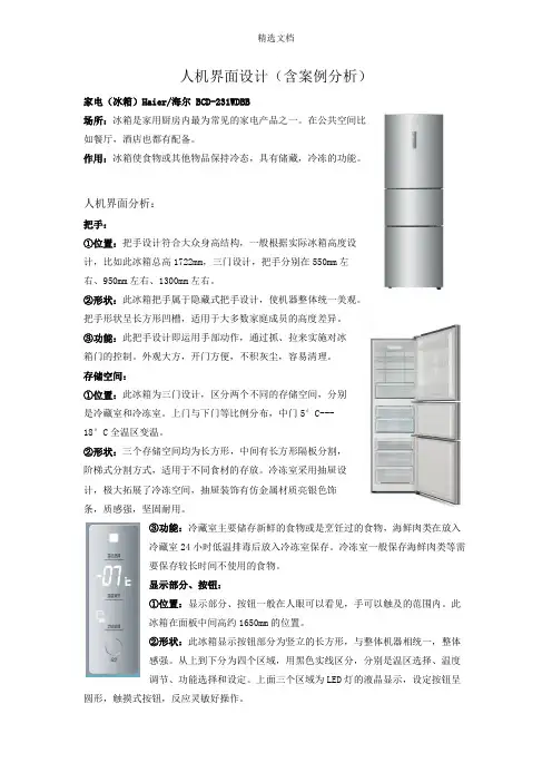
人机界面设计(含案例分析)家电(冰箱)Haier/海尔 BCD-231WDBB场所:冰箱是家用厨房内最为常见的家电产品之一。
在公共空间比如餐厅,酒店也都有配备。
作用:冰箱使食物或其他物品保持冷态,具有储藏,冷冻的功能。
人机界面分析:把手:①位置:把手设计符合大众身高结构,一般根据实际冰箱高度设计,比如此冰箱总高1722mm,三门设计,把手分别在550mm左右、950mm左右、1300mm左右。
②形状:此冰箱把手属于隐藏式把手设计,使机器整体统一美观。
把手形状呈长方形凹槽,适用于大多数家庭成员的高度差异。
③功能:此把手设计即运用手部动作,通过抓、拉来实施对冰箱门的控制。
外观大方,开门方便,不积灰尘,容易清理。
存储空间:①位置:此冰箱为三门设计,区分两个不同的存储空间,分别是冷藏室和冷冻室。
上门与下门等比例分布,中门5°C---18°C全温区变温。
②形状:三个存储空间均为长方形,中间有长方形隔板分割,阶梯式分割方式,适用于不同食材的存放。
冷冻室采用抽屉设计,极大拓展了冷冻空间,抽屉装饰有仿金属材质亮银色饰条,质感强,坚固耐用。
③功能:冷藏室主要储存新鲜的食物或是烹饪过的食物,海鲜肉类在放入冷藏室24小时低温排毒后放入冷冻室保存。
冷冻室一般保存海鲜肉类等需要保存较长时间不使用的食物。
显示部分、按钮:①位置:显示部分、按钮一般在人眼可以看见,手可以触及的范围内。
此冰箱在面板中间高约1650mm的位置。
②形状:此冰箱显示按钮部分为竖立的长方形,与整体机器相统一,整体感强。
从上到下分为四个区域,用黑色实线区分,分别是温区选择、温度调节、功能选择和设定。
上面三个区域为LED灯的液晶显示,设定按钮呈圆形,触摸式按钮,反应灵敏好操作。
③功能:此冰箱显示按钮部分采用电脑控温,冷藏冷冻的温度可通过设定按钮进行分开调节,并有记忆报警功能。
温区选择显示三个白色正方形灯光上下分布,温度调节显示白色摄氏温度,功能选择显示智能、假日、省电图形加文字三个功能。

人机对话和工业大数据产品选型手册ALWAYS IN INDUSTRIAL AUTOMATION中国华南:广东省佛山市南海区简平路1号天安科技大厦1305工厂:广东省佛山市南海区简平路1号天安时代大厦0101网站:USA:AMERICAN SCIENTIFIC KNOWLEDGE INCNY:228 PARK AVENUE, S#85556, NEW YORK, NY 10003,CA:3592 ROSEMEAD BLVD, STE B#220, ROSEMEAD, CA91770ASK工业自动化(中国)经销商ASK INDUSTRIAL AUTOMATION|ASK品牌保留随时更改资料信息的权利|RASK 专注工业自动化,科研开发人员长期植根企业现场,为客户研发、设计符合实际需求,操作简单、使用方便、功能稳定的产品。
ASK 切合实际的便捷软件及自动化产品,简化开发、加快效率,缩短产品上市时间;ASK 不断开发着方便大众的工业自动化产品。
人机对话产品:HMI、工业计算机、工业平板电脑、组态软件机器视觉产品:工业级摄像机、控制器、镜头、光源、平板显示器传动控制产品:变频器、伺服驱动及电机、高速精密主轴电机、步进控制器专用控制产品:卷绕、电子称重、裁切、温度控制器R生产组装老化测试ASK 工业自动化ASK 自动化产品应用于典型项目工程、机械配套、电气革新。
如:安联 、霍尼韦尔 、惠而浦、伟创力、高露洁 、德昌电机 、显示、京东方、 中国南水北调工程、广业集团等企业及项目。
工业级人机界面注1:AST-043A 通讯口为5pin 端子接头,其中COM2为选购项。
注2:AST-070A 只可扩展F1-F6前置按键,AST-043A 不可扩展前置按键。
注3:可选UL 认证规格。
工业级人机界面OEM 定制1.一体机:HMI+PLC2.前置USB 接口3.前置功能键4.定制外接键盘1.以太网2. Micro SD 插座3. RS232串口4. RS485/422串口5.音频输出接口6.影像输入接口形式多样丰富接口选择ASK 触摸屏选型表7. CAN 总线接口 8. VNC 网络远程监控9. U 盘,USB 下载USB 鼠标,USB 键盘, USB 打印机等等5.手握式设计6.VESA 安装设计7.裸机提供8.接受定制模块化直线或曲线动态实时拟和,随调节范围变化而放大缩小,区域微调和重量补正,动态显示当前运作点位,定点选择,模拟走线,修改确认,曲线调整完成后将点数+控制参数存入PLC 控制区。
人机界面操作使用说明山东鲁能积成电子股份有限公司2002年8月目录1.运行人机界面 (1)1.1.人机界面启动 (1)1.2.人员登记 (1)1.3.退出人机界面模块 (2)2.控制台窗口 (3)2.1.控制台窗口总览 (3)2.1.1.基础样式 (3)2.1.2.命令行样式 (3)2.2.命令行操作 (5)2.3.控制台工具栏 (6)2.3.1.系统设置与维护菜单总揽 (7)2.3.2.系统功能设置 (8)2.3.3.人员设置菜单 (14)2.3.4.口令设置菜单 (15)2.3.5.报警设置菜单 (15)3.索引图介绍 (17)3.1.索引图总揽 (17)3.2.定制索引图 (17)4.系统图形的调出 (19)4.1.调出总索引图 (19)4.2.其它任意图形的调出 (19)4.3.循环调图操作 (20)5.系统菜单命令 (21)5.1.图形漫游、浏览、打印等基本操作 (21)5.2.查询统计态操作 (23)5.3.设备信息浏览 (26)5.4.设备定位 (27)5.5.事故追忆 (28)5.6.故障模拟操作 (28)6.命令操作 (31)6.1. 遥测操作 (31)6.2. 对位操作 (33)6.3. 设备操作 (34)6.3.1.开关、刀闸操作 (34)6.3.2.变压器操作 (43)6.3.3.馈线操作 (44)7.曲线图操作 (44)8.事项窗浏览 (46)9.地理信息图操作说明 (47)9.1.进入地理信息图 (47)9.2.地理信息图的地图操作 (47)9.2.1.地理图操作主菜单 (47)9.2.2.主菜单操作项介绍 (48)9.3.地理信息图的实时信息及操作 (56)9.4.地理图文件的复制及实时数据初始化 (58)1.运行人机界面1.1.人机界面启动在人机界面没有启动的情况下,点击桌面iESDMS文件夹中的DMSMMI快捷方式或者在C:\IESDMS\BIN\目录下的DMSMMI.EXE文件名上双击就可以进入配网人机界面操作环境。
MT600/8000系列触摸屏人机界面MT-6056i安装说明目录一、前言为充分发挥本产品的卓越性能及确保使用者和设备的安全,在使用之前,请详细阅读本手册。
本使用手册为随机发送的附件,使用后请务必妥善保管,以备今后对控制器进行检修和维护时使用。
如对于本控制器的使用存在疑问或有特殊要求,请随时联络本公司,也可直接与本公司售后服务中心联系。
本手册内容如有变动,恕不另行通知。
1.1 主要功能特点1.液晶汉字参数显示、设定一目了然,故障时弹出故障内容、公司名称、服务电话。
2.可实现多达6台主泵+1台小泵或3台主泵+1台小泵的自动控制,每台水泵均可设为变量泵或定量泵(备用变量泵或备用定量泵),灵活配置,全面满足各种复杂的供水或消防系统。
3.定时换泵功能,使各泵工作时间均衡,提高水泵平均使用寿命。
4.具有消防泵巡检功能,在消防模式下根据设定时间对消防泵定时巡检,有效防止消防泵锈蚀。
5.多达8个时段压力控制,且每个时段均可进行任意压力设定控制及实现定时开关机功能。
6.具有休眠功能和附属小泵功能,节能降耗,延长设备使用寿命。
7.具有第二目标压力设定和控制功能。
8.具有故障互投功能,主泵有故障后自动投入到备用泵工作。
9.具有正、负反馈功能选择,既可以用于供水,又可以用于抽水保持水位。
10.锅炉补水控制和泄压阀压力区控制,控制值任意设定。
11.具有超压、低水位、传感器断线、变频器故障等报警控制功能。
12.变频器出现故障后,可选择自动转入工频运行(压力区间控制)。
13.故障自动复位机制,延时可调。
14.具有故障查询功能,能查询最新的报警内容及时间,共记录十条故障信息。
15.适应性强,可适用于国内外种品牌变频器。
16.模拟、数字信号全部采用电隔离,抗干扰能力强。
17.具有完善的密匙功能。
18.RS-485通讯功能,标准的MODBUS通讯协议,便于与上位机联接,进行组态控制。
1.2 技术指标二、控制器的安装2.1 控制器的外形尺寸2.2控制器的安装安装时在控制柜前面板上开一个孔,将显示器镶嵌于前面板上后随机的坚固件锁定。
DTD-0010A-DMB-A0Graphic OSD DisplayDemo BoardUser ManualVersion 0.1INFORMATION FURNISHED BY INNOVISION IS BELIEVED TO BE ACCURATE AND RELIABLE. HOWEVER, NO RESPONSIBILITY IS ASSUMED BY INNOVISION FOR ITS USE, OR FOR ANY INFRINGEMENTS OF PATENTS, OR OTHER RIGHTS OF THIRD PARTIES THAT MAY RESULT FROM ITS USE. NO LICENSE IS GRANTED BY IMPLICATION OR OTHERWISE UNDER ANY PATENT OR PATENT RIGHTS OF INNOVISION.Document Number: 1‐M‐PAE3TD‐0001©2010 Copyright by InnoVision Electronics Ltd. Version 0.12/11版本記錄DisclaimerTHE CONTENTS OF THIS DOCUMENT ARE SUBJECT TO CHANGE WITHOUT NOTICE. INNOVISION ELECTRONICS RESERVES THE RIGHT TO MAKE CHANGES WITHOUT FURTHER NOTICE TO ANY PRODUCTS HEREIN TO IMPROVE RELIABILITY, FUNCTION OR DESIGN. INNOVISION DOES NOT ASSUME ANY LIABILITY ARISING OUT OF THE APPLICATION OR USE OF ANY PRODUCT OR CIRCUIT DESCRIBED HEREIN; NEITHER DOES IT CONVEY ANY LICENSE UNDER ITS PATENT RIGHTS, NOR THE RIGHTS OF OTHERS.CUSTOMERS ARE ADVISED TO CONSULT WITH INNOVISION ELECTRONICS OR ITS COMMERCIAL DISTRIBUTORS BEFORE ORDERING.Date Version Comments Author 2010/8/18 0.1Preliminary VersionJason DuC on f i d e nt i a l目 錄一、簡介............................................................................................................................4 二、功能概要.....................................................................................................................4 三、介面介紹.....................................................................................................................4 四、功能操作 (5)1.按鍵功能與開機介紹 (5) 按鍵板定義.........................................................................................................................5 開機菜單.............................................................................................................................5 2. 菜單操作說明 (6) 【Tuner 】...........................................................................................................................6 【DVD 】.............................................................................................................................7 【GPS 】.. (7)五、遙控器操作.................................................................................................................9 六、觸摸屏操作 (10) 【主選單】 (10)【觸控操作】 (10)聯絡我們 (11)C on f i d e nt i a lRESETAL330 ISP/DEBUGTOUCH PANELGraphic Engine I2C JUMPERGraphic Engine ISPSSEL1 JUMPERC on f ilaitneVideo的對比度、亮度和色彩飽和度。