AX4-5I配置手册
- 格式:pdf
- 大小:517.68 KB
- 文档页数:36

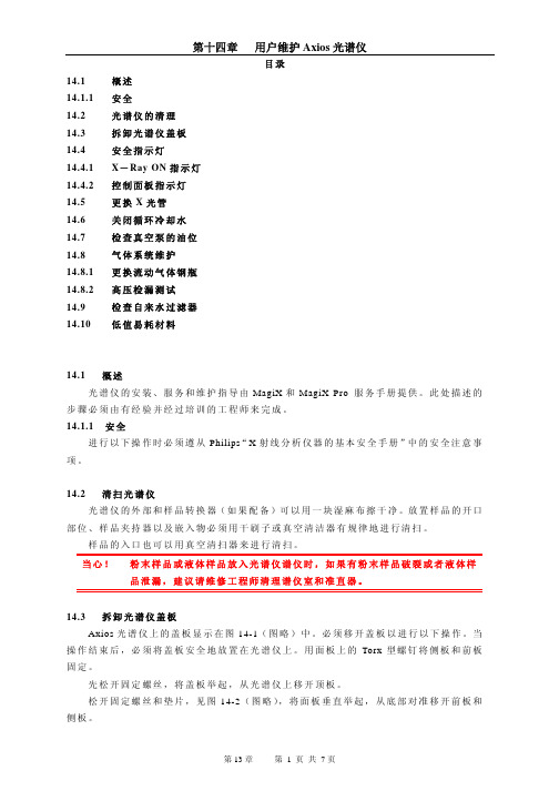
目录14.1 概述14.1.1 安全14.2 光谱仪的清理14.3 拆卸光谱仪盖板14.4 安全指示灯14.4.1 X-Ray ON指示灯14.4.2 控制面板指示灯14.5 更换X光管14.6 关闭循环冷却水14.7 检查真空泵的油位14.8 气体系统维护14.8.1 更换流动气体钢瓶14.8.2 高压检漏测试14.9 检查自来水过滤器14.10 低值易耗材料14.1 概述光谱仪的安装、服务和维护指导由MagiX和MagiX Pro 服务手册提供。
此处描述的步骤必须由有经验并经过培训的工程师来完成。
14.1.1 安全进行以下操作时必须遵从Philips“X射线分析仪器的基本安全手册”中的安全注意事项。
14.2 清扫光谱仪光谱仪的外部和样品转换器(如果配备)可以用一块湿麻布擦干净。
放置样品的开口部位、样品夹持器以及嵌入物必须用干刷子或真空清洁器有规律地进行清扫。
样品的入口也可以用真空清扫器来进行清扫。
当心!粉末样品或液体样品放入光谱仪谱仪时,如果有粉末样品破裂或者液体样品泄漏,建议请维修工程师清理谱仪室和准直器。
14.3 拆卸光谱仪盖板Axios光谱仪上的盖板显示在图14-1(图略)中。
必须移开盖板以进行以下操作。
当操作结束后,必须将盖板安全地放置在光谱仪上。
用面板上的Torx型螺钉将侧板和前板固定。
先松开固定螺丝,将盖板举起,从光谱仪上移开顶板。
松开固定螺丝和垫片,见图14-2(图略),将面板垂直举起,从底部对准移开前板和侧板。
14.4 安全灯此节讲述如何更换控制板和“X-Ray ON”顶灯。
所有的X-Ray ON指示灯和发光二极管指示灯组成安全回路,如果其中之一受到损坏,那么HT无法使用。
14.4 1. X-Ray ON 指示灯X-Ray ON 主指示灯中的灯泡有3对接线。
如果一个灯泡烧坏,则有一对熄灭。
建议用两个灯泡替换。
灯泡的更换:1. 将HT降到20kV/10mA,然后关闭;2. 在SuperQ软件内将介质转换为空气;3. 切断光谱仪电源;4. 如果安装了样品转换器,打开样品室的盖;5. 向上推,从X-Ray ON主指示灯上移走样品盖(盖是靠磁铁固定的);6. 松开并移走不工作的指示灯,更换新的灯泡;7. 打开光谱仪电源和HT(高压),简单检查灯是否亮;8. 再切断光谱仪电源和高压;9. 重新装上盖;10. 打开光谱仪电源和HT,使光谱仪返回到原先的状态;11. 等待机箱内温度稳定,然后操作光谱仪。

WIFI+网口版设备使用手册V1.5北京聚英翱翔电子有限责任公司版本说明版本说明V1.11、初始版本。
V1.21、增加了新版复位按钮说明。
V1.31、增加了新版TCP连接软件测试说明,不再需要使用虚拟串口方式;2、增加了查询当前网络信息的方法说明。
V1.41、使用新版WIFI网口通讯模块;2、更新新版WIFI模式配置参数说明;3、更新新版网口模式配置参数说明。
V1.51、更新优化参数配置目录一、软件说明 (1)二、工作模式 (1)1、WIFI模式 (1)2、网口模式 (1)三、硬件说明 (1)1、默认IP (1)2、复位键 (1)四、参数配置 (2)1、WIFI参数 (2)2、网口参数 (7)五、TCP/UDP模式 (15)1、WIFI配置 (15)2、网口配置 (16)六、通讯测试 (20)1、软件测试 (20)2、Socket网络测试工具 (21)3、Modbus TCP测试 (27)七、设备地址 (32)1、使用软件 (32)2、修改方法 (32)八、PLC通讯 (32)九、技术支持 (33)一、软件说明WIFI网口设备中的WIFI通讯参数和网口通讯参数分别设置,支持两种通讯方式分别设置,支持同时通讯。
WIFI参数:◆WIFI参数通过WEB界面进行参数配置;◆设备具有独立的AP热点信号:JY_***;◆支持直连热点信号通讯控制;◆支持接入局域网WIFI网络组网通讯;◆支持TCP/UDP Client/Server模式。
网口参数:◆通过以太网配置软件进行参数配置;◆支持直连/组网通讯;◆支持TCP/UDP Client/Server模式。
二、工作模式1、WIFI模式模式说明AP使用设备本身的热点信号WiFi设备WIFI桥接入用户无线路由器的WIFI信号中1AP模式:WiFi模块作为热点,可以用电脑或者手机连接上WiFi进行通讯,默认AP的名字为JY_XXXXXX,密码为12345678,默认IP为:192.168.10.1。


锐捷路由器配置手册目录:路由器基础:控制台远程登录其它配置方法命令模式命令模式的切换CLI命令的编辑技巧常见CLI错误提示使用 no 和 default 选项查看配置文件保存配置文件删除配置文件备份配置文件文件系统概述文件操作目录操作搭建环境用TFTP传输文件用Xmodem传输文件ROM监控模式路由器的基本配置:配置控制台口令配置远程登录口令配置特权口令以太网接口的一般配置配置多个IP地址配置MAC地址接口信息的查看同步串行口的一般配置配置反转时钟配置链路封装协议配置线路编解码方式忽略DCD信号接口信息的查看回环接口的配置接口信息的查看配置路由:配置静态路由配置默认路由配置缺省网络配置可被动态路由覆盖的静态路由RIP协议的一般配置RIP协议参数的配置OSPF协议的一般配置广域网协议配置:配置接口的HDLC封装配置keepalive时间配置接口的PPP封装配置PPP协商超时时间配置CHAP服务端配置CHAP客户端配置双向CHAP验证配置PAP服务端配置PAP客户端配置双向PAP验证点到点的帧中继配置NAT的配置:静态NAT的配置静态NAPT的配置动态NAT的配置动态NAPT的配置接口动态NAPT的配置外部源地址的静态NAT配置外部源地址的动态NAT配置DHCP的配置:启用DHCP服务器配置DHCP地址池配置选项访问控制列表的配置:标准ACLs的语句规则配置标号的标准ACLs配置命名的标准ACLs扩展ACLs的语句规则配置标号的扩展ACLs配置命名的扩展ACLsMAC扩展ACLs的语句规则配置标号的MAC扩展ACLs配置命名的MAC扩展ACLsExpert扩展ACLs的语句规则配置标号的Expert扩展ACLs配置命名的Expert扩展ACLs带序号的ACLs带时间区的ACLs第一部分路由器基础:路由器的几种配置方法控制台用一台计算机作为控制台和网络设备相连,通过计算机对网络设备进行配置。
1、硬件连接:把Console线一端连接在计算机的串行口上,另一端连接在网络设备的Console口上。


AX4-5磁盘阵列配置方式1.使用IE登录阵列使用网线连接磁盘阵列,打开lE浏览器,在地址栏中输入控制器地址并回车。
右侧机柜阵列SPA/SPB IP为:1.1.1.1/2。
输入用户名密码admin/password,并点击Login,进入管理界面。
2.设置Hotspare硬盘点击左侧菜单栏Management下面的Hot Spares,然后点击页面中显示的Create a hotspare链接,系统会显示出可以用作Hot Spare的硬盘。
选中作为Hot Spare的硬盘,点击Apply。
系统提示创建成功,可以点击ViewHot Spare details查看刚刚创建的热备磁盘属性。
如果要删除此热备磁盘,可以选择页面中的Destroy删除。
重复上述过程,可以创建多块Hot Spare磁盘。
3.创建Disk Pools点击Management—>Disk Pools,然后选择Create Disk Pool。
选择RAID类型选择磁盘然后点击Apply重复以上步骤,创建其他Disk Pool。
如果要扩展已存在的Disk Pool,则点击Manage Disk Pools,在页面右侧会列出系统中已存在的所有Disk Pool。
选中要进行扩展的Disk Pool,然后选择Expand 。
选中需要加入该Disk Pool的磁盘,然后点击Apply。
4.创建Virtual Disks选择Manage Virtual Disks,然后选择Create Virtual Disk。
选择Disk Pool。
输入Virtual Disk名称、大小,如果一次创建多个同等容量的Virtual Disk,则可以在Number of Virtual Disk中填入数目。
如果当前磁盘阵列没有连接主机,则在Step 3中讲Server项选为None。
点击Apply完成创建。
5.服务器安装软件在服务器安装Navisphere Server Utility和Powerpath软件。
®ELECTRONIC DEADBOLT & LEVER LOCKLS-5i USER MANUALATTENTION: Please do not use an “electronic screwdriver” for installation1INSTALLATIONS INSTRUCTIONS1. CONFIGURE LATCH BACKSETThe BACKSET is the distance between the center of cross bore and edge bore of the door.Adjustable latch fits both BACKSET of 2-3/8” (60mm) and 2-3/4” (70mm). Please follow the steps shown below for BACKSET adjustment.DEADBOLT BACKSETRotate the latch case as diagram on the right for backset 2-3/4” (70mm) or reverse direction for 2-3/8” (60mm).LEVER BACKSETThe backset shown on the left is 60mm (2-3/8”).Pull the cam toward right to extend the backset to 70mm (2-3/4”).The backset shown in figure C is 70mm (2-3/4”). Pull the cam back to left will return the backset to 60mm (2-3/8”).Note : The shape of cam should be square.23. INSTALL LATCH4. INSTALL STRIKEInsert the latch and tighten it with screws. Please use “tapping screws” for metal doors.Insert the strike and tighten it with screws.Please use “tapping screws” for metal frames.2. IDENTIFY DOOR HANDINGFace the door from outside, the door is left-handed if the hinge is on the left-hand side of the door, whereas the door is right-handed if the hinge is on the right-hand side of thedoor.INTERIOREXTERIOR (Left-handed)(Right-handed)36. INSTALL INSIDE MOUNTING PLATE5. INSTALL KEYPAD ASSEMBLYPass the IC wire through the wire hole on the mounting plate and affix the mounting plate with screws. If outside lock assembly is lopsided, please loosen the screws to adjust it’s position and tighten the screws again.Place the leverset against keypad with tailpiece in vertical position inserted through cam of the latch.Ensure the latch bolt is retracted.Pass the IC wire under the latch to the interior side of the door.Pass the IC wire over the latch to the interior side of door.Please refer to diagram B for cylinder installation.Place deadbolt against keypad with tailpiece in horizontal position inserted through hub of the latch.OUTSIDE LEVERCYLINDERDEADBOLT KEYPAD ASSEMBLYLEVER KEYPAD ASSEMBLY4TURN PIECE7. INSTALL RECEIVER MODULEAdjust turn piece as shown in diagram A.Remove the battery cover (push it up and pull it out).Connect the IC wire then attach receiver module to the door with screws. It’s optio nal to use the included wood screw (wood screw only for wood doors).Remove the battery cover (push it up and pull it out).Connect the IC wire then attach reciever module to the door with screws. It’s optional to use the included wood screw (wood screw only for wood doors).DEADBOLT RECEIVER INSTALLLEVER RECEIVER INSTALL(Right HandedDoor)(Left HandedDoor)WOOD58. INSTALL BATTERIES9. CHANGE LEVER HANDINGInsert 4 AA Alkaline or Lithium batteries and put the battery cover back on the receiver module.Do not use rechargeable (NiCD, NiHM, LiPo, etc.) batteries or batteries with a voltage rating of under/over 1.5v * Please Note: Deadbolt model will not function until door handing is programmed on the lock (pg.8)Be sure the levers are unlocked.Insert the provided pin wrench into the small hole on the neck of lever and apply pressure to depress the catch and pull out the lever from the stem.Follow the same steps to remove interior lever and exchange the position of inside and outside levers.Remove the cylinder from lever and insert it into opposite lever.Then install the levers and make sure the small hole on the neck of lever aligns over the catch perfectly. Rotate the levers to see if it operates well.6LOCK OVERVIEWLOCKSTATE BUTTONThe LockState Button is utilized for entering codes and setting functions. It’s also a lock button.NUMBER BUTTONSInput buttons for codes and function programming.CYLINDERLock/Unlock the lockset from exterior.GASKETPrevent water permeating into lockset.BATTERY LIDSlide the lid to change the batteries.BATTERY HOLDERFour AA (1.5v) Alkaline or Lithium batteries only.R BUTTON (RESET)Restores default settings.TURN-BUTTONLock/Unlock the lockset from interior.7SPECIFICATIONS/FUNCTIONSPower: 6v, four AA (1.5V) Alkaline or Lithium batteries only. Low battery warnings at4.25V and 3.75VProgramming Code (PC): The preset programming code is 123456. Please change it to a new code for security. Programming code length is 4-10 digits.Local Codes: Codes that are programed using the programming code at the lock. There is a limit of 10 in memory and the code 1234 is programmed by default. Local codelengths are 4-10 digits.User Codes: Codes that are programed using the web portal and can be configured to follow an access schedule. User code lengths are 4-10 digits.Auto-Lock / Storehouse Mode: The lock will automatically relock itself after the speci-fied delay following an unlock. Default delay is 5 seconds. Enabled by default on all lever models.Passage Mode: The lock will remain unlocked after a code is entered. Enabled by default on all deadbolt models.Audio Indications1 beep indicates successful operation or button press2 beeps indicates successful programming3 beeps indicates operational or programming error4 beeps indicates 4.25V low battery warning8 beeps indicates 3.75V low battery warningIlluminated Indications1 green flash indicates successful operation or button press2 green flashes indicates successful programming3 red flashes indicates operational or programming error4 red flashes indicates 4.25V low battery warning8 red flashes indicates 3.75V low battery warningOrange flashes indicates lock is in the middle of a programming sequence Restore Factory DefaultsPreset factory settings can be restored by pressing and holding the “R” button on thebattery pack within 10 seconds of power cycling the lock (removing and reinserting asingle battery).Deadbolt Door HandingDirectional instructions for the deadbolt to correctly set locked/unlocked positions.Required programming during initial setup or after a factory reset for deadbolt models only.Unlocking the doorThe lockset will become unlocked by key, by entering a user/local code followed byLockState on the keypad, or by interior turn knob.Locking the doorThe lockset will become locked by key, by pressing the LockState button twice, or byinterior turn knob.8FUNCTION PROGRAMMINGSet Door Handing (Deadbolt only)NOTE: Place deadbolt in the “unlocked” position for this step. The lock will not operate until this setting has been programmed during initial setup or after factory reset.Enter PC 140Enter PC 100 Enter New PC Enter PC 110 Enter New LC Enter PC 120 Enter LC Delete All Local CodesNOTE: This will place the default local code 1234 back into memory.Enter PC 131Enter PC 117 Press RB Enter PC 118 Enter PC 312 Enter PC 271Enter PC 260 Enter Delay Enter PC 270Enter PC 160 Enter PC 161Programming Code(Default: 123456)Local Code Remote ButtonPC:LC:RB:ELECTRONIC DEADBOLT & LEVER LOCKQUICK START GUIDEINSTALL LOCKRefer to pages 1-4 for installationSET DOOR HANDING (DEADBOLT LOCK ONLY)NOTE: Place deadbolt in the “unlocked” position for this step. Lock may not operate until this setting has been programmed during initial setup or after factory reset. Default Programming Code is 123456.WI-FI PROVISIONINGRefer to the separate Provisioning Guide for instruc-tions on setting up the lock to connect to your Wi-Fi network for internet access.OPERATING THE LOCKUnlocking the doorThe lockset will become unlocked by entering a user/local code on the keypad followed by LockState, by key, or by interior turn knob.Locking the doorThe lockset will become locked by pressing the Lock-State button twice, by key, or by interior turn knob.。
刀片式服务器:1. Power Edge M910 4插槽全高刀片式服务器2. Power Edge M710 双插槽、Intel 双核和四核全高刀片式服务3. Power Edge M610双插槽、Intel双核和四核半高刀片式服务器4. Power Edge M1000e 10U模块化刀片式机箱,针对Dell刀片式服务器而优化5. Power Edge M905最高配置六核AM映理器四路4U机架式服务器6. Power Edge M805最高配置六核AM映理器的双路2U机架式服务器7. Power Edge M605最高配置六核AM映理器的双路半高刀片式服务器8. Power Edge M600四核刀片式服务器机架式服务器:1. Power Edge R200 单插槽1U机架式服务器2. Power Edge R210是戴尔推出的一款超值入门级单插槽1U机架式服务器3. Power Edge R300引进了一种专用于卓越性能和高可用性功能的新型、高级单插槽芯片组和处理器4. Power Edge R805 的内存和I/O可扩展性是前一代标准2U双插槽服务器的2倍5. Power Edge R710专门依据客户需求量身打造。
6. Power Edge R610 具有了戴尔的系统通用性7. Power Edge R510是一款双插槽2U机架式服务器,具备高级管理功能、8. Power Edge R410是一款功能强大的双插槽1U服务器,非常适合用于在空间有限的数据中心或HPCg境中运行计算密集型应用程序。
9. Power Edge 2970 双插槽支持四核AMD皓龙处理器及AM或动态电源管理功能10. Power Edge R905是专为提高性能、简化虚拟化部署而设计。
11. Power Edge R900采用6核处理,进一步增强了戴尔业界领先的虚拟化性能12. Power Edge R810是一款高密度、4插槽或2插槽2U机架式服务器,13. Power Edge R910™是一款高性能4插槽4U机架式服务器,它具备内置可靠性与可扩展性,适用于关键任务应用程序。
CX3UltraScale™系列、CX系列、AX4–5系列和AX150系列用于Windows的iSCSI服务器安装指南P/N300–004–870,修订版A062007年11月19日本文档介绍如何在服务器上配置iSCSI启动器端口和设置iSCSI安全,这些服务器与CX3UltraScale TM系列、CX系列、AX4–5系列和AX150系列存储系统上的iSCSI数据端口相连。
建议您将本指南与存储系统设置指南(带有Navisphere Express的AX4–5系列、CX3系列或CX系列存储系统)、存储系统入门指南(带有Navisphere Express的AX150系列存储系统)或安装指南(带有Navisphere Manager的AX4–5系列或AX150系列、CX3系列或CX系列存储系统)一起使用。
存储系统设置指南、入门指南和安装指南(P/N069001166)在Powerlink网站上可以找到。
本文档中的术语“CX3系列”是指CX3型号10系统、CX3型号20系统、CX3型号40系统及CX3型号80系统,而术语“CX系列”是指CX200、CX300系列、CX400、CX500系列、CX600及CX700存储系统。
本文档还使用术语“AX4-5系列”来指AX4-5SC、AX4-5SCi、AX4-5、AX4-5i存储系统,用术语“AX系列”来指AX150系列系统(包括AX150SC、AX150SCi、AX150和AX150i)。
有关支持的操作系统版本、驱动程序类型或功能的信息,请参阅Powerlink网站上的E-Lab™Interoperability Navigator(针对CX3系列或CX系列存储系统),以及存储系统技术支持网站安装页面上的SupportMatrix链接(针对AX4-5系列或AX系列存储系统)。
本文档包括以下主题:准备工作 (3)iSCSI服务器设置过程概述 (5)安装NIC或HBA iSCSI启动器软件 (6)为NIC或iSCSI HBA分配IP地址 (9)安装Navisphere Server Utility(仅限于NIC启动器) (10)修改TCP/IP注册设置 (13)配置NIC或iSCSI HBA启动器 (15)准备使用CHAP安全 (24)在iSCSI启动器上配置CHAP (26)1修改服务器上的CHAP凭据 (34)2用于Windows的iSCSI服务器安装指南准备工作使用本指南在服务器上设置iSCSI启动器端口或设置iSCSI安全(挑战握手认证协议-CHAP)之前,您必须:按照存储系统设置指南、存储系统入门指南或安装指南(仅限于带有Navisphere Manager的存储系统)中的说明配置存储系统iSCSI端口。
完成存储系统附带的或从存储系统技术支持网站定制生成的存储系统配置规划指南中的工作表。
对于AX4-5系列或AX150系列,可使用存储系统技术支持网站安装页上的规划链接生成规划指南。
对于CX3系列或CX系列,可使用存储系统技术支持网站上的规划链接生成规划指南。
有关CHAP的详细信息,请参见以下各部分。
否则,请参阅iSCSI服务器设置过程概述(第5页)。
CHAP概述挑战握手认证协议(CHAP)是对iSCSI用户进行身份验证的一种方法。
iSCSI存储系统可以使用CHAP验证启动器,同样,启动器也可以对目标(如存储系统)进行验证。
注意如果不为存储系统配置CHAP,那么任何连接到存储系统iSCSI端口所在IP网络的主机都可以对存储系统进行读取和写入操作。
如果存储系统位于一个专用网络上,可以选择不使用CHAP。
如果存储系统位于一个公共网络上,则强烈建议您使用CHAP。
如果要使用CHAP,必须在准备用来接收数据的LUN或虚拟磁盘之前,在服务器和存储系统上均设置并启用CHAP。
如果在设置并启用CHAP之前准备用来接收数据的磁盘,将无法访问LUN或虚拟磁盘。
设置并启用CHAP时,服务器和存储系统之间的连接可能会临时断开。
用于Windows的iSCSI服务器安装指南3CHAP有两种类型-启动器CHAP和双方CHAP:启动器CHAP-设置iSCSI启动器用于连接到目标的帐户。
目标对启动器进行身份验证。
启动器CHAP是主要的CHAP身份验证方法。
Navisphere Express提供了初级和高级两种启动器CHAP选项。
初级CHAP为所有登录到指定目标的启动器指定同一个密码。
高级选项允许您为每个启动器指定不同的密码,且允许您设置双方CHAP。
双方CHAP-用于启动器CHAP之外的情形,双方CHAP可设置目标用来连接到启动器的帐户。
启动器对目标进行身份验证。
4用于Windows的iSCSI服务器安装指南iSCSI服务器设置过程概述以下概述了配置iSCSI启动器端口以及设置iSCSI安全所需的步骤。
配置iSCSI启动器端口❑在具有要连接到存储系统的网络接口卡(NIC)或iSCSI主机总线适配器(HBA)的每台服务器上安装NIC或HBA iSCSI启动器软件,如安装NIC或HBA iSCSI启动器软件(第6页)中所述。
❑为NIC或iSCSI HBA分配IP地址,如为NIC或iSCSI HBA分配IP地址(第9页)中所述。
❑如果Windows服务器上安装有Microsoft NIC Initiator,请安装Navisphere®Server Utility。
您将使用该Server Utility配置iSCSI连接和双方CHAP(可选)。
❑为NIC或HBA iSCSI启动器配置启动器网络参数,如配置NIC或iSCSI HBA启动器(第15页)中所述。
设置iSCSI安全❑准备在服务器上设置CHAP,如准备使用CHAP安全(第24页)中所述。
❑在每个NIC或iSCSI HBA启动器上配置启动器和双方(可选)CHAP,在iSCSI启动器上配置CHAP(第26页)中有相关说明。
用于Windows的iSCSI服务器安装指南5安装NIC或HBA iSCSI启动器软件您必须在将要连接到存储系统的每台带有NIC或iSCSI HBA的服务器上安装NIC或iSCSI HBA启动器软件。
对于NIC,请按照下载并安装Microsoft iSCSI Software Initiator(第6页)中的说明安装Microsoft iSCSI Software Initiator。
必须安装Microsoft iSCSI Software Initiator,因为Navisphere Server Utility要使用它来配置iSCSI连接。
对于iSCSI HBA,则请按照下载并安装Microsoft iSCSI SoftwareInitiator(第6页)中的说明安装Microsoft iSCSI Software InitiatorService选项,然后按照下载并安装适用于iSCSI HBA的QLogicSANsurfer软件(第8页)中的说明安装QLogic SANsurfer软件。
必须安装Microsoft iSCSI Software Initiator的启动器服务选项,因为QLogic驱动程序需要该功能。
下载并安装Microsoft iSCSI Software Initiator1.打开一个Web浏览器并连接到Microsoft网站:http://www.mi-2.转至Downloads页面。
3.搜索iscsi initiator。
4.选择并下载最新的受支持启动器软件和相关文档。
有关CX3系列或CX系列存储系统支持的软件的信息,请参阅Powerlink网站上的E-Lab™InteroperabilityNavigator:。
有关AX4–5系列或AX系列存储系统上支持的软件的信息,请参阅存储系统技术支持网站安装页上的Support Matrix,或参阅存储系统技术支持网站的“技术说明”部分中的支持的配置。
要确定下载的文件:6用于Windows的iSCSI服务器安装指南a.在我的电脑上单击右键,然后选择管理。
b.选择系统信息>系统摘要。
c.查看系统类型选项。
如果显示x86,则说明您使用的是32位系统。
如果显示IA64或AMD64,则说明您的系统是64位系统,需要安装相应的64位版本(IA或AMD)。
5.下载适当的软件之后,双击可执行文件打开安装向导,并单击“欢迎使用”屏幕中的下一步。
6.根据正在运行的PowerPath版本,在安装选项屏幕上选择以下版本之一:PowerPath iSCSI不再适用于CX3系列和CX系列存储系统。
PowerPath4.6或更高版本(AX4–5、CX3和CX系列)和PowerPath iSCSI1.1或更高版本(AX150和AX100系列)使用PowerPath4.6或更高版本,只有在启动器位于Windows Server2003服务器时,才选择Microsoft MPIO Multipathing Support for iSCSI。
NIC-选择Initiator Service、Software Initiator和Microsoft MPIO Multipathing Support for iSCSI,然后单击下一步。
如果未选中Microsoft MPIO Multipathing Support for iSCSI选项,安装程序会尝试卸载Microsoft iSCSI DSM和核心MS MPIO文件。
但是,如果已经安装其他DSM,例如包括PowerPath4.6或更高版本的DSM,则不会卸载核心MS MPIO文件。
安装向导会检查MS MPIO支持设备列表,来确定是否安装了其他的DSM。
iSCSI HBA-选择Initiator Service和Microsoft MPIOMultipathing Support for iSCSI,然后单击下一步。
请不要选择iSCSI HBA的Software Initiator。
PowerPath4.5.1或更低版本用于Windows的iSCSI服务器安装指南7NIC-选择Initiator Service和Software Initiator,然后单击下一步。
请不要选择Microsoft MPIO Multipathing Support for iSCSI。
iSCSI HBA-选择Initiator Service,然后单击下一步。
请不要选择Microsoft MPIO Multipathing Support for iSCSI或Software Initiator。
7.阅读并接受许可协议,然后单击下一步安装软件。
8.如果是安装新软件,请在完成屏幕上单击完成。