ITARGE-COMS高清抓拍机_使用手册_V1.0
- 格式:pdf
- 大小:1.10 MB
- 文档页数:21
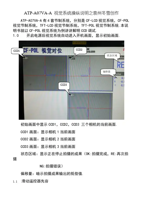
ATP-A07VA-A 视觉系统操纵说明之袁州冬雪创作ATP-A07VA-A有4套节制系统,分别是CF-LCD视觉系统,CF-POL 视觉节制系统,TFT-LCD视觉节制系统,TFT-POL视觉节制系统.本说明书就以CF-POL视觉系统为例讲讲解明CCD调试.1.0 开启电源后视觉系统自动进入开机画面,显示初始画面.CCD1 CCD2状态区域偏移量CCD3初始画面中显示CCD1,CCD2,CCD3 三个相机的当前画面.CCD1画面:显示相机1当前画面CCD2画面:显示相机2当前画面CCD3画面:显示相机3当前画面状态区域:显示正在停止拍摄的成果(OK:拍摄完成,RE:再次拍摄NG:拍摄错误)偏移量:暗示拍摄成果输出的抵偿值.1.1滑动遥控器先容1号按键 FUNCTION (功能键)切换功能菜单的显示和非显示 2号按键 ESCAPE (退出键)设定时返回前面一个界面或者退出 3 号按键 TRIGGER (拍摄键) 一齐输入触发4号按键 SCREEN (屏幕键) 按顺序切换现在显示的画面的显示种别5 号按键VIEW (画面切换) 显示检查栏,切换画面的扩展/缩小,显示形式6 号按键 MENU (主菜单) 更改对话框菜单的浓度7号按键 (调试功能) 在流程编辑画面中切换通常显示/扩展显示1.2 进入操纵权限按下按键1,弹出功能菜单对话框,移动光标至实用功能,进入对话框,选择用户帐号切换,弹出用户帐号切换对话框.用户选择框中选择Administlator,用户暗码是2222 .点击OK ,进入操纵权限了.1.3 建立视觉模板 OK 按键 7号按键RUN/STOP 键 光标按键视觉模板是视觉系统在生产中比对各种分歧位置产品的模板,所以建立模板是必须选择轮廓了了,概况清洁的产品.建立模板的产品必须放置在视觉图片的中央位置,便于视觉系统疾速比对产品.进入权限后,按遥控器反面7号按键,进入Main菜单.一共有4步和选项,(STEP3和STEP4出厂设置OK不必更改)STEP1 相机设定点击STEP1,进入相机设定画面,可供选择每一个相机的设定.在此,选择相机1举例.快门速度(ms)相机感度根据图像的清晰程度,调节快门速度和相机感度,使图像轮廓显示清晰了然.STEP2 搜索设定搜索设定主要是建立模板,点击搜索设定,进入设定画面,有所有相机的设定,在此以相机1设定为例 .相机1设定分为三部分,相机1搜索设定(注:CF-LCD, TFT-LCD视觉系统中有边沿搜索和轮廓搜索功能选择,CF-POL,TFT-POL中只有边沿搜索设定.),相机1边沿设定(横边),相机1边沿设定(竖边).进入相机1搜索设定相机1搜索设定图像注册:在下拉列表中选择当前图像,点击图像注册,将当前视觉画面中的图像注册为相机模板.搜索范围:点击搜索范围,进入选定对话框,选择矩形圈中注册图像中要搜索的图像范围.搜索对象:即产品中的MARK特征的区域内 .进入搜索对象画面中,在检测范围下拉菜单中选择矩形,编辑矩形大小,圈中MARK特征区域.预处理:对搜索图像的预处理.(根据图像的清晰程度选择是否需要停止预处理)预处理有二值化,对比度转化,膨胀,收缩,恍惚处理等方法,根据需要选择适合的方法.相机1边沿设定(横)相机1边沿设定(横):即对选定的MARK区域的MARK点的横边设定.设定内容包含范围设定,预处理和检测条件.范围设定:设定MARK点的横边的范围,用蓝色的矩形圈中非常分明的MARK特征.以便自动运行时对比特征的确定.若图像中有很多相似的MARK特征或者图像不清晰,可以选用屏蔽框把干扰的部分屏蔽.预处理:即对圈中的MARK点的横边范围做处理,消除轮廓不清晰,毛刺突出,黑白不敷分明等.此处预处理方式和相机1搜索设定预处理方式相同.检测条件:即设定视觉系统对每一个产品的对比方式,主要检测方向和边沿方向.在下图中,蓝色矩形圈中MARK特征,设置检测方向是有下到上,在图像中的颜色是白色过度到黑色,故我们设置的边沿方向是由明到暗.相机1边沿设定(竖边)设定和相机1边沿设定(横边)相同.选项:选项中主要设定断定公差/偏移和画面显示断定公差是指视觉节制系统的节制精度节制在一个什么范围内.偏移公差是指视觉节制系统中人工增加的一个偏移量.画面显示是指显示器中画面的显示方式.(出厂都设置为持续)。

Illustra Essentials Indoor / Outdoor HD Mini Dome with IRUser Manual 8200-1102-04 C0NoticePlease read this manual thoroughly and save it for future use before attempting to connect or operate this unit.The information in this manual was current when published. The manufacturer reserves the right to revise and improve its products. All specifications are therefore subject to change without notice.CopyrightUnder copyright laws, the contents of this manual may not be copied, photocopied, reproduced, translated orreduced to any electronic medium or machine-readable form, in whole or in part, without prior written consent of Tyco Security Products. © 2015 Tyco Security Products. All rights reserved.Customer ServiceThank you for using Tyco Security Products. We support our products through an extensive worldwide network of dealers. The dealer through whom you originally purchased this product is your point of contact if you needservice or support. Our dealers are empowered to provide the very best in customer service and support.Dealers should contact Tyco Security Products at (800) 507-6268 or (561) 912-6259 or on the Web at.TrademarksThe trademarks, logos, and service marks displayed on this document are registered in the United States [orother countries]. Any misuse of the trademarks is strictly prohibited and Tyco Security Products. willaggressively enforce its intellectual property rights to the fullest extent of the law, including pursuit of criminalprosecution wherever necessary. All trademarks not owned by Tyco Security Products. are the property of their respective owners, and are used with permission or allowed under applicable laws.Product offerings and specifications are subject to change without notice. Actual products may vary fromphotos. Not all products include all features. Availability varies by region; contact your sales representative.Important Safeguards and Warnings 1.Electrical safetyAll installation and operation should conform to your local electrical safety codes.The power shall conform to the requirement in the SELV (Safety Extra Low Voltage) and the Limited power source is rated 12V DC or 24V AC in the IEC60950-1. (Refer to general introduction)Please note: Do not connect two power supplying sources to the device at the same time; it may result in device damage! The product must be grounded to reduce the risk of electronic shock.We assume no liability or responsibility for all the fires or electrical shock caused by improper handling or installation.We are not liable for any problems caused by unauthorized modification or attempted repair. 2.Transportation securityHeavy stress, violent vibration or water splash are not allowed during transportation, storage andinstallation.3.InstallationDo not apply power to the camera before completing installation.Please install the proper power cut-off device during the installation connection.Always follow the instruction guide the manufacturer recommended.4.Qualified engineers neededAll the examination and repair work should be done by the qualified service engineers.We are not liable for any problems caused by unauthorized modifications or attempted repair. 5.EnvironmentThis series network camera should be installed in a cool, dry place away from direct sunlight,inflammable, explosive substances and etc.Please keep it away from the electromagnetic radiation object and environment.Please make sure the CCD (CMOS) component is out of the radiation of the laser beam device.Otherwise it may result in CCD (CMOS) optical component damage.Please keep the sound ventilation.Do not allow the water and other liquid falling into the camera.Thunder-proof device is recommended to be adopted to better prevent thunder.The grounding studs of the product are recommended to be grounded to further enhance the reliability of the camera.6. Daily MaintenancePlease shut down the device and then unplug the power cable before you begin daily maintenance work.Do not touch the CCD (CMOS) optic component. You can use the blower to clean the dust on the lens surface.Always use the dry soft cloth to clean the device. If there is too much dust, please use the water to dilute the mild detergent first and then use it to clean the device. Finally use the dry cloth to clean the device.Please put the dustproof cap to protect the CCD (CMOS) component when you do not use the camera.Dome enclosure is the optical component, do not touch the enclosure when you are installing the device or clean the enclosure when you are doing maintenance work. Please use professional optical clean method to clean the enclosure. Improper enclosure clean method (such as use cloth) may result in poor IR effect of camera with IR function.7. AccessoriesBe sure to use all the accessories recommended by manufacturer.Before installation, please open the package and check all the components are included.Contact your local retailer ASAP if something is broken in your package.Accessory Name AmountNetwork Camera Unit 1Quick Start Guide 1Installation Accessories Bag 1CD 1Table of ContentsImportant Safeguards and Warnings (iii)Table of Contents (v)General Introduction (1)Overview (1)Features (1)Specifications (2)Structure (5)Components (5)Framework and Dimension (6)Device Installation (7)Quick Configuration Tool (8)Overview (8)Operation (8)Web Operation (10)Network Connection (10)Login and Main Interface (10)FAQ (12)Appendix Toxic or Hazardous Materials or Elements (13)General Introduction OverviewThis series network camera integrates the traditional camera and network video technology. It adopts video data collection, transmission together. It can connect to the network directly without any auxiliary device.This series network camera uses standard H.264 video compression technology, which maximally guarantees the video quality.It supports the IR night vision function. In the night environments, the device can use the IR light to highlight the object which is suitable for the surveillance function in the low illumination environments.The waterproof design conforms to the IP 66 level. It has the sound waterproof function suitable for usein the outdoor environments.It can be used alone or used in a network area. When it is used lonely, you can connect it to the network and then use a network client-end. Due to its multiple functions and various uses, this series network camera is widely used in many environments such office, bank, road monitor and etc.FeaturesUser Management ●Different user rights for each group, one user belongs to one group.●The user right shall not exceed the group right.Storage Function ●Support central server backup function in accordance with your configuration andsetup in alarm or schedule setting●Support record via Web and the recorded file are storage in the client-end PC.●Support network storage function such as FTP.Network Monitor ●Network camera supports one-channel video data transmit to network terminaland then decode. Delaying time is within 270ms (network bandwidth support needed)●Max supports 20 connections.●Adopt the following video transmission protocol: HTTP, TCP, UDP, MULTICAST,RTP/RTCP, RTSP and etc.●Support web access.Network Management ●Realize network camera configuration and management via Ethernet.●Support device management via web or client-end.Power ●External power adapter DC 12V.●Some series support PoE.CAUTIONDo not connect these two power supplying sources to the device at the same time; it may result in device damage!Assistant Function ●Log function●Support system resource information and running status real-time display.●Day/Night mode auto switch.●Support picture parameter setup such as electronic shutter and gain setup.●Support motion detect.●Backlight compensation: screen auto split to realize backlight compensation toadjust the bright.●Support video watermark function to avoid vicious video modification.●Built-in IR light. Support IR night vision.●The enclosure conforms to the IP 66 protection. Has the waterproof function.SpecificationsNetwork Wire Network 1-ch 10/100 Base-T EthernetNetwork Protocol HTTP, TCP/IP, ARP,IGMP, ICMP, RTSP, RTP,UDP, RTCP, SMTP, FTP, DHCP, DNS, DDNS, PPPOE, UPNP, NTPRemote Operation Monitor, system setup, file download, log information, maintenance , upgrade and etcIR light IR light 30M.General Parameter Power DC12V power and PoE.Power Consumption3.8W MAX Working Temperature-30℃~+60℃ Working Humidify ≤95%Dimensions(mm)Φ108×84 Weight0.25kg InstallationCeiling and wall mountPrivacy MaskSupports max 4 privacy mask zones Video SetupSupport parameter setup such as bright, contrast. Video InformationChannel title, time title, motion detect, tampering. Lens3.6mm. Fixed focus. Lens InterfaceM12. Lens is the default accessories VideoMotion Detect 396 (18*22) detection zones; sensitivity level ranges from 0 to 100; area threshold ranges from 0 to 100. Activation event: video storage, image snapshot, log, email function and etc. RecordRecord Priority Manual >Video detect>Schedule NetworkWire Network 1-ch 10/100M Ethernet, RJ45 port Network Protocol HTTP, TCP/IP, ARP,IGMP, ICMP, RTSP, RTP,UDP, RTCP, SMTP, FTP, DHCP, DNS, DDNS, PPPOE, UPNP, NTP Remote Operation Monitor, system setup, file download, log information, maintenance , upgrade and etc IR light IR light 30M. General ParameterPower DC12V power and PoE. Power Consumption 4.4W MAX Working Temperature -30℃~+60℃ Working Humidify ≤95% Dimensions(mm) Φ108×84 Weight 0.25kg Installation Ceiling and wall mountStructureComponentsYou can refer to the following figures for product appearance information. See Figure 1.Figure 1Please refer to the following sheet for detailed information.Component Component NameComponent 1 Device lensComponent 2 Dome bodyComponent 3 Dome enclosureConnector Port Name Connector Note 4 LAN Network port Ethernet5 DC12V DC 12VpowerTo connect to DC12V powersupply.Framework and DimensionPlease refer to the following two figures for dimension information. The unit is mm. See Figure 2 to Figure 3.Figure 2 Dimension of Plastic Dome 1Figure 3 Dimension of Plastic Dome 2Device Installation NoteBefore the installation, please make sure the installation environments can at least support 3x weight of the camera.Please follow the steps listed below to install the device. Please refer to Figure 4 for reference.Figure 4 Device installation illustration 1Step 1Rotate decoration ring clockwise and take it out.Step 2Take out installation map in accessories bag, and according to monitoring area, paste it on ceiling or wall there device will be installed. Dig three hole at the position marked on installation map, and take out three expansion bolts in accessories bag to insert them into the holes.Step 3Adjust position of pedestal, and aim the three holes on device pedestal at the three expansion bolts on installation surface. Fasten the three self-tapping screws into the three expansion bolts to secure the pedestal. Loosen the M3X8 cross pan head screw on pedestal, and be careful do not loosen completely.Now you can adjust position according to monitoring area. After adjustment, fasten the M3X8 cross pan head screw with sheeting.Step 4Rotate decoration ring bottom up and face the three spigots toward the three slots. When you hear a “Ca” sound, it is rotated in place.Quick Configuration Tool OverviewQuick configuration tool can search current IP address, modify IP address. At the same time, you can use it to upgrade the device.Please note the tool only applies to the IP addresses in the same segment.OperationDouble click the “ConfigTools.exe” icon, you can see an interface is shown as in Figure 5.In the device list interface, you can view device IP address, port number, subnet mask, default gateway, MAC address and etc.Figure 5 Search interfaceSelect one IP address and then right click mouse, you can see an interface is shown as in Figure 6.Select the “Open Device Web” item; you can go to the corresponding web login interface.Figure 6 Search interface 2If you want to modify the device IP address without logging in the device web interface, you can go to the configuration tool main interface to set.In the configuration tool search interface please select a device IP address and then double click it to open the login interface. Or you can select an IP address and then click the Login button to go to the login interface. See Figure 7.In Figure 7, you can view device IP address, user name, password and port. Please modify the corresponding information to login.Please note the port information here shall be identical with the port value you set in TCP port in Web Network interface. Otherwise, you cannot login the device.If you are using device background upgrade port 3800 to login, other setups are all invalid.Figure 7 Login promptAfter you logged in, the configuration tool main interface is shown as below. See Figure 8.Figure 8 Main interfaceWeb OperationThis series network camera products support the Web access and management via PC. Web includes several modules: Monitor channel preview, system configuration, alarm and etc.Network ConnectionPlease follow the steps listed below for network connection.• Make sure the network camera has connected to the network properly. • DHCP is enabled by default.•Please set the IP address, subnet mask and gateway of the PC and the network camera respectively. Network camera default IP address is 192.168.1.168. Subnet mask is 255.255.255.0. Gateway is 0.0.0.0 •Use order ping ***.***.***.***(* network camera address) to check connection is OK or not.Login and Main InterfaceOpen IE and input network camera address in the address bar. See Figure 9.Figure 9 IP addressThe login interface is shown as below. See Figure 10. Please input your user name and password. Default factory name is admin and password is admin. NoteFor security reasons, please modify your password after you first login.Figure 10 Web loginAfter you successfully logged in, please install WEB plug-in unit. Please refer to the Web OperationManual included in the resource CD for detailed operation instruction.Figure 11 Web monitoring windowFAQ BugThe water leakage occurred. The unauthorized front or rear cap remove many result in water leakage.The glass front cap has sustained heavy push or strike.The waterproof plug of the rear cap becomes loosen.IR video is poor. Do not use the proper supplying power. The IR light can not turn oncompletely.The object is out of the IR distance range of current device.IR-CUT does not turn to the night mode. The photosensitive chip of thefront-end can not sense the IR light.I can not upgrade the device via network. When network upgrade operation failed, you can use port 3800 to continue upgrade.I can not login the client-end or the WEB. For Windows OS 98 or Windows ME user, if you can not install the client-end or can not view after the installation. We recommend the win2000sp4 OS or install the client-end of the low version.The Active X control is blocked.The display card version shall be dx8.1 or higher.Network connection error occurred.Invalid network setup.Invalid user name or password.I can not play the download file. There is no player.There is no DX8.1 or higher.For the MEDIA PLAYER, there shall be Div X503Bundle.exe plugin if you play the .AVI file.For Windows XP user, you need to install the pluginDivX503Bundle.exe and ffdsho-2004 1012.exe.To guarantee setup update After you modified the important setup, please reboot the device via the software to make sure the setup has been updated to the storage medium.Power adapter The general power adapter can work ranging from 0℃ to 40 ℃. Thedevice may result in unstable power supply when the temperatureexceeds the working temperature.Please replace an industry-level power adapter if you are using in theharsh environments.Appendix Toxic or Hazardous Materials or ElementsComponent NameToxic or Hazardous Materials or ElementsPb Hg Cd Cr VI PBB PBDECircuit BoardComponent○○○○○○Device Case ○○○○○○Wire and Cable ○○○○○○PackingComponents○○○○○○Accessories ○○○○○○O: Indicates that the concentration of the hazardous substance in all homogeneous materials in the parts is below the relevant threshold of the SJ/T11363-2006 standard.X: Indicates that the concentration of the hazardous substance of at least one of all homogeneous materials in the parts is above the relevant threshold of the SJ/T11363-2006 standard. During the environmental-friendly use period (EFUP) period, the toxic or hazardous substance or elements contained in products will not leak or mutate so that the use of these (substances or elements) will not result in any severe environmental pollution, any bodily injury or damage to any assets. The consumer is not authorized to process such kind of substances or elements, please return to the corresponding local authorities to process according to your local government statutes.Note•This user’s manual is for reference only. Slight difference may be found in user interface.•All the designs and software here are subject to change without prior written notice.•All trademarks and registered trademarks mentioned are the properties of their respective owners.•If there is any uncertainty or controversy, please refer to the final explanation of us.•Please visit our website for more information.。

SD Card Slot SD Card Locking Door Micro USB Port456Shutter ButtonCamera Status Light (LED)Reset Button123e Instruction DiagramChargingMicro USB port supports DC 5-15V power supply. A DC 5V 1~2A charger is recommended.The Red LED will turn on during charging and turn off when charging is complete. It takes about 2 hours to get fully charged.Low Battery WarningsWhen powered on, if the charge is less than 25%, the Blue LED will continue to flash for 3 seconds.e Basic Camera Operatione Connection to ComputerAfter turning on the camera, connect it to the computer via USB cable, then it will be recognized as a removable disc.NOTICE: If the camera can not be recognized by the computer after connecting, please make sure that a microSD card is well inserted. If the information on microSD card can not be read normally, please try with another micro USB cable or USB port on the computer.e Firmware UpgradeTo ensure that the camera performs optimally, please use the latest firmware. Update method here: https:///download/runcam5or.e microSD CardInsert the microSD card as indicated by the icon next to the card slot. Use brand name memory cards (sold separately) that meet these requirements:• microSD, microSDHC, or microSDXC• U3 recommended (2.7K50/2.7K60 1080P120 requires U3 or above; other resolutions require U1 or above)• Capacity up to 128GBe Technical SupportPlease visit: https://NOTICE: Use carefully when handling memory cards. Avoid liquids, dust, and debris. As a precaution, power off the camera before inserting or removing the card. Check manufacturer guidelines regarding use in acceptable temperature ranges.Abnormal SD Card Status: If the blue light continues to flash quickly after powering on, it indicates thatthe SD card is not inserted, or full or cannot be recognized.。

一、系统准备及设置1、BIOS设置(1) Standed CMOS Features -> Halt On -> No Errors(2) Integrated Peripherals-> Super IO Device-> PWRON After PWD-Fail-> ON具体选项可能根据BIOS不同而有所区别,目的是确保配置好的BIOS在任何状态下,每次上电都能引导系统自启。
2、分区方案/boot分区300M。
/分区(剩余空间都划)Swap分区2-4G。
其他磁盘空间挂载到 /TDCapture目录(注意大小写)。
(除swap分区外各分区均格式化为ext3格式)3. FC9系统配置及软件包选项(1) 配置网卡时选择NO,进入系统后再配置。
(2) 主机名为its。
(3) 时区选择Shanghai。
(4) root用户,密码设置为111111。
(5) Office and Productivity,Software Development, Web server, Customizesoftware selection全部选定。
(6) 去掉GNOME Desktop Environment, GNOME Software Development, Games andEntertainment, Printing Support, Text-based Internet。
选定FTP Server,Java Development,KDE, KDE Software Development, MySQL Database, system tools,web development ,Server Configuration Tools, Windows File Server。
二、系统服务配置2.1 配置启动服务1、输入setup。
2、选择System Service。
3、去掉iptables,选中mysqld和smb。

aee摄像机使用说明aee摄像机使用说明aee摄像机基本介绍AEE创立于1999年,拥有运动摄像机、警用拍摄装备、航拍装备及无人飞机四大产品系列,丰富的产品线,为用户提供差异化的选择空间,满足不同消费者需求。
AEE运动摄像机可应用于各种运动场景,引领全新的时尚数码生活方式。
作为目前运动摄像机最为热门的品牌,AEE在运动爱好者中有着不错的口碑,其SD和S系列专为运动打造,出色的防护性和高清画质,让水下拍摄美景成为可能,它配有防水外壳,防水等级IP68,防水100米,两种形式的背盖设计。
内置可拆卸大容量锂电池,可重复充电,使录像时间加倍延长。
多种运动配件设计,真正实现运动过程的录影。
同时支持遥控拍摄。
aee摄像机官网运动摄像机随着摄像机功能的多元化,市场上演化出各种各样的摄像机品种,而极限运动的兴起,运动摄像机—一种专门为运动玩家而设计的多功能摄像机(Versatile Camera)悄悄进入玩家们的视野中。
运动摄像机拥有一组高速的镜头,能够在快门时间内进行追焦,清楚捕捉到运动物体的动态影像,毫无限制的使用方法让它成为了运动玩家的最爱。
在2014年亚洲运动用品与时尚展(简称北京ISPO)上,AEE携运动摄像机和全新产品系列航拍装备盛装亮相,特别是运动摄像机2014新品—特种兵系列S71,采用了最新的4K超高清显示技术,在延续以往AEE运动摄像机小体积、高性能优势的基础上,让画面还原更加逼真、细腻,必将为消费者带来更高质的拍摄体验。
警用拍摄装备AEE的警用拍摄装备产品还可广泛应用于部队的演习演练,任务执行,用于武警、公安、国安、消防、司法、交警、交管、特警、反恐、技侦等执法单位的任务侦查、工作记录及执法取证拍摄等。
在第十四届高交会上,交警对周边道路不实施限行措施,仅在展览期间视交通警卫任务及交通流量情况等对个别道路进行临时管控。
深圳交警部门还推出一系列科技举措,实现道路交通动态指挥控制,以科技手段助力高交会交通保障工作。
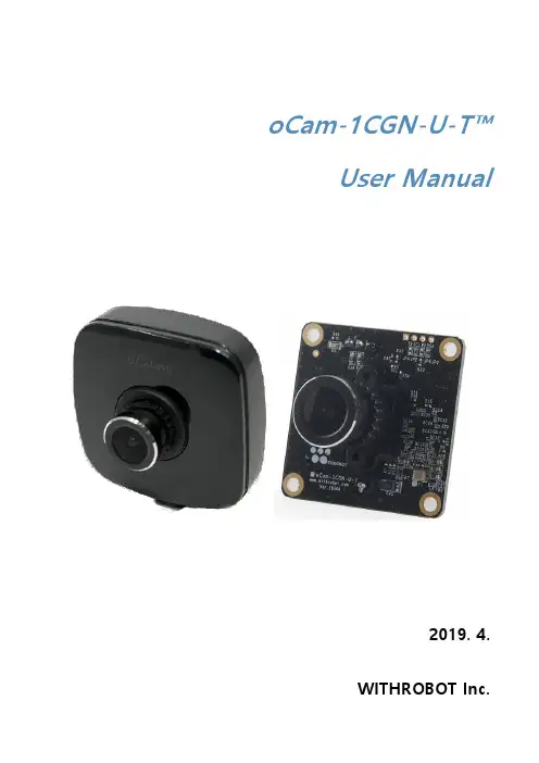
oCam-1CGN-U-T™User Manual2019. 4.WITHROBOT Inc.Revision HistoryNoteThis product is for indoor use only. Severe electrostatic stress can damage the product.Revision History 1 1. INTRODUCTION (3)Features 3 External View 4 Additional Technical Information 5 2. SPECIFICATIONS (6)Camera Specifications 6 Board Dimensions 7 Case Dimensions 7 3. TRIGGER SIGNAL (8)Trigger Signal Connector Specifications 8 Trigger Signal Specifications 9 4. HOW TO USE ON WINDOWS SYSTEM (11)Connection to Windows PC 11 Viewing the Camera Image 12 4. HOW TO USE ON LINUX SYSTEM (14)Connection to Linux PC 14 Viewing the Camera Image 145. NOTES (18)6. TRIGGER SIGNAL BOARD (19)APPENDIX (21)Specifications of the Bundle M12Lens 21 Specifications of the Onboard M12 Lens Holder 22 How to Update the Camera Firmware 23FeaturesoCam-1CGN-U-T is a 1 mega pixels global shutter external trigger color camera with the following features.∙External Trigger: It accepts wide range of external trigger signal from 3V to 24V DC to control precise timing of image acquisition and to be synchronized with external lights and even with other cameras.∙Interface: USB3.0 SuperSpeed∙High Speed: Up to 54 fps @1280 x 960, 180 fps @640 x 480∙Easy Installation: With UVC 1.1 support, no additional driver needs to be installed for Windows and Linux.∙Versatility: Supports wide range of standard M12 lenses with a lens replaceable structure.∙Global Shutter: The electronic global shutter image sensor provides sharp images without image skew.External ViewFigure 1. External view of oCam-1CGN-U-TFigure 2. oCam-1CGN-U-T boardProtective CaseReplaceable M12 LensLens Lock RingMounting Holefor TripodExternal Trigger ConnectorUSB 3.0 ConnectorAdditional Technical InformationFurther technical information including the latest firmware and example source codes are available at “https:///withrobot/oCam/tree/master/Products/oCam-1CGN-U-T”.Figure 3. Technical information siteCamera SpecificationsTable 1. Camera specificationsBoard DimensionsFigure 4. Board size (Unit: mm)Case Dimensions494949*Figure 5. Case size (Unit: mm)* 51mm with tripod mounting adapterTrigger Signal Connector SpecificationsThe oCam-1CGN-U-T accepts a external trigger signal through the 3-pin connector on the back side of the camera. The pin descriptions are as follows: ∙ Pin 1: Signal ground∙ Pin 2: For trigger signals in the range of 3V ~ 5V DC ∙ Pint 3: For trigger signals in the range of 5V ~ 24V DCFigure 6. Pin description of the external trigger input signal connectorThe circuit diagram of external trigger input is shown in the next figure. The input pins and the internal circuit are isolated with a photo coupler. Therefore, the external input trigger signal needs to supply more than 2 mA current to activate properly the trigger.GNDInput pin for Trigger Signal (3V ~ 5V)Input pin forTrigger Signal (5V ~ 24V)Figure 7. Trigger input circuitTrigger Signal SpecificationsThe camera acquires image at the falling edge of the trigger signal. Depending on the trigger signal, the camera operates in one of the 3 modes described as follows.One Shot ModeWith this mode, the camera acquires one frame of image. The trigger signal should maintain the low level at least 1 msec(T1).Figure 8. One shot modeMulti Shot ModeWith this mode, the camera acquires multiple frames of images. The interval between the two adjacent trigger pulses should be at least 2 msec (T2). To get images as specified by the trigger signal frequency, it is needed to set the camera speed at least twice the trigger signal frequency. If the camera speed is set below this, the trigger signal will be applied while the previously acquired image frame is being transmitted. For example, to apply 30 Hz trigger signal, the camera should be set at least 60 fps.Figure 9. Multi shot modeContinuous ModeWith this mode, the camera acquires images continuously at the interval set as camera speed. For example, in the following figure, the camera starts to acquire the image after the trigger signal goes low and acquires the images at the interval of T3 set as the camera fps. When the trigger signal goes high, the camera stops to acquire the images.Figure 10. Continuous modeConnection to Windows PCConnect the USB cable, either USB 2.0 or USB 3.0, to the USB port of the computer. After the camera is detected, the computer will show a message that the camera is connected. To check if the camera is connected successfully, open the device manager and check if the oCam-1CGN-U-T appears correctly as shown below.Figure 11. Connection check (example of Windows 10)Viewing the Camera Image∙As the oCam-1CGN-U-T sends the image in Bayer RGB format, other than the typical YUV format, you need to use image viewing software that can handle this format, such as the oCamViewer program provided by the WITHROBOT Inc.∙On starting the oCamViewer, the main window will appear as shown below.Figure 12. Main window of the oCamViewer for Windows ∙Select the resolution and the fps on the dropdown list.Figure 13. Resolution selection on the oCamViewer∙Click the [Play] button.∙To change the resolution/fps, click the [Stop] button first and then select one on the dropdown list, and then click the [Play] button.∙To check or change the camera parameters, click the [Cam Ctrl] button while the camera is being displayed to open the control window. Use the slide bar to change a parameter.Figure 14. Control window of the oCamViewer for Windows∙To stop viewing the camera image, click the [Stop] button on the main window.∙To terminate the oCamViewer, click the [Exit] button on the main window.∙Full source code of the oCamViewer is available at the following site:https:///withrobot/oCam/tree/master/SoftwareConnection to Linux PCViewing the Camera Image(1) Viewing the Camera Image with the oCamViewer∙As the oCam-1CGN-U-T sends the image in Bayer RGB format, other than the typical YUV format, you need to use image viewing software that can handle this format, such as the oCamViewer program provided by the WITHROBOT Inc.∙On starting the oCamViewer, the main window will appear as shown below.Figure 15. Main window of the oCamViewer for Linux ∙Select the oCam-1CGN-U-T in the “Device” list. On clicking the [Connect] button, the camera image will appear.To change the resolution/fps, select “Format” on the right panel and select one on the dropdown list, and then click the [Apply] button at the bottom.Figure 16. Resolution selection on the oCamViewerTo change the camera parameters, select “Controls” on the right panel and use the slide bar to change a parameter.Figure 17. Camera controls of the oCamViewer for Linux(2) Viewing the Camera Image with the Guvcview∙Start the Guvcview by entering the “guvcview” command on the terminal window.Figure 18. Starting the GuvcviewFigure 19. Guvcview image window∙On the Guvcview camera image window, the current frame rate is shown on the top bar.On the oCam-1CGN-U-T, you can adjust the focus by rotating the lens by hand. Therefore, in a vibrating environment, the lens can be loosened by being rotated by itself. To prevent this, it is recommended to lock the lens by using the supplied lens lock ring after you finish adjusting the focus.To change the lens, you need to loosen the lock ring first before you take out the lens from the holder.The oCam-1CGN-U-T can be used with any signal source as long as it meets the input signal specification. It is recommended to use the mTrigger, however, which is a trigger signal board supplied by the WITHROBOT Inc. for full compatibility and verified operation.The mTrigger signal board supports the following 4 signal modes which are all user programmable to set the detailed signal parameters.Table 2. Trigger modesMultiple mTrigger boards can be connected in a cascade configuration to provide unlimited number of trigger signals.The following is the major specifications of the mTrigger signal board.Table 3. mTrigger specificationsSpecifications of the Bundle M12LensSpecifications of the Onboard M12 Lens HolderHow to Update the Camera Firmware∙The latest camera firmware is available at the following site.https:///withrobot/oCam/tree/master/Firmware ∙The firmware update software (UpdateFW.exe) is available at the following site.https:///withrobot/oCam/tree/master/Firmware/Update_FW ∙The instruction to use the UpdateFW.exe is available at the following site.https:///withrobot/oCamS/tree/master/Firmware ∙The oCamViewer source code is available at the following site.https:///withrobot/oCam/tree/master/Software Technical Support∙E-Mail:***********************Copyright(c) 2019 WITHROBOT Inc. All rights reserved.。
抓拍摄像机的使用方法
嘿,朋友们!今天咱来讲讲抓拍摄像机的使用方法。
首先呢,你得把抓拍摄像机找个合适的地儿放好呀。
这地方可得好好挑,要能清楚拍到你想拍的东西。
然后呢,就是各种设置啦。
比如说清晰度啊,这个可得调好,不然拍出来模模糊糊的可不行。
还有那个拍摄的间隔时间,根据你的需要来设置哦。
再来说说角度问题。
角度很关键啊,得让它能把该拍的都拍到,不能有遗漏。
这就需要你多试试,找到那个最佳角度。
还有哦,别忘了检查内存够不够。
要是拍着拍着没内存了,那不就白瞎啦。
总之呢,用抓拍摄像机得细心点,把该注意的都注意到,这样才能拍出好的效果。
我的观点就是,只要用心去了解和使用抓拍摄像机,就能让它发挥大作用!。
VintenCamera Control SolutionsO p e r a t o r s G u i deVector 450Pan & Tilt HeadVision 450Pan and Tilt HeadPublication Part No. 3805-8Issue 1Copyright © Vinten Broadcast Limited 2004All rights reserved throughout the world. No part of this document may be stored in a retrieval system, transmitted, copied or reproduced in any way including, but not limited to, photocopy, photograph, magnetic or other record without the prioragreement and permission in writing ofVinten Broadcast Limited.Vinten, Vector, QuickFit and Quickfix are registered trademarks of Vinten Broadcast Limited.Safety - read this firstWarning Symbols in this Operators GuideWhere there is a risk of personal injury, injury to others, or damage to the pan Array and tilt head or associated equipment, comments appear, highlighted by theword WARNING! and supported by the warning triangle symbol.Technical dataWeight 15 kg (33 lb) Height to wedge adaptor mounting face24.8 cm (11.3 in.) Length22.5 cm (8.9 in.) Width34.2 cm (13.5 in.) Typical payload10-45 kg (22-99 lb) - See balance graph Tilt range±90°Pan range 360°Operating temperature range - 40°C to + 60°C (- 40°F to + 140°F) Pedestal/tripod fixing150 mm ball baseorFour-hole flat base with `Quickfix' mountingand provision for Mitchell adaptorFurther informationFor further information or advice regarding this pan and tilt head, please contact Vinten Broadcast Limited, your local Vinten distributor (see back cover) or visit our website.For details on maintenance and spare parts, please refer to the Vector 450 Pan and Tilt Head Maintenance Manual and Illustrated Parts List (Publication Part No. 3805-9) This is obtainable from Vinten Broadcast Limited or your local Vinten distributor. For information on-line, visit ourwebsite at.3ContentsPage Safety - read this first. . . . . . . . . . . . . . . . . . . . . . . . . . . . . . . . . . . . . . . . . . . . . . . . . . . . . . . . 3 Technical data. . . . . . . . . . . . . . . . . . . . . . . . . . . . . . . . . . . . . . . . . . . . . . . . . . . . . . . . . . . . . . 3 Further information. . . . . . . . . . . . . . . . . . . . . . . . . . . . . . . . . . . . . . . . . . . . . . . . . . . . . . . . . . 3 Introduction. . . . . . . . . . . . . . . . . . . . . . . . . . . . . . . . . . . . . . . . . . . . . . . . . . . . . . . . . . . . . . . . 8 OperationInstalling the head . . . . . . . . . . . . . . . . . . . . . . . . . . . . . . . . . . . . . . . . . . . . . . . . . . . . . . . . 11 Pan bars. . . . . . . . . . . . . . . . . . . . . . . . . . . . . . . . . . . . . . . . . . . . . . . . . . . . . . . . . . . . . . . . 11 Fitting a camera. . . . . . . . . . . . . . . . . . . . . . . . . . . . . . . . . . . . . . . . . . . . . . . . . . . . . . . . . . 11 Balancing the head . . . . . . . . . . . . . . . . . . . . . . . . . . . . . . . . . . . . . . . . . . . . . . . . . . . . . . . 12 Locking the platform . . . . . . . . . . . . . . . . . . . . . . . . . . . . . . . . . . . . . . . . . . . . . . . . . . . . . . 13 Pan and tilt brakes. . . . . . . . . . . . . . . . . . . . . . . . . . . . . . . . . . . . . . . . . . . . . . . . . . . . . . . . 14 Pan and tilt drag. . . . . . . . . . . . . . . . . . . . . . . . . . . . . . . . . . . . . . . . . . . . . . . . . . . . . . . . . . 14 Digital display. . . . . . . . . . . . . . . . . . . . . . . . . . . . . . . . . . . . . . . . . . . . . . . . . . . . . . . . . . . . 15 ServicingGeneral . . . . . . . . . . . . . . . . . . . . . . . . . . . . . . . . . . . . . . . . . . . . . . . . . . . . . . . . . . . . . . . . 17 Routine maintenance. . . . . . . . . . . . . . . . . . . . . . . . . . . . . . . . . . . . . . . . . . . . . . . . . . . . . . 17 Cleaning. . . . . . . . . . . . . . . . . . . . . . . . . . . . . . . . . . . . . . . . . . . . . . . . . . . . . . . . . . . . . . . . 17 Electronic unit battery replacement. . . . . . . . . . . . . . . . . . . . . . . . . . . . . . . . . . . . . . . . . . . 18 Balance mechanism digital display calibration. . . . . . . . . . . . . . . . . . . . . . . . . . . . . . . . . . . 19 Converting the base. . . . . . . . . . . . . . . . . . . . . . . . . . . . . . . . . . . . . . . . . . . . . . . . . . . . . . . 20 Adjustments. . . . . . . . . . . . . . . . . . . . . . . . . . . . . . . . . . . . . . . . . . . . . . . . . . . . . . . . . . . . . 21 Parts List . . . . . . . . . . . . . . . . . . . . . . . . . . . . . . . . . . . . . . . . . . . . . . . . . . . . . . . . . . . . . . . . . 23Associated publicationVector 450 Pan and Tilt HeadMaintenance ManualPublication Part No. 3805-94Vision 450 (Right-Hand Side, with Spherical Base)(1)Camera wedge(2)EFP Quickfit adaptor(3)Quickfit adaptor safety lock plate(4)Quickfit adaptor lock bar(5)Sliding plate adjustment handle(6)Carrying handle(7)Centre lock plunger(8)Balance knob(9)Tilt brake lever(10)Pan brake lever(11)Bowl clamp5(12)150 mm spherical base(13)Illuminated level bubble(14)Timer button(15)Digital display(16)Illumination button(17)Centre lock release lever(18)Quickfit adaptor mounting screws(19)Camera fixing screws6Vision 450 (Left-Hand Side, with Flat Base)(20)Sliding plate clamp lever(21)Pan bar mounting(22)Tilt drag adjustment knob(23)Pan drag adjustment knob(24)Mitchell adaptor key way(25)Four-hole mounting plate(26)Battery cover(27)Graduated sliding plate78IntroductionThe Vector 450 pan and tilt head embodies a unique and patented spring counterbalancing mech-anism, thin film (TF) drag assemblies for pan and tilt motions and an adjustable camera mounting plate.Perfect balanceThe spring counterbalancing mechanism comprises four springs operating against a three-dimen-sional cam connected to the camera mounting platform. The balance mechanism is adjusted by a knob (8), situated on the right front lower part of the main body, which varies the mechanical advantage between the cam and the springs. The knob has a ‘push in and turn’ action and is fitted with a clutch to prevent inadvertent damage to the balance mechanism.Maximum and minimum payloads that can be balanced, and tilt ranges, are dependent on the weight of the camera and accessories and on the centre of gravity (C of G) height.The graph shows the range of load and C of G height that can be maintained in balance. The shad-ed area of graph corresponds to those load/C of G combinations that can be balanced over the full tilt range. The area to the right indicate the progressively reducing tilt range with greater load and higher C of G.Balance graph00204060802040608010012014016018050751001251501752002345678mm in.kg lbC e n t r e o f G r a v i t y H e i g h tTotal Payload±90°Where a load/C of G combination falls outside of the graph it will be necessary to increase or de-crease the weight or the C of G height - if possible - to enable the head to balance the load.A digital display (15) indicates the setting of the balance mechanism on a scale of 0-100. The dis-play is active when the balance knob (8) is turned and extinguishes automatically approximately 15 seconds after adjustments are complete. The display may be lit by pressing the illumination button (16). The battery for the system is housed in a compartment in the base of the head, closed by a cover (25).TF dragBoth the pan and tilt mechanisms incorporate the Vinten thin film (TF) system to ensure smooth movement of the camera about these axes and are fitted with control knobs (22)(23) to adjust the drag setting. The whip-pan facility is unaffected by the pan drag setting. Both drag knobs are pro-vided with scales illuminated by the button (16). The lights will go out after approximately 15 sec-onds.Pan and tilt brakesFriction brakes on each axis allow the head to be locked at any chosen position. The operating levers for both brakes (9)(10) are located side-by-side on the right-hand side of the head. Centre lockA centre lock (7) allows the head to be locked in the horizontal position.Illuminated level bubbleA level bubble (13), illuminated by pressing the illumination button (16), is fitted to the rear of the head. The same button also illuminates the pan and tilt drag knob scales and the LCD display. The light will go out after approximately 15 seconds.Pan barPan bar mounting points (21) are located at the rear of the head, on either side of the camera mounting platform. A telescopic pan bar is supplied and is attached using a pan bar clamp, with angular adjustment available on the mount serrations. A second pan bar may be fitted.EFP Quickfit adaptorThe camera is attached to the head by means of a EFP Quickfit adaptor (2), which is mounted on a graduated sliding plate (27). The position of the slide plate is adjusted by a retractable knob (5) and a clamp (20) is provided to hold the slide plate in position.Tripod/pedestal mountingThe Vector 450 pan and tilt head is available with either a 150 mm ball base or a flat base. The two base assemblies are interchangeable (See Converting the base on page20).Adaptors are available which enable the heads to be installed on tripods or pedestals fitted with other mountings. These are listed in the Parts List under Optional accessories.150 mm ball baseThe 150 mm ball base is designed for installation on a compatible Vinten tripod.9Flat baseThe flat base is has a standard Vinten four-hole mounting plate (25), which includes a `Quickfix' mounting and provision for a Mitchell adaptor (24).Carrying handleA retractable carrying handle (6) is provided on the right-hand side of the head. The handle is spring-loaded to the closed position.Electronic unitAn electronic unit is fitted to the rear of the head, powered by a battery housed in a compartment (26) in the base of the head. The unit comprises a two-row digital display (15) and two push-button buttons - an illumination button (16), which illuminates the LCD display, levelling bubble and the pan and tilt drag knob scales for 15 seconds, and a timer button (14). Pressed singly or in con-junction with each other, the buttons provide control of the time, stopwatch and calibration func-tions.For a detailed description of each function, see Digital display on page15.1011OperationInstalling the headTo install a head with a ball mount, remove the bowl clamp assembly (11) from the head, position the head on the tripod and refit the bowl clamp assembly from below. Level the head with the aid of the level bubble (13) and tighten the bowl clamp. The level bubble may be illuminated by press-ing the switch (16). The light will go out after approximately 15 seconds.The flat base head may be installed on a standard ‘Vinten’ tripod or pedestal using the four mount-ing bolts and washers provided or by using a `Quickfix' adaptor. A Mitchell adaptor may also be used.After mounting the head on a tripod, use the level bubble (13) to set it level. The level bubble may be illuminated by pressing the illumination button (16). The light will go out after approximately 15 seconds.Pan barsFit the pan bars on the mountings (21) and adjust the position of each one before tightening the clamps. Adjust the length of the telescopic pan bar. Optional fixed and short fixed pan bars are available (see Main assemblies in the Parts List).Fitting a cameraThe camera is attached to the head by means of a EFP Quickfit adaptor. To fit a camera, proceed as follows:Free the camera wedge (1) from the EFP Quickfit adaptor by sliding the safety lock plate (3) fully forward and pushing in the lock bar (4).Attach the wedge (1) to the camera/lens using the camera fixing screws (19).WARNING!If using lifting equipment to raise or lower the head, use slings or straps. DO NOT use shackles.Ensure that slings or straps are securely attached to the head. A suitable lifting point is at the rear of the platform, accessed by moving the sliding plate (27) to the fully forward position.DO NOT attach lifting slings or straps to the carrying handle.WARNING!Before installing the head, hold a fixing bolt in position and check that the threaded end does not project more than 12mm(15/32 in.) above the mounting faceWARNING!Do not rely on the tilt brake when changing the payload. Always engage the centre lock. Ensure that the weight and C of G height of the total payload is within the range for which the head is designed If installing on a pedestal, lock the pedestal in the fully depressed position before installing the camera.12Ensure that the centre lock (7) is engaged (see Locking the platform on page 13).Insert the forward edge of the camera wedge (1) into the Quickfit adaptor. Push the wedge down until the lock bar (4) clicks out.Slide the safety lock plate (3) backwards to hold the lock bar (4) in position.Install the remainder of the payload (lens, zoom and focus controls, viewfinder, prompter etc).Balancing the headBalancing the Vector 450 head achieves two objectives. Firstly, when a head is correctly balanced the operator will need a minimum amount of even effort to move the head. Secondly, once bal-anced, the head and its payload can be set to any tilt position and the head will maintain this po-sition with ‘hands off’.The graph shows the range of load and C of G height that can be maintained in balance. The shad-ed area of graph corresponds to those load/C of G combinations that can be balanced over the full tilt range. The area to the right indicate the progressively reducing tilt range with greater load and higher C of G.Fore and aft balanceWhen positioning the payload it is important to be aware of the potential danger of an unbalanced payload falling away suddenly. Before disengaging the centre lock, push in and turn the balance adjustment knob (8) to its mid point setting (50 on the digital display). Depending on the payload weight, it may be necessary to increase or decrease this setting to enable the payload to be cor-rectly balanced fore and aft.Balance the payload fore and aft as follows:Ensure that the centre lock is engaged (see “Locking the platform” on page 13) and that the camera and all accessories are fitted.Turn the tilt drag adjustment knob (22) to its minimum setting.Push in and turn the balance adjustment knob (8) to its mid point setting.Holding the pan bar to steady the platform, disengage the centre lock (see “Locking the plat-form” on page 13).NOTE: It is important that the pan bar(s) and all camera accessories (lens, zoom and focus controls, viewfinder, prompter etc.) are fitted in their operational position before balancing the head. Any equipment fitted or adjusted later willunbalance the head.WARNING!Be prepared to prevent the head falling away suddenly. In the event of the head falling away violently, increase the setting on the balance adjustment knob (8).13Release the sliding plate clamp (20) and pull out the sliding plate adjustment knob (5) until it engages with the platform drive. Turn the knob to move the sliding plate fore and aft to achieve horizontal balance.The horizontal balance is correct when no perceptible tilting force can be felt on the pan bar with the platform level. Apply the sliding plate clamp (20) and push in the adjustment knob (5) to its stowed position.If there is insufficient movement in the sliding plate to achieve balance, reposition the Quickfit adaptor (see Repositioning the EFP Quickfit adaptor on page 21), refit the load and repeat the horizontal balancing procedure.The sliding plate is graduated. Make a note of the position to facilitate rebalancing this par-ticular payload.Payload weight and C of G height adjustmentWhen fore and aft balance has been achieved, carry out the payload weight and C of G height adjustment as follows:Using the pan bar, tilt the platform forward and backward. When correctly balanced, there should be no perceptible tilting force on the pan bar at any angle of tilt and the head should remain in any tilt position to which it is set.If the head tends to fall away when the platform is tilted, set the platform level and push in and turn the balance adjustment knob (8) clockwise to increase the balance setting. If the head tends to spring back to centre, set the platform level and push in and turn the balance adjustment knob (8) counter-clockwise to decrease the balance setting.When the payload weight and C of G height adjustment is complete, check that the fore and aft balance remains satisfactory. Re-adjust the position of the sliding plate if necessary. The digital display (15) will display the balance setting while balance is being adjusted. Make a note of the final setting to facilitate rebalancing this particular payload.After balancing, exercise the head through both axes to confirm that it operates smoothly. Locking the platformThe centre lock mechanism is operated by a plunger on the right-hand side of the head. To en-gage the lock, hold the platform in the horizontal position and push the plunger (7) inwards until it latches and the release lever (17) appears. Use the pan bar to rock the platform slightly whilst pushing the button.To release the centre lock, rock the platform slightly and push down on the release lever (17).NOTE:The sliding plate is graduated to facilitate balancing. If the balance setting of the payload is known, turn the knob until that setting is reached.NOTE:If the digital balance setting of the payload is known, push in and turn the balance knob (8) until the digital display (15) shows that setting.NOTE:Setting the platform level will facilitate adjusting the balance settingPan and tilt brakesThe pan (10) and tilt brakes (9) are operated by levers on the right of the head. The brakes are applied by pushing the appropriate lever down and released by pulling the lever up.The brakes should be applied whenever the camera is left unattended.Pan and tilt dragBoth the pan and tilt mechanisms incorporate the Vinten thin film (TF) system to ensure smooth movement of the camera about these axes and are fitted with control knobs to adjust the drag set-ting.Both drag knobs are provided with illuminated scales, graduated from 0 to 9. To illuminate the scales, press the button (16). The light will go out after approximately 15 seconds.The drag adjustment knobs are mounted on the left-hand side of the head. The smaller pan drag knob (23) is on the front lower part of the main body, with the larger tilt drag knob (22) in the centre on the tilt drag housing.To increase drag, turn the knob clockwise, towards a higher graduation. To decrease drag, turn the knob anti-clockwise, towards a lower graduation.The whip-pan facility is unaffected by the pan drag setting.14Digital displayThe digital display (15) comprises a two-row LCD display. It has three modes of operation, select-ed by the buttons (14)(16). The display may be illuminated by pressing the illumination button (16). Clock and stopwatchThe top row of the display is a 24-hour clock (15.1), which is always visible. This is the default mode. The bottom row is a stopwatch, counting in seconds and minutes from 00:00 to 59:59.To set the clock:Press both buttons (14)(16) momentarily. The hours display will flash.Use the timer button (14) to increment the hours.Press the illumination button (16). The minutes display will flash.Use the timer button (14) to increment the minutes.Press the illumination button (16) to exit and start the clock.To display, start, stop or clear the stopwatch:Momentarily pressing the timer button (14) will display, start, stop or clear the stopwatch in that sequence.BalanceBalance mode is active any time the balance adjustment knob (8) is turned (unless the stopwatch is running) and remains active for 15 seconds after adjustment has finished. In this mode the bot-tom row shows the setting of the balance mechanism on a scale of 0.0 to 100.0 The BAL legend (15.3) is also lit. The top row of the display shows the 24-hour clock.Digital display15CalibrationThis mode allows the balance display to be calibrated (see Balance mechanism digital display calibration on page19). It is activated by pressing and holding both buttons (14)(16) for five sec-onds.Low batteryThe low battery indicator (15.2) will flash whenever the battery requires replacement (see Elec-tronic unit battery replacement on page18).1617ServicingGeneralThe Vector 450 pan and tilt head is robustly made to high engineering standards and little attention is required to maintain serviceability save regular cleaning.Refer to the appropriate section in the Maintenance Manual if any defect is apparent. Adjustments and repairs should be carried out only by a competent person.Routine maintenanceReplace the electronic unit battery whenever the low battery indicator flashes.During use, check the following:Check the effectiveness of the pan and tilt brakes. Reset as necessary.Check the effectiveness of the slide plate clamp. Reset as necessary.Check the operation of the balance mechanism digital display and the illumination of the LCD, level bubble and drag knobs. Replace battery if necessary.No further routine maintenance is required.CleaningDuring normal use the only cleaning required should be a regular wipe over with a lint-free cloth. Dirt accumulated during storage or periods of disuse may be removed with a semi-stiff brush. Par-ticular attention should be paid to the wedge location faces of the wedge adaptor.Use out-of-doors under adverse conditions may require special attention and the head should be covered when not in use. Salt spray should be washed off using fresh water at the earliest oppor-tunity. Sand and dirt act as an abrasive and should be removed using a semi-stiff brush or a vac-uum cleaner.NOTE:Use only detergent-based cleaners. DO NOT use solvent- or oil-based cleaners, abrasives or wire brushes to remove accumulations of dirt as these damage the protective surfaces18Electronic unit battery replacementThe battery powers the digital display and illuminates the LCD, the level bubble and the drag knob scales.The battery should be replaced whenever the low battery indicator flashes.Prise out the battery cover (26).Pull the battery (26.1) out of the battery compartment as far as the wiring will allow.Pull the connector (26.2) off the terminals of the old battery and push it onto the terminals of the new battery (26.1).Install the battery (26.1) in the battery compartment, ensuring that the wiring is neatly stowed.Refit the battery cover (26).Press the illumination button (16) and ensure that the balance mechanism digital display (15), the level bubble (13) and drag knob scales (22)(23) are lit for approximately 15 sec-onds.Turn the balance knob (8) and ensure that the balance display (15) is active for approxi-mately 15 seconds.Reset the clock (see Clock and stopwatch on page 15).NOTE:Removal of the battery will not affect the calibration of the balance mechanism display.Battery replacement19Balance mechanism digital display calibrationThe digital display (15) indicates the setting of the balance mechanism on a scale of 0 (minimum setting) to 100 (maximum setting). In the unlikely event of this system requiring calibration, pro-ceed as follows:Level the platform and apply centre lock (7).Press and hold both buttons (14)(16) until CAL is displayed on the top row of the display. Push in and turn the balance knob (8) counterclockwise until its minimum end stop is reached, then turn back two full turns. The bottom row of the display will flash 0.Press and release the timer button (14). The bottom row of the display will flash 100.Push in and turn the balance knob (8) clockwise until its maximum end stop is reached, then turn back two full turns.Press and release the timer button (14). Calibration is now complete and the display will revert to the default clock mode.After calibration, rebalance the head (see “Balancing the head” on page 12).NOTE: If more than five minutes is allowed to elapse before completion, the system will shut down and revert to its previous settings.Balance mechanism digital display calibrationConverting the baseSpares kits are available to convert the head from ball base to flat base versions and vice versa.Kit 3805-900SP comprises a ball base, bowl clamp and fixing hardware; while kit 3805-901SP has a flat base, mounting bolts and washers, a spanner and fixing hardware.To change the base:Remove the payload, then remove the head from its mounting.On the base, remove eight screws (12.1) and separate the base (12) from the head.Position the replacement base on the head and secure with eight screws (12.1), using Loc-tite 222E.Converting the base2021AdjustmentsTo enable the payload to be correctly balanced, the EFP Quickfix adaptor may require reposition-ing.The following adjustments may be necessary after prolonged use:The platform slide clamp may require adjustment. The pan and tilt brakes may require adjustment.Repositioning the EFP Quickfit adaptorThe EFP Quickfit adaptor (2) is secured by six screws (18) which pass through the adaptor into the sliding plate (27). The EFP Quickfit adaptor may be fitted in three positions.To reposition the EFP Quickfit adaptor:Engage the centre lock (see Locking the platform on page 13) and remove the payload.Hold the body of the EFP Quickfit adaptor (2) and remove the six securing screws (18).Reposition the Quickfit adaptor (2) on the sliding plate (27), ensuring that the lock bar (4) is towards the rear.Insert the six screws (18)in the holes in the adaptor and tighten.WARNING!Overlong screws will prevent the sliding plate from operating.Always use the screws provided (M4 x 12 mm).Platform slide clamp adjustmentPlatform slide clamp adjustmentThe platform slide clamp should be set so that, in the up or clamped position it prevents the plat-form slide from being moved, while in the down or released position it allows free adjustment of the slide. To adjust the clamp, proceed as follows:Pull the slide clamp lever (20) fully upwards.Slacken the clamp screw (20.2).Turn the slotted shaft (20.1) fully clockwise to apply the clamp.Tighten the clamp screw (20.2).Move the lever (20) over its full range and ensure that, in the clamped position, it prevents the slide from being moved, while in the released position it allows free adjustment of the slide. Re-adjust if necessary.Pan and tilt brake adjustmentThe pan (10) and tilt brakes (9) are operated by levers on the right of the head. The brakes are applied by pushing the appropriate lever down and released by pulling the lever up.If the brakes become ineffective, adjustment should be carried out by qualified personnel in ac-cordance with the Maintenance Manual (Publication Part No. 3805-9).22Parts ListThe following list includes the main assemblies, user-replaceable spare parts and optional acces-sories. For further information regarding repair or spare parts, please contact Vinten Broadcast Limited or your local distributor.For information on-line, visit our website atMain assembliesVector 450 pan and tilt head - flat base3805-3F Vector 450 pan and tilt head - spherical base3805-3S EFP Quickfit adaptor3761-3 Standard wedge plate3761-13 Telescopic pan bar and clamp3219-82 Fixed pan bar and clamp3219-94 Short fixed pan bar and clamp3219-93 Fixing bolt L054-714 Washer - for fixing bolt L602-122 Spanner - for fixing bolts J551-001 User-replaceable spare partsBattery - 9V, 6LR61 (PP3, 6AM6, MN1604, E-BLOCK or equivalent)C550-023 Optional accessoriesSpherical base adaptor kit3805-900SP Flat base adaptor kit3805-901SP Heavy-duty Quickfix adaptor3490-3 Levelling adaptor Quickfix to 4-bolt flat base3328-30 Lightweight Mitchell adaptor3103-3 Heavy-duty Mitchell adaptor -for Vinten pedestal mounting in conjunction with Hi-hat adaptor Part No. 3055-33724-323。
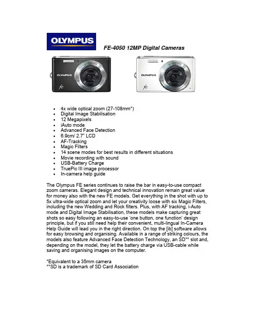
FE-4050 12MP Digital Cameras∙4x wide optical zoom (27-108mm*)∙Digital Image Stabilisation∙12 Megapixels∙iAuto mode∙Advanced Face Detection∙ 6.9cm/ 2.7" LCD∙AF-Tracking∙Magic Filters∙14 scene modes for best results in different situations∙Movie recording with sound∙USB-Battery Charge∙TruePic III image processor∙In-camera help guideThe Olympus FE series continues to raise the bar in easy-to-use compact zoom cameras. Elegant design and technical innovation remain great value for money also with the new FE models. Get everything in the shot with up to 5x ultra-wide optical zoom and let your creativity loose with six Magic Filters, including the new Wedding and Rock filters. Plus, with AF tracking, i-Auto mode and Digital Image Stabilisation, these models make capturing great shots so easy following an easy-to-use ‘one button, one function’ design principle, but if you still need help their convenient, multi-lingual In-Camera Help Guide will lead you in the right direction. On top the [ib] software allows for easy browsing and organising. Available in a range of striking colours, the models also feature Advanced Face Detection Technology, an SD** slot and, depending on the model, they let the battery charge via USB-cable while saving and organising images on the computer.*Equivalent to a 35mm camera**SD is a trademark of SD Card AssociationSpecificationsImage SensorEffective pixels12 MegapixelsFilter array Primary colour filter (RGB)Full resolution12.2 MegapixelsType1/2.3 '' CCD sensorLensOptical zoom 4 x (WIDE)Focal length 4.9 -19.6 mmFocal length(equiv. 35mm)27 -108 mmMaximumaperture3.2 -5.9Structure 6 lenses / 5 groupsAspherical glasselements3Digital ZoomEnlargementfactor4 x / 16 x combined with optical zoomLCDResolution230000 dotsMonitor size 6.9 cm / 2.7 ''LCD type TFTFrame assistance YesBrightnessadjustment2 levelsFocusing SystemModes iESP, Face Detection AF, Spot, AF Tracking Method TTL iESP auto focus with contrast detection Standard mode0.6m -∞ (wide) / 1.0m -∞ (tele)Makro mode0.2m -∞ (wide) / 0.4m -∞ (tele)Super MacromodeClosest focusing distance: 8 cm Light MeteringModes ESP light meteringExposure SystemShutter speed1/4 -1/2000 s / < 4 s (Night scene)Enhancement function Digital Image Stabilisation Plus Advanced Face Detection TechnologyExposurecompensation+/-2 EV / 1/3 stepsModes i-Auto, Programme automatic, DIS mode, Scene Modes, Magic Filter, Panorama, MovieScene Modes Number of scene modes14Modes Portrait, Landscape, Night Scene, Night Scene with portrait, Sports, Indoor, Candle, Self-portrait, Sunset, Fireworks, Cuisine, Documents, Beach and Snow, PetMagic FilterTypes Pop Art, Pin Hole, Fisheye, Drawing, Soft Focus, Punk SensitivityAuto AUTOManual ISO 64, 100, 200, 400, 800, 1600White BalanceAUTO WB system YesPreset values Overcast, Sunlight, Tungsten, Flourescent 1, Flourescent 2, Flourescent 3Internal FlashModes AUTO, Red-eye reduction, Fill-in, Off Working range(wide)0.2 -4.2 m (ISO 800)Working range(tele)0.4 -2.3 m (ISO 800)Image ProcessingEngine TruePic IIIPixel mapping YesNoise reduction YesShadingcompensationYesDistortioncompensationYesFunctionProcessingPanorama YesImage EditingResize YesTrimming YesRed-eye reduction YesShadowAdjustmentYesView ImagesModes Single, Index, Zoom, Slide showIndex4x3 / 6x5 framesZoom 1.1 -10 xAuto rotation YesImage protectmodeYesView MovieModes Frame by frame, Fast forward, Reverse playback Still ImageRecordingDCF YesEXIF 2.21PIM IIIDPS PictBridgeDPOF YesMovie RecordingSystemRecording format AVI Motion JPEG®Movie quality640 x 480 / 30 fps Recording time: no limitImage Stabilisation Mode Digital Image Stabilisation Note: maximum file size 2GBSound RecordingSystemVoice playback YesSound recording Yes , format: WAV Speaker NoMemoryInternal memory92 MB Removable Media SD / SDHCImage Size12M3968 x 29768M3264x 24485M2560 x 19203M2048 x 15362M1600 x 12001M1280 x 960VGA640 x 48016:91920 x 1080MenuMenu languagesin camera39Other FeaturesPerfect ShotYesPreviewMenu guide YesSelf timer 2 / 12 sPower SupplyBattery LI-42B Lithium-Ion BatteryInternal Charging YesInterfaceDC input NoCombined A/V &YesUSB outputUSB 2.0 HighYesSpeedSizeDimensions (W x91.7 x 56.0 x 19.9 mmH x D)Weight112 g (including battery and memory card)。

郑州吉瑞特电子科技有限公司快速操作手册<V1.01> ◎吉瑞特电子.版权所有User Manal编写人:吴楠Version:V1.01审批人: Date:2014/3/19版本变更记录日期版本作者/修改者描述审核人2014/3/14 V1.0 吴楠创建2014/3/19 V1.01 吴楠添加WIFI快速操作项目录1. 接口简介 (4)2. 设备连接 (5)3. 局域网内IE观看 (6)4. 客户管理观看 (8)5. 无线(wifi)设置 (10)首先感谢您选购吉瑞特网络摄像机。
本公司研发生产的网络摄像机具有稳定性强,操作简单,功能强大等特点,产品通过CE,FCC及公安部检测认证。
有关产品的详细说明请参阅产品包装盒内配套光盘上的《产品使用说明》。
1. 接口简介(接口一)DC5V:直流电源接口,5V直流电源输入,电源用错会造成摄像机的水久损坏。
I/O Alarm:1:报警输入、输出接口,开关量输入。
常开常闭可以在客户端中配置,默认为常开输入。
2/3:地。
4:报警输出,开关量输出,用于报警时联动输出。
AUDIO:音频,音频线性输出,可外接带功放喇叭进行对讲。
ANT:WIFI或3G产品天线接口。
T/F和USB:可插入TF卡或U盘,做为产品的内置存储。
(接口二)红色:12V直流电源接口,我们建议使用优质的开关电源,12V2A。
黑色:RJ45接口,10/100自适应以太网口,2. 设备连接如图所示,用网线将摄像机连接交换机/路由器/HUB或直接与电脑相连,用电源给设备供电,等待1分钟左右,摄像机启动完成。
电脑要与摄像机通信,首先确认电脑的IP是否与摄像机IP段一致,电脑查看IP方法:1.网上邻居》属性》本地连接》详细信息,如图1所示2.开始》运行,输入“CMD”命令进入命令提示符窗口,输入“ipconfig”+回车即可查看电脑IP。
如图2所示(图1)(图2)3. 局域网内IE观看1. 摄像机内置web服务器,可直接通过IE进行访问,摄像机默认IP为:http://192.168.1.102. 首次IE浏览时需下载并安装控件,通常IE缺省的安全设置禁止用户下载和运行控件,因此要修改IE的安全设置,在IE浏览器菜单栏中找到“工具”-->“Internet选项”进入Internet选项-->安全-->自定义级别在安全设置里把有关ActiveX控件和插件全部启用,确认5. 打开IE浏览器,输入网址:http://192.168.1.10,输入用户名admin,密码为空,登入后即可对摄像机进行观看和管理。
Auto High BeamThe front sensor camera detects the light sources ahead of the vehicle such as the lights of a preceding or oncoming vehicle, or street lights. When you are driving at night, the system automatically switches the headlights between lowbeam and high beam depending on the situation.For the system to work properly:•Do not place an object that reflects light on the dashboard.•Keep the windshield around the camera clean. When cleaning the windshield, be careful not to apply windshield cleanser to the camera lens.•Do not attach an object, sticker or film in the area around the camera.•Do not touch the camera lens.If the camera receives a strong impact or requires repair in the area near the camera, consult a dealer.If the Some Driver Assist Systems Cannot Operate: Camera Temperature Too High message appears:•Use the climate control system to cool down the interior and, if necessary,also use defroster mode with airflow directed toward the camera.•Start driving the vehicle to lower the windshield temperature, which cools down the area around the camera.If the Some Driver Assist Systems Cannot Operate: Clean Front Windshield ,message appears:•Park your vehicle in a safe place, and clean the windshield. If the message does not disappear after you have cleaned the windshield and driven for a while, have your vehicle checked by a dealer.VEHICLE CONTROLSn Automatically switching between high beam and low beamWhen auto high beam is active, the headlights switch between high beam and low beam based on the following conditions.Switching to high beamAll of the following conditions must be met before the high beams turn on.•Your vehicle speed is 25 mph (40 km/h) or more.•There are no preceding or oncoming vehicles with headlights or taillights turned on.•There are few street lights on the road ahead.Switching to low beamOne of the following conditions must be met before the low beams turn on.•Your vehicle speed is 15 mph (24 km/h) or less.•There is a preceding or oncoming vehicle with headlights or taillightsturned on.•There are many street lights on the road ahead.n Manually switching between high beam and low beamIf you want to manually switch the headlights between high beam and low beam, follow either of the procedures below. Note that when you do this, the auto high beam indicator will turn off and the auto high-beam will be deactivated.Using the lever:Pull the lever toward you for flashing the high beams then release it within about one second while driving.To reactivate, pull the lever toward you for flashing the high beams then release it while driving. The auto high beam indicator will come on.Using the light switch:Turn the light switch to .To reactivate, turn the light switch to AUTO when the lever is in the low beam position, the auto high beam indicator will come on.VEHICLE CONTROLS。
VLEBIRCOLOR IR DOME CAMERAR040171B/1v20FRONT VIEW SIDE VIEWFEATURES❑SONY 1/3” Super HAD CCD sensor Color camera.❑Employs Digital Signal Processor (DSP) IC for image control.❑Total pixels of sensor: NTSC=270K/ PAL=320K (EIA=250K/ CCIR=290K) for normal resolution models.❑High sensitivity, low smear, excellent anti-blooming and high S/N ratio.❑Supports functions: Auto Electronic Shutter (AES), Auto Gain Control (AGC), Auto White Balance (AWB), and Back Light Compensation (BLC).❑ Economical solution, Includes Board Lens and furnished with mounting bracket.❑DC type power request, low power consumption.❑Built-in an infrared illuminant to assist for cameras in low illumination environment.❑Long life luminary with using special wavelength Infrared LED.❑Built-in environment illumination detection and control circuit that can turn-on/off the infrared illuminant automatically.SPECIFICATIONS(Note: Design and specifications are subject to change without prior notice.)Image Device 1/3” Color CCD(Sony Chipset) Picture Elements NTSC: 510x492,PAL: 500x582 Resolution 420 TVLMin. Illumination 0.02 LUX / F2.0 (Day)0 Lux (IR ON)S/N Ratio More than 45 dBElectronic Shutter NTSC: 1/60s~1/100,000s, PAL:1/50s~1/110,000s. Gamma 0.45Lens Furnished Board Lens White Balance AutoGain Control High / Low Scanning System Interlace 2:1 Sync. System InternalVideo Output 1 Vp-p / 75 Ohms. Infrared Luminary 12 pieces IR-LED Wavelength 850 nm Illuminate Distance 10 MPower Supply 12V DC±10 %Power Consumption IR ON: 290mA max. IR OFF: 120mA max.Operating Temp. -10 to 50 (14 to 122)。
Dual Mount Universal Kit Aftermarket CMOS Camera with Optional Parking GridlinesInstallation Instructions (Kit # 9002-7601)Please read thoroughly before starting installation and check that kit contents are complete.Items Included in Kit: Tools & Supplies Needed: Chassis Harness¼” Drill BitCamera mounted on license plate bracket Multi-meter or computer-safe test light Small bag containing:Ground Eyelet (recommended) Two license plate bolts [optional]Soldering IronAlternate Camera Mount with Double-sided Adhesive Foam Solder (recommended) or T-Taps Plastic trim removal toolInstructions Rubber Grommet or Silicone Caulk (recommended)Vehicle service manual (if needed)Small sheet metal screws (recommended for Alternative Camera Mount install)Safety Precautions:●Work in well ventilated area that is clear of obstructions.●Secure vehicle with tire chucks in both front and rear of tires.●Turn vehicle accessories OFF and ensure ignition key is in OFF position. ●Wear safety goggles and snug fitting clothes.●Use tools only for their intended purpose and which are in good repair. ●Only perform this task if confidence, skill, and physical ability permit.NOTE: We strive to provide accurate and up-to-date installation instructions. The latest full colorinstructions can be accessed at w Dual Mount Universal Kit Aftermarket CMOS Camera with Optional Parking GridlinesInstallation Instructions (Kit # 9002-7601)Green Wire ConnectedGreen Wire Cut White Wire ConnectedWhite Wire Cut No Park LinesPark LinesFront CameraRear CameraStep 1: Select and Install Camera BracketDetermine which of the two supplied camera mounting methods you prefer.License Plate BracketAlternate Camera Mount BracketPlace camera in desired position to confirm fitment (Note: Some states prohibit items blocking the license plate; check local authorities to confirm legal status for your application).If using L icense Plate Bracket, remove license plate. Reattach license plate securing bracket behind.If using A lternate Camera Mount Bracket, remove camera from License Plate Bracket using supplied Allen wrench. Attach camera to the Alternate Camera Mount bracket and apply supplied self-adhesive foam to mount. Use the Template included in the Installation Instruction Overview to position the Alternate Camera Mount on vehicleClean vehicle surface to which mount is to be attached and affix with self-adhesive foam. RECOMMENDED: Permanent attachment using screws.Step 2: Measure, mark, and drill ¼” hole for camera harness. N OTE: I f your vehicle has a liftgate panel/trunk trim cover, it must be removed.Step 3: Determine location of vehicle power andground. U sing a vehicle specific service guide and/or specific wiring diagram and a multi-meter or computer-safe test light, locate which side of the vehicle contains reverse and Ground wires (Chart A).Dual Mount Universal Kit Aftermarket CMOS Camera with Optional Parking GridlinesInstallation Instructions (Kit # 9002-7601)Chart APolarityFunctionDescription Location Red 12v + ReverseThis lead will display 12 volt + when the vehicle is in reverseCommonly found in eitherpassenger or drivers kick panel Black (-) Ground Chassis groundA ground bolt is commonly found in the front kick panel area with other wiresattached.Step 4: Splice the red and black chassisharness leads into the corresponding vehicle wires (Recommended: Soldering or T-taps as optional connection method). Alsorecommended is an eyelet for the ground connection.Step 5: I nsert the connector end of the CameraHarness through the hole you drilled. (RECOMMENDED: Protect Camera Harness from sharp metal edges by applying a small amount of silicone caulk or a rubber grommet to the area that comes into contact with the metal).Step 6: Route Camera Harness. Continue routing harness to the side of the vehicle that supplies power and then forward.Step 7: C onnect Camera Harness to supplied Chassis Harness. The optimal location for this junction may occur at the top of the liftgate or the inner edge of the trunkdepending on vehicle in which installation is in (Note: most vehicles may already have existing wires passing through this area; use this route if at all possible).Step 8: R oute Chassis Harness. It may be necessary to remove sill plates, pillar covers, seat bottoms, side panels, etc. In some cases even the seat belt bolts at the bottom of the pillars must be removed (C AUTION: Any bolts removed for safety devices must be reinstalled and tightened tomanufacturer’s specified torque specifications). Use a plastic trim removal tool to avoid damage to trim pieces.Dual Mount Universal Kit Aftermarket CMOS Camera with Optional Parking Gridlines Installation Instructions (Kit # 9002-7601)Step 9: Secure Camera Harness to existing vehiclewiring. This will minimize the chance of binding or otherwisedamaging the harness (Recommended: Wire Ties or ElectricalTape.)Step 10: Connect Chassis Harness red wire reversewire and black to clean chassis ground.Step 11: Install aftermarket display/ Navigationdisplay as per instructions (if required).Step 12: Connect the male RCA from the PowerHarness to the “Camera IN” on the aftermarketdisplay/ Navigation display.Note: Connection to female RCA connector shown.Step 13: Test the system. I nspect that all connections areproper and secure. Clear all loose items removed from thearea around the vehicle and turn ignition key ON to testsystem.Step 14: Adjust Camera angle(if necessary). Loosencamera screw using supplied Allen wrench to aim the camera.Tighten screw at desired adjustment.Step 15: Reassemble vehicle. Follow your disassemblysteps in reverse order, taking care not to bind the harnesswiring when reinstalling.OVERVIEWWireColorPolarity Function ConnectionRed 12v +Reverse Commonly found in kick panelBlack - Ground Good chassis ground1: Select and Install Camera Bracket. Choose L icense Plate Bracket o rAlternate Camera Mount Bracket.Place camera in desired position to confirm fitment (Note: Some states prohibit items blocking the license plate; check local authorities to confirm legal status for your specific application).License Plate Bracket:Remove vehicle license plate. Reattach license plate securing bracket behind.Alternate Camera Mount Bracket: R emove camera from License Plate Bracket using supplied Allen wrench. Attach camera to Alternate Camera Mount bracket and apply supplied self-adhesive foam to mount. Use Template below to locate Alternate Camera mount on the vehicle: Clean vehicle surface and affix by exposing self-adhesive foam. RECOMMENDED: Permanent attachment using small screws.2: Measure, mark, and drill ¼” hole for camera harness.3: Determine location of vehicle power and ground. U sing a vehicle specific service guide and/or wiring diagram and a multi-meter or computer-safe test light, locate which side of the vehicle contains wires into which you will need to tap for the Power Harness wiring (see Required Connections above).Dual Mount Universal Kit Aftermarket CMOS Camera with Optional Parking GridlinesInstallation Instructions (Kit # 9002-7601)CAUTION: Once correct wires have been identified, turn Ignition key OFF and DO NOT turn key back ON until the install has been completed (Step 13). 4: Splice the red and black Power Harness leads into the corresponding vehicle wires(Recommended: Soldering or T-taps as optional connection method; eyelet for the ground connection.)5:I nsert connector end of the Camera Harness through the hole you drilled.6: Route Camera Harness. Continue routing harness to side of vehicle that supplies power and forward.7:C onnect Camera Harness to supplied Chassis Harness.8:R oute Chassis Harness.9: Secure Camera Harness to existing vehicle wiring. (Recommended: Wire Ties or Electrical Tape.)10: Connect Chassis Harness red wire to reverse and black to clean chassis ground.11: Install aftermarket display/ Navigation display a s per instructions(if required).12: Connect Power Harness RCA to “Camera IN” on aftermarket display/ Navigation display.13: Test the system.14: Adjust Camera angle(if necessary). Loosen the camera screw using supplied Allen wrench to aim. Tighten screw at desired adjustment.15: Reassemble vehicle. Follow disassembly steps in reverse order, taking care not to bind harness.NOTE: This camera has grid lines or non grid lines and mirror image or non mirror image options:Grid line options:Default setting is to display grid lines. To remove the grid line display, connect the two green wires near the end of the camera harness. Display options:Default setting is mirror image display for rearward facing camera (rear view) installation. To change to non mirror image for forward facing camera (front view) connect the two white wires near the end of the camera harness.。
埃夫特智能装备股份有限公司固定视觉说明书版本号:v0.1软件二组2019-6-30目录1 固定视觉功能介绍 (1)2 固定视觉App界面介绍 (1)2.1 固定视觉主界面 (1)2.2 固定视觉设计界面 (2)2.3 手眼标定界面 (3)3 固定视觉的标定及测试用例 (4)3.1 相机标定 (4)3.1.1 设置界面参数设定及相机标定 (4)3.1.2 相机标定测试用例 (4)3.2 手眼标定 (6)3.2.1 设置界面参数设定及手眼标定 (6)3.2.2 测试标定结果和测试用例 (9)1固定视觉功能介绍视觉功能是指机器人与视觉系统通过TCP/IP协议进行通讯,视觉系统作为服务器,机器人作为客户端,视觉系统将获取的基于视觉系统坐标下物体的位置信息转化成机器人坐标下的位置,从而实现机器人按指定轨迹运动。
固定视觉是指相机安装在固定台架上,拍摄的物体在固定的工作台面上。
2固定视觉App界面介绍2.1固定视觉主界面点击进入桌面,点击桌面上的,进入固定视觉APP主界面,如下图2-1所示:图2-1固定视觉APP主界面图中红框内信息说明如下:1.固定视觉开关:用来是否开启控制器中的固定视觉功能;2.TCP/IP连接状态:表示当前机器人与相机通讯的连接状态,表示当前处于断开状态,表示当前处于连接状态;3.固定视觉坐标系:用于显示手眼标定成功后的标定结果;4.在机器人坐标系下工件的位置:在相机标定模式或手眼标定模式下用于显示拍照后工件在机器人坐标系下的位置;5.在相机坐标系下工件的位置:在相机上进行手眼标定后用于显示拍照后工件在相机坐标系下的位置;6.工件属性和ID:用于显示工件的信息;7.相机触发指令、拍照间隔和拍照按钮:相机触发指令,当相机为指令触发模式时,输入相机内设置的拍照指令(该指令只能为int型);拍照间隔用于设定测试时拍照的时间间隔(即:当触发相机拍照后,机器人获取相机数据的最长时间,该值设置不能低于600毫秒);拍照按钮用于触发相机拍照;8.设置、标定和退出按钮:设置按钮用于从主页面切换到TCP/IP的设置界面;标定按钮用于从主页面切换到手眼标定页面;退出按钮用于退出固定视觉APP。