ESM_TIIDA (骐达)维修手册EI
- 格式:pdf
- 大小:976.22 KB
- 文档页数:22


维修实例Maintenance Cases栏目编辑:高中伟 ******************70·December-CHINA 东风日产骐达无法启动◆文/河南 魏文洋故障现象一辆2012年的新款东风日产骐达轿车,搭载MR16DDT涡轮增压发动机,行驶里程18053km,客户在行驶中因故停车,再次启动时发现车辆无法启动。
故障排除与诊断我店技师到现场救援时发现车辆蓄电池没电,给蓄电池充电后启动机能正常运转,但车辆仍然无法启动,只好拖回店内进行维修。
先用电脑检查ECM内故障码(图1)为P0611(燃油喷射控制模块,当前)、P062B(ECM,当前);前大灯调平系统故障码为B2084(电压低于极限);ABS内故障码为C1109(蓄电池电压异常,过去)。
电压低是蓄电池没电造成的,所以P0611和P062B应该是车辆无法启动的故障原因。
虽然故障码指出ECM有问题,但技师不能贸然断定就是ECM坏了,发动机正常运转的三要素分别是:良好的点火、良好的汽缸压力、良好的可燃混合汽,我们对其进行逐一排查。
技师首先检查了点火系统,发现火花塞跳火正常;再查看汽缸压力,各缸缸压均为1400kPa左右,正常(标准值为1560kPa,最小值为1190kPa)。
检查过程中技师发现往进气道内喷一点清洗剂车辆便可以启动,但机器运转不良,至此开始怀疑是喷油系统问题。
由于没有找到维修手册,而且技师是第一次检查缸内直喷的高压喷油系统,所以感觉无从下手,最后还是决定拆开油头进行检查,但喷油头外边有一个铁环紧紧地卡在缸盖上,拆不下来。
技师转而测量了4个油头的电阻值,均为2Ω左右,正常,又测量了油头的供电情况,所有油头的1号线处于“ON”位置时均为2.4V左右,正常,测量所有油头插头端子到ECM之间的线路导通性也正常。
启动车辆时用二极管试灯测量油头插头有喷油信号,说明喷油头的控制也正常。
结合以上检查,技师分析供油系统可能存在的问题还有:①油头问题;②低压油路问题;③高压油路问题(高压油泵问题、高压油轨压力传感器问题、高压油泵线路问题、ECM内部控制问题)。
概述A 概述目录C D E F G H I J K L M B GI部分GI注意事项 (2)燃油的注意事项 (2)HR16DE 发动机(普通汽油) (2)CONSULT-II 诊断仪检查系统 (3)功能和系统应用 (3)检查设备 (4)CONSULT-II 诊断仪启动步骤 ....................................4识别信息 . (6)车型种类 (6)识别号码 (7)尺寸 (8)车轮和轮胎 (8)注意事项注意事项PFP:00001燃油的注意事项CAS0001H HR16DE 发动机(普通汽油)SAIA0915ECDEFGHIJKLMBGICONSULT-II 诊断仪检查系统PFP:00000功能和系统应用CAS00018x :适用*1: NA TS (日产防盗系统)诊断测试模式功能发动机A /T安全气囊仪表I P D M E /RB C MA B S智能钥匙N A T S *1后视相机E P SWork support 此模式可使维修技师根据 CONSULT -II 诊断仪的指示更迅速更准确地对某些装置进行调整。
x x ---x -x -x -Self-diagnostic results可以迅速地读取并擦除自诊断结果。
x x x x x x x x x -x Troublediagnostic record 可以读取当前自诊断结果和以前所有的故障诊断记录。
--x --------Data monitor 可以读取 ECU 中的输入/输出数据。
x x -x x x x x -x x CAN diagnosis support monitor 可以读取 CAN 通讯线路的状态。
x x -x x x x x --x Active test CONSULT -II 诊断仪用这种诊断测试模式驱动一些脱离 ECM 的执行器,也可以在指定的范围内改变某些参数。
x ---x x x x ---ECU (ECM/TCM) part number 可以读取 ECU (ECM/TCM )零部件号。
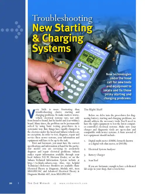
>Very little is more frustrating than troubleshooting elusive starting and charging problems.T o make matters worse,vehicle electrical systems vary,not only from brand to brand,but by model and year within a brand.Many times,the problem can be permanently solved by using basic testing procedures in a systematic way.But,things have rapidly changed in the electrics under the hood and Subaru vehicles are no exception.In order to test,diagnose,repair and service these newer systems,your information and equipment will have to be up to the task.First and foremost,you must have the correct specifications and information at hand for the partic-ular model you are servicing to accurately diagnose and repair electrical problems.Subaru makes repair information available through your local Subaru N.E.W .Horizon Dealer,or on the Subaru T echnical I nformation System website at .Also,two helpful T echnician’s Reference Booklets are available:Basic Electrical Theory & Diagnosis,Module 601,item MSA5P0134C and Advanced Electrical Theory &Diagnosis Module 602,item MSA5P0134C.The Right StuffBefore we delve into the procedures for diag-nosing battery,starting and charging problems,we should address the necessary tools.You’ll need to have the right equipment to test the latest comput-er-controlled electrical systems.Make sure your charger and diagnostic tools are up-to-date and compatible with newer systems.A basic arsenal of test equipment should include:1.Digital multi-meter (DMM,formerly known as a digital volt-ohm meter,or DVOM)2.Electrical System Analyzer3.Battery Charger4.Scan T oolIf you are fortunate enough to have a dedicated lab scope in your shop,that’s even better.20T h e E n d W r e n c h > w w w.e n d w r e n c h.c omDigital Multi-MeterLong gone are the days when checking a battery or elec-trical charging system could be performed with a simple voltmeter and test light.The sophisticated electronically-controlled systems on late model vehicles require the diag-nostic capabilities of a digital multi-meter.The most accept-able method for checking battery draw is with the use of an ammeter with an inductive pickup.DMMs usually have a DC ammeter function that will read from a few milliamps (mA) up to 10 amps.Make sure your DMM is internally fused for protection against high amperage.With the use of an induction clamp,or “amp clamp,”you can observe the ampere variance as accessory loads are applied.Electrical System AnalyzerMany new electrical system diagnostic tools are on the market today.These dedicated analyzers read the conditions existing in the electrical system and signal malfunctions or weaknesses.They also direct corrective measures and verify that the problem was eliminated by the repair.Many of these tools not only test the condition of the battery,but also monitor alternator output,check diodeA good quality multi-fun ction digital multi-meter (DMM) is essen tial for diagnosing electrical problems.Be sure to learn how to use all of its features.22|T h e E n d W r e n c h > w w w.e n d w r e n c h.c o mcondition,and find short circuits.Rate of discharge is meas-ured by internal microprocessors and compared against known standards to establish “rate of decay”and recovery ability to predict the power-holding potential and life expectancy of the battery.Another approach is to measure the conductance quality of the battery by sending a fre-quency signal through it to estimate the usable plate area,thereby determining the power retention life.Cold crank-ing capacity (CCA) is also measured,both without and under load.The end result is more accurate decisions on borderline batteries,and the identification of battery defects even at extremely low voltages,thus eliminating the time-consum-ing need to charge and retest the battery.A good example of the latest technologies for analyzing and testing the starting and charging systems is the inTELLECT EXP -1000,made by Midtronics.This handheld analyzer allows a technician to diagnose every part of the electrical system,from the battery to the starter and alter-nator.T est results can be printed out via an optional printer.The tool’s expandable platform combines the full functions of an advanced analyzer,digital multimeter (with scope mode),and data management tool.t’s upgradeable for future applications and features.Modern ChargersThe newest types of battery chargers have also been integrated with computerized logic and databases to deter-mine the quality of the battery,its life expectancy and to pro-vide optimum charging.Many can measure over 1,000 amps of starter draw using inductive amp probes,and voltage drop at connections and cables with test leads.These units can also test alternator output with carbon pile load,and detect bad diodes and faulty stators with an automatic ripple indicator.Some units even have battery decay logic programs to deter-mine battery life expectancy.The Midtronics GR-1 features “diagnostic conductance controlled charging”for solving battery problems.It tests the battery at the beginning,during and after charging.This unit effectively controls the charging process using the optimal charging voltage and current to quickly charge even weak batteries.New electrical system an alyzers,such as the Midtron ics in TELLECT EXP-1000,have made diagnosing electric system problems much easier.A n ew con ductan ce-based diagn ostics battery charger can provide quick,accurate battery testing and charging.New Starting & Charging SystemsScan ToolWhile a scan tool isn’t the first tool you may think to grab when troubleshooting a starting and charging problem, it can give you insight into any malfunctions in other areas of the vehicle that could have a bearing on the electrical prob-lem.Be sure to check the ECM for any diagnostic trouble codes (DTCs) prior to tackling the problem.It can save you a great deal of time and effort.Battery TestingBegin your troubleshooting efforts with the battery. You’ll need to determine the state of charge,the battery’s condition and its ability to hold a charge.If the battery is in good condition,it will hold a charge and deliver its rated amperage as needed.If the battery is in poor condition,it won’t deliver on demand.Use a voltmeter or DMM to check the charge level. Don’t trust the battery’s integrated charge indicator as it may only be reading one cell,not all.When fully charged,a battery should read 12.6 volts at room temperature.At 75% charged, the reading will be 12.4 volts.Lower readings indicate the need for recharging.T est the battery with an analyzer to deter-mine its condition and ability to hold a charge.If you don’t have an analyzer,recharge the battery,then retest it.The following steps can be taken to checkthe battery:O Check the battery for physical damage.O Check the positive and negative leads for corrosion and proper installation.O Check that the electrolyte is at the full level.O Check the color of the electrolyte to assess plate deterioration:•Clear means there’s no damage or deterioration.•Red means there’s positive plate deterioration.•Gray means there’s negative plate deterioration.O Check the specific gravity.It should be at least 1.230 at room temperature to test the battery.There should be no more than a .050 point differential among the cells.O On sealed maintenance-free batteries,check the open circuit voltage and compare its value with the manufac-turer’s specifications.If the specific gravity is below 1.230 or the open circuit voltage is below the recom-mended value,charge the battery and recheck the specific gravity or open circuit voltage.A u g u s t2006•N u m b e r35|23Adding JuiceBefore recharging (or replacing) a battery,check the operating condition of the charging system.Refer to the vehicle’s service manual for correct specifications.As a rule,it should read 14 volts during idle,with all acces-sories off,but may vary according the battery’s condition, charge level,load,ambient temperature and design.Cold weather will normally raise the charging level,while hot weather will normally lower it.If you have a tester with an adjustable carbon pile,you can check the charging output while the engine is operating at 2,000 rpm.AlternatorBefore testing the alternator (or installing a new one), make sure the battery is fully charged and in good condi-tion.Remember that the alternator’s job is to maintain the battery’s charge,not to recharge a faulty e a DMM or system analyzer to test the alternator output.Make sure the belt is in good condition and the tension is correct. Most electrical system analyzers and testers can also detect a faulty diode.StarterJust because a starter spins when power is applied is not an indicator that it is free from problems.In order to get an accurate reading,you’ll need to check how many amps it is drawing and measure the spin speed.It may be necessary to use a bench tester if your equipment in not capable of meas-uring the starter’s rotating rpm.Check the OE specs for the starter and compare to the unit you’re testing.Starter malfunctions can be caused by a faulty solenoid,shorts or opens in the field coil or armature, worn brushes,shaft damage or corrosion – internally or on the connections.Subaru recommends a starter performance test under these conditions:O No-load test (free spin).O Load test (under applied load).O Stall test (armature locked).While specifications will vary,we’ll use a 2000 Legacy with an automatic transmission as a typical example. Measured values must meet the following standards:O No-load test @ 11V/90 A,or more,and the rotating speed must be 3,350 rpm,or more.O Load test @ 8V/13.7 Nm (10.1 ft-lb),370 A or less, and the speed must be 880 rpms,or more.O Stall test @ 5V/1,050 A,or less,and the torque must be 27.5 Nm (20.3 ft-lb),or more.Of course,remember to consult the Subaru Service Manual for the vehicle you are diagnosing for the correct specifications.How’s the Weather?The local temperature and weather play a big part in starting and charging problems.People who live in the northern part of the country know that cold temps wreak havoc on batteries,alternators and starters — and expose any weaknesses in the system.When the mercury dips,the battery’s power is reduced by significant numbers.A fully-charged,battery is essential to spin the starter at speeds necessary to turn over the engine.Meanwhile,the engine oil has thickened and engine metal has contracted,making the job of moving the pistons,valves and the viscous oil much harder on the starter.More cranking amps are required to handle the load.At the same time,the driver may have turned on his heater/defroster,windshield wipers,rear window defog-ger,seat heaters and radio.The demand on the charging system has just maxed out!Not only does the power demand tax the system,but in many cases the electrical accessories may be the cause of elec-trical problems.When searching for elusive electrical grem-lins,first check the starting and charging system with all accessories off.If the problem is not found,one by one,turn each electrical accessory on,until the problem is isolated.Those of you who live in areas that use salt to de-ice roads need to check for salt corrosion on exposed terminals, grounds and connections.Hot climates can cause electrical system problems,too. For one thing,batteries don’t like excessive heat.Electrolyte evaporation and high temps promote battery deterioration. Also,the radiator and A/C cooling fans,blowers and the compressor clutch all add to the electrical demand.In short,extreme temperatures place high demands on the battery,starter and charger,so always take the climate into consideration during diagnosis.We’ll conclude with one crucially important,yet often overlooked,point that applies to all electrical trou-bleshooting:Always check for good grounds before you condemn any components.ONew Starting & Charging Systems24|T h e E n d W r e n c h>w w w.e n d w r e n c h.c o m。
个人的日产颐达骐达维护保养推荐(来自嘟嘟的日志)至从买了新车后4S店做了两次免费保养,觉得东西不好又贵,之后保养全都自己做,自己没设备的拿到外面做。
自己的TIIDA已过40000公里。
其间也尝试过其他品牌和型号不同的保养品,以下这些都是自己用下来不错的。
维护类发动机机油------------(每5000-10000公里)--------------------------(美孚1号5W-30全合成机油)参考价55x3=165元买一升装的,正好三瓶。
建议在5000-7500公里时换。
等爱车里程超过10万公里后换成美孚一号5W-40型号。
机油滤清器------------(每5000-7000公里)--------------------------(曼牌、改:Honeywell)参考价30元左右放干净后,用机油在滤清器口上涂抹一圈,一定要上紧后再添加。
空气滤清器------------(每5000公里清洁,1万公里更换)--------(中日富士、豹王、原厂、改:高流量)参考价30元可自己动手,在发动机右上方,说明书上有标注。
购买的时候可以选择活性炭类型的,也可以选择除臭类型的。
空调滤芯---------------(每5000公里清洁,1万公里更换)--------(豹王、索菲玛、原厂、其他)参考价50元可自己动手,拧下螺丝卸下整个手套箱,左下角就能看到了。
蓄电池---------(每2年或更长更换)--------(改:瓦尔塔免维护蓄电池6-QW-45LT1HD、旧的可抵现金)抵现后参考价300元可自己动手,想省钱的朋友无需购买蓄电池可以直接购买电解液或添加蒸馏水,说明书上有写加到什么位置。
轮胎------------(每1万公里前后换位,5万公里更换)----(改:倍耐力P6 195/60R15、或其他,旧的可抵现金)参考价550x4=2200元换位的时候最好每个轮胎做下定位。
良好的驾驶习惯和路面会延长轮胎寿命,根据实际情况更换。

A B C D E F G H I J K ML 快速参考索引A 概述信息GI概述信息B 发动机EM发动机结构LU发动机润滑系统CO发动机冷却系统EC发动机控制系统FL燃油系统EX排气系统ACC加速控制系统C 离合器/变速箱CL离合器MT手动变速箱AT自动变速箱D 传动系统/车桥FAX前桥RAX后桥E 悬架FSU前悬架RSU后悬架WT车轮和轮胎F 制动BR制动系统PB驻车制动系统BRC制动控制系统G 转向PS动力转向系统STC转向控制系统H 约束系统SB安全带SRS辅助约束系统 (SRS )I 车身BL车身、门锁和安全系统GW玻璃、车窗系统和后视镜RF车顶EI外饰和内饰IP仪表板SE座椅J 空调ATC自动空调MTC手动空调K 电气系统SC起动和充电系统LT照明系统DI驾驶信息系统WW雨刮器、洗涤器和喇叭BCS车身控制系统LANLAN 系统AV音响、视频、导航和电话系统PG 供电、接地和电路元件L 保养MA 保养M 索引IDX索引本公司保留所有权利。
事先未经东风汽车有限公司东风日产乘用车公司的书面许可,本维修手册的任何部分不得复制或存储在检索系统中,或以任何形式,任何方法传播,如使用电子、机械、录音或其他方法。
版本: 2005年4月出版号 SM5C-0C11P0前言本手册包含了东风日产乘用车公司TIIDA(颐达)系列车型的保养和修理步骤。
为了保障你的人身安全和车辆的正常使用功能必须仔细阅读本手册。
在开始修理工作前一定要透彻理解GI 部分中注意事项的内容。
出版时,本手册中的全部内容都是最新的产品信息。
本公司保留在任何时候不预先通知而变更技术参数和维修方法的权利。
重要安全须知正确的维修操作对保证维修人员的人身安全和车辆性能的可靠是至关重要的。
本手册中描述的维修步骤尽可能的使维修操作更安全准确。
维修质量依据所采用的维修步骤、工具、零部件和维修技师的经验有所不同。
如果不采用本公司推荐的维修步骤、工具或零部件,必须完全确认所选择的维修方法不会对人身安全和车辆的安全造成损害。
___骐达2008款1.6自动挡时尚型维修手册本手册是针对___骐达2008款1.6自动挡时尚型车型的维修手册。
它旨在提供详细的维修信息和操作指南,帮助车主和维修人员更好地理解和修理该车型。
手册的内容涵盖了骐达2008款1.6自动挡时尚型车型的各个方面,包括引擎系统、电气系统、传动系统、制动系统、悬挂系统、车身外观、内部装配等。
每个系统和部件都有详细的说明、技术规格和维修步骤,方便用户进行维修和保养。
通过研究本手册,车主和维修人员可以更好地了解骐达2008款1.6自动挡时尚型车型的构造和工作原理,并学会正确维修和保养方法。
本手册旨在使用户能够维持车辆的性能和安全性,并延长车辆的使用寿命。
请注意,本手册只适用于骐达2008款1.6自动挡时尚型车型,不适用于其他型号和配置的车辆。
在进行任何维修前,请务必先阅读并理解本手册中的所有说明和警告提示,并按照指导进行操作。
祝愿您在使用本手册时取得愉快和有益的经验!如有任何疑问或需要进一步的协助,请随时联系我们。
本手册的目的是为___骐达2008款1.6自动挡时尚型车主和维修人员提供一份全面且易于理解的维修手册。
通过手册中所提供的信息和指导,用户可以更加有效地维修和保养车辆,确保车辆的可靠性和安全性。
手册的目标是:提供详细的车辆结构和系统功能说明,帮助用户了解车辆的工作原理。
提供准确的维修步骤和操作指南,帮助用户正确地进行维修和保养工作。
提供技术规格和注意事项,帮助用户进行维护和故障排除。
强调安全操作和事故预防,确保用户维修过程中的安全性。
本手册的目的是为了满足用户对骐达2008款1.6自动挡时尚型车辆维修的需求,并提供一种更加便捷和可靠的解决方案。
我们希望通过本手册的使用,用户能够更加熟悉和了解他们的车辆,并能够进行正确的维修和保养。
希望这本维修手册能够给您带来实质性的帮助,并使您在维修骐达车辆时感到更加自信和满意!如果您有任何问题或需要进一步的协助,请随时联系我们。
日产骐达、颐达维修手册一、概述日产骐达、颐达是日产汽车公司的一款畅销车型,拥有良好的性能和可靠性。
为了方便广大车主和维修人员更好地了解和掌握骐达、颐达的维修保养知识,特编写本手册。
二、保养与检查1.定期更换机油和滤清器,确保发动机正常运转。
2.定期检查轮胎气压和磨损情况,确保行车安全。
3.定期检查刹车片和刹车盘的磨损情况,及时更换。
4.定期检查灯光、雨刮器等装置的工作状况,确保行车安全。
5.定期检查底盘和悬挂系统的状况,确保车辆行驶稳定性。
三、常见故障及解决方法1.发动机无法启动:检查电瓶是否亏电,检查点火开关和起动机等是否正常。
2.发动机怠速不稳:检查节气门、怠速马达是否需要清洗。
3.发动机水温过高:检查水箱是否缺水,检查风扇是否正常工作。
4.刹车失灵:检查刹车油是否缺失,检查刹车碟和刹车片是否需要更换。
5.悬挂系统异响:检查减震器和橡胶套等部件是否需要更换。
四、维修注意事项1.维修前必须充分了解车辆的结构和性能,避免盲目拆卸。
2.维修过程中要确保工具和设备的安全可靠,避免发生意外事故。
3.维修完成后要认真检查车辆的性能和外观,确保没有遗留问题。
4.维修费用要严格按照合同和保修规定执行,避免发生纠纷。
五、特殊部件维修1.发动机维修:骐达、颐达的发动机采用日产最新的技术,维修时要注意更换部件的质量和规格,确保发动机的正常运转。
2.轮胎更换:轮胎是车辆安全行驶的重要部件,更换时要选择合适的品牌和规格,确保行车安全。
3.刹车系统维修:骐达、颐达的刹车系统采用液压刹车,维修时要确保刹车油的质量和更换的正确性,避免发生刹车失灵的情况。
总之,日产骐达、颐达的维修保养是一项重要的工作,需要维修人员和车主共同努力,确保车辆的正常运转和行车安全。
通过本手册的学习,相信车主和维修人员能够更好地掌握骐达、颐达的维修保养知识,为车辆的正常运转提供保障。
骐达维修手册
骐达车型的维修手册是一个非常详细的指南,包含了所有关于骐达车型的维修和保养信息。
这本手册涵盖了车辆的各个系统,包括引擎、底盘、电气系统、车身等,并提供了详细的故障排除步骤和注意事项。
以下是维修手册的一些主要内容:
1. 车辆简介:提供了骐达车型的一般信息,包括车辆规格、性能参数和特点等。
2. 维修工具和安全信息:介绍了进行维修工作所需的工具和设备,以及确保工作安全的重要信息。
3. 发动机和传动系统:详细介绍了骐达车型的发动机和传动系统的结构和功能,包括发动机、变速器和底盘等部分。
4. 电气系统:涵盖了车辆的电气系统,包括电池、发电机、起动机、照明系统、空调系统等。
5. 车身和底盘:介绍了车辆的车身和底盘结构,包括车身、车架、悬挂系统和制动系统等部分。
6. 维修和保养:提供了各个系统的保养和维修信息,包括更换机油、更换刹车片、检查轮胎等常见维护项目。
7. 故障排除:提供了故障排除的步骤和方法,帮助维修人员快速准确地诊断和解决问题。
如果您需要购买或查阅骐达车型的维修手册,建议您联系当地的汽车维修店或相关的汽车售后服务提供商。
他们可以提供最新的维修手册,并根据您的具体需求提供相关的技术支持和服务。
26 | Nissan TechNewsNissan Supplemental Restraint SystemsDamage analysis and repair using Diagnostic Trouble CodesAll photos Courtesy of Nissan of Union City, GA FeatureSummer 2016 | 27Just as sound systems have evolvedfrom single channel mono devices to themultichannel surround sound of today, the air bags, seat belt pre-tensioners, sensors, controllers and other Supplemental Restraint System (SRS) components on Nissanvehicles have advanced to provide occupant protection during a collision. Nissan SRS is engineered to be robust and self-monitoring.Notes for TechniciansDiagnostic information in this article applies only to the Nissan year and models mentioned. Consult the service manual for the Nissan vehicle on which you are working prior to doing any repairs.Before servicing the SRS, turn the ignition switch off and disconnect both battery cables. For approximately three minutes after thecables are removed, it is still possible for the air bag and seat belt pre-tensioner to deploy. Do not work on any SRS connectors or wires until at least three minutes have passed.When working near the air bag Diagnosis Sensor Unit or the air bag system sensors with the ignition on or engine running, do not use air or electric power tools or strike near the SRS components with a hammer. The vibration could activate a sensor and deploy an air bag. Also, do not use electrical test equipment to check SRS circuits unless instructed to do so in the Nissan service manual.SRS Damage AnalysisThe electronics used in Nissan SRS self-monitoring functions are so sophisticated that almost any failure in a restraint systems component will set a diagnostic troubleSupplemental Restraint Systems (SRS) – the air bags, seat belts, associated sensors, controllers, and instrument panel indicatorlamps – include multiple layers of monitoring to help provide a 100% readiness status. Read on to familiarize yourself with some things that could light the SRS warning lamp on the instrument panel.code (DTC) and light the SRS warning lamp on the instrument panel. Pulling DTCs at the estimating stage helps identify fault codes relating to the various air bags, seat belt pre-tensioners, crash zone sensors, control modules, and other SRS components, even in cases where there is no instrument panel warning light illuminated. Some codes point to a malfunction, some identify if various air bags, seat belt pre-tensioners, and other SRS components have been deployed and must be replaced, and some indicate a need for component calibration or initialization.This information helps you get a preliminary feel for how extensively the restraint system has been damaged. It provides an efficienthead start on development of a repair plan that results in complete and safe vehicle restoration. A complete damage analysis also helps make your estimate more thorough and accurate. DTCs can indicate the need for further investigation of components or circuits that you may otherwise have missed. They can help prevent supplements for work that may have been better scheduled at an earlier point in the repair sequence, and avoid unanticipated late-stage sublets that delay job completion and increase the number of car rental days.Warning Light Does Not Tell the Whole StoryThe SRS warning light system may not provide a complete listing of system faults. Some faults may set a DTC, but not trigger a instrument panel light. A lit warning lamp does not always mean that a deployment has occurred, assome SRS malfunctions could occur without a collision. An unlit warning lamp could be hidingpreviously stored intermittent faults that do not set a current code. And sometimes the absence of a warning light could indicate a dead bulb or other lamp problem, rather than an absence of DTCs.Plug In – for a More Complete Picture When you key-on the ignition, whetherthe air bag light comes on or not, plugyour CONSULT III scan tool into the OBD II connector to get a list of all SRS fault codes. Codes that point to a specific source of the fault are relatively easy. For example, on the 2012 Altima, the codes B1033 and B1034 refer to crash zone sensor malfunctions. Diagnosis involves a visual check of the wiring harness connections, and if that is not the problem, replacement of the crash zone sensor.A broad-based code may point to an entire circuit for you to investigate in order to pinpoint the exact fault. An example on the 2012 Altima is the code B1054, which refersto an open in the driver’s air bag stage 2 circuit. That circuit includes the air bag, the Diagnosis Sensor Unit (DSU), the Spiral Cable (aka clock spring), related wiring harnesses and wires, and of course, power and ground. After replacing any faulty part, you’ll calibrate or initialize the replacement component if required, then repeat the scan. If the code does not reappear, your repair is successful.SRS Self-DiagnosisDetailed SRS self-diagnosis results can be read using a CONSULT III plus. The warning lamp default in key-on, engine-off (KOEO) operation is User mode, which provides general problem alerts that may not tell the whole story. If there are no malfunctions, the light will come on for 7 seconds, then go off. If the light stays on, an air bag or seat belt pre-tensioner has been deployed, or there is a malfunction in the ACU, the air bag power supply circuit, or the warning lamp circuit. If the light does not come on at all, either the SRS controller – an Airbag Control Unit (ACU) in Nissan parlance — or the warning lamp itself is malfunctioning.The Nissan SRS can provide more detailed diagnostic information for technicians, but you must first switch from User to Diagnostic mode (see sidebar: How to Change Self-Diagnosis Modes, p31). For a proper diagnosis, use the CONSULT III plus scan tool, as Nissan cannot verify the accuracy of other tools.Scan, Inspect, Repair, Re-scanA scan allows you to read and clear trouble codes, collect sensor and control module data, perform input and output tests, program, code, calibrate, or initialize replacement components, and conduct many other diagnostic functions. Generic scan tools may be simple code readers with only basic data collection capabilities. The CONSULT III plus is the only scan tool that enables you to perform every factory scan function needed for diagnosis and repair verification on Nissan SRS components. Additionally, it offers bi-directional communication capabilities so you can not only read, but also activate and test variousSRS and DTCsThe electrical connections between the air bagand the diagnosis sensor unit pass throughthe spiral cable. The white nib at the top of thespiral cable assembly on this 2012 Versa must becentered while the wheels are pointed straightahead, and the steering wheel held in place untilinstallation is complete.28 | Nissan TechNewsSummer 2016 | 29modules and system components, and allows you to code, re-flash or upgrade modules.Once you have pulled all SRS-related DTCs, use CONSULT III plus to look up the explanation of each code. CONSULT III plus will present alogical repair order sequence to follow for each different code, based on Nissan service manual information. (Be sure to review this information carefully.) After each step in the sequence, re-scan to confirm that the DTC is no longer present. At the first step in which your re-scan did not show the same fault code popping up again, your repair of that malfunction has succeeded, and you can clear its code from memory. If the DTC is still showing, you have further diagnostic work to do.For example, the code “B1051” for the 2012 Altima points to a possible short to ground in stage 1 of the dual-stage driver air bag module. CONSULT III plus will tell you first to visually check the stage 1 wiring harness connection, and replace the harness if it has visible damage, a poor connection, or is loose. If that does not clear the code, inspect the spiral cable circuit for damaged wiring or harness connections. Also inspect for continuity from the driver air bag moduleterminal 1 on connector M82, to terminal 29 on the spiral cable connector M29, and from the driver air bag module terminal 2 on connector M82 to terminal 30 on spiral cable connectorM29. Check to confirm that there is no continuity to ground from terminal 1 or terminal 2 on the air bagmodule connector M82. Repair as needed and re-scan using CONSULT III plus.If the same DTC reappears, replace the air bag diagnosis sensor unit, and re-check the system. If the code is still present, replace the driver air bag module, and re-scan. If the code appears again, replace the related wiring harness.Scan once again. If youmade it this far into the repair order sequence, you willhave inspected and replaced everything in the driver’s airbag stage 1 circuit, and theThe steering angle sensor mounts in the bottom of the spiral cable for this 2012 Versa. If the original SAS is undamaged, it can be transferred from the oldspiral cable and dropped into place in the new one.The pre-tensioner for the 2014 Sentra, like an air bag, ignites a gas charge that then forces a gear or ratchet to move in a direction that tightens the belt. The pre-tensioner is deployed simultaneously with the driver’s and front passenger’s air bags, and must be replaced after a front collision in which the air bags and pre-tensioner are deployed.30 | Nissan TechNewsComplex System, Simple RepairNissan’s Occupant Classification System (OCS) uses input from technology in the front passenger seat to determine if there is an occupant, and whether their weight is in the range of a young child or an adult. The information is fed to the ACU. If the front passenger is a child, the ACU may not deploy the air bag. Depending upon the crash severity and the age and model of the Nissan vehicle, if the right front seat occupant is an adult, the ACU may activate the passenger air bag in two separate stages timed a few milliseconds apart, to stagger the impact of the air bag’s explosive force against the seat occupant. The OCS in the 2012 Altima includes a sensor mat and a control module. Trouble codes B1017, B1020 and B1021 all point to a fault in the 2012 Altima’s OCS control module. Code B1018 suggests that the sensor mat is malfunctioning. Code B1019 covers any other possible causes of OCS failure. The sensor mat and control module are both built into the front passenger seat cushion, and formSRS and DTCsfault will have been eliminated. Clear the DTC, and move on to the next fault code, if any.Spiral Cable, AKA: Clock SpringThe steering wheel mounted driver’s air bag requires electrical connections to be maintained while the wheel is being turned. Nissan’s spiral cable connects both the power and ground sides of the driver air bag circuit. It winds and unwinds as the driver turns the steering wheel, all while maintaining hardwired electrical connections.All driver air bag DTCs; B1049 - B1052 and B1054 - B1057, require inspection of thespiral cable circuit if the prior diagnostic step revealed no damage to the driver air bag wiring harnesses.Inspect the spiral cable for any sign ofdamage to its wiring, connectors, or housing. Look for burns or melted connectors to the driver air bag. The ignition of gas when the air bag deploys generates enough heat to melt the plastic connectors to the spiral cable. If there is no visible damage to the harnesses, check for continuity on both the power and ground sides of the circuit. If there is continuity on the power side, but not on the ground side, the spiral cable can be re-used.Check the Nissan service manual for the exact points that must align with each other on the spiral cable and the steering wheel. The spiral cable has, in most cases, enough extra length to rotate approximately 2.5 turns in either direction. With the front wheels pointed straight ahead, the spiral cable must be installed in the neutral position of approximately 2.5 turns of the cable from either end position back to the center. If it is not centered properly during installation, it could break as the steering wheel is rotatedduring driving.The driver’s and front passenger’s air bags for most 2007 and newer Nissans are a dual-stage design that includes connections for two separate inflator circuits, one for partial inflation in a minor collision, and a second for maximuminflation in the event of a higher impact. Shown is the driver’s air bag for a 2014 Sentra.Summer 2016 | 31NOTE: In User mode, if the air bag warning light has come on for 7 seconds and then is not blinking, there is no malfunction, and the system will not switch toDiagnosis mode. In Diagnosis mode, if no malfunction is detected, you can switch back to User mode by turning the ignition from OFF to ON.Once in Diagnosis mode, the air bag warning lamp will flash on and off in a different sequence for each SRS component or system where it sees a malfunction. After the initial 7 seconds on, the lamp will begin a flash pattern that is associated with the malfunctioning component. Refer to your Nissan service manual for descriptions of all flash patterns used in the SRS warning lamp system.The warning lamp system covers additional SRScomponent faults. It uses flash patterns that are unique to each type of malfunction. The flash pattern willrepeat until you make the indicated repair, after which you can clear the code.CONSULT III plus is the Nissan factory diagnostic tool for the SRS. It records and displays the same information as the warning lamp system, plusadditional data that further narrows the diagnosticsearch. CONSULT III plus displays DTCs for individual SRS components, identifies whether the fault is likely on the power or ground side of the circuit, and points out if two circuits may be shorted together.CONSULT III plus is very useful for finding intermittent faults. An intermittent incident that occurred in the past but is not being detected currently can be reviewed by going to the SELF DIAG (PAST) option in CONSULT III plus. You can then replace the malfunctioning component and clear the code. If the incident was previously repaired but not cleared from memory, erasing it is easy using CONSULT III plus.If the warning lamp lights up, but you can find no DTC using CONSULT III plus, one likely cause is that the fault was repaired, but the trouble code was not cleared in the ACU. Clear the DTC by turning the ignition switch OFF for at least 1 second, then back ON.The Nissan Supplemental Restraint System is a multi-channel structure featuring multiple layers of protection for vehicle occupants, continuous self-monitoring, and reporting for driver notification and technician diagnostic assistance. Failure of any one SRS component will keep that vehicle in your bay, but the Nissan SRS does an excellent job of pointing you to the malfunctioning part(s). |How to Change Self-Diagnosis ModesTo switch from User to Diagnosis mode:1. Turn ignition from OFF to ON.2. Within 1 second after air bag light comes on for 7 seconds and turns off, turn the ignition switch off.3. Wait for 3 seconds.4. Repeat steps 1 to 3 two more times (total of 3 times).5. Turn ignition switch ON again. (Turn to Diagnosis mode.) Repeat the above four steps, in the same order, to switch from Diagnosis back to User mode.a single assembly. Do not attempt to disassemble the right front seat cushion assembly. The repair for any of these five different DTCs is replacement of the entire front passenger seat cushion assembly.The only circumstance in which there are OCS repair options on the 2012Altima is if your scan reveals DTC B1022, which points to a communication failure between the OCS control module and the air bag diagnosis sensor unit (DSU). Even then, the repair order sequence is brief.1. Visually check the wiring harness connection2. Replace the harness if it has visible damage3. If the DTC is still current, replace the RH front seat cushion assembly (do not disassemble)4. If the DTC is still current, replace the air bag diagnosis sensor unit (DSU)Seat Belt Pre-tensioner Diagnosis? Use Only CONSULT.Beginning with the 1999 Maxima,Nissan included seat belt pre-tensioners in the SRS, and expanded that to other models in subsequent years (check your Nissan service manual for details on which SRS components are on the vehicle in your bay). On the 2012 Altima, DTCs B1209 (front collision detection) and B1210 (side collision detection) require you to replace all seat belts,including pre-tensioners, after a collision in which pre-tensioners were deployed.It may not be easy to tell simply by visual inspection whether or not a seat belt pre-tensioner has been activated. If a pre-tensioner was deployed, but has not been replaced, the ACU will not clear the fault code. Instrument panel warning lights can’t tell you the deployment status of a given pre-tensioner. You’ll need to use CONSULT to determine which pre-tensioners have been activated.。