2031A快速使用说明
- 格式:pdf
- 大小:286.42 KB
- 文档页数:2

频率均衡器在歌舞厅和厅堂扩声中应用很多,其本要作用有:1.校正音响设备产生的频率畸变,能补偿各种节目信号中欠缺的频率成分,又能抑制过重的频率成分;2.校正室内声学共振特性产生的频率畸变,弥补建筑声学的结构缺陷;3.抑制声反馈,改善厅堂扩声的质量;4.修饰或美化音色,提高音质和音响效果。
例如,在厅堂扩声或歌舞厅音响系统安装完毕后,由于厅堂声学共振而使扩声系统(包括传声器、放大器、音箱、房间的传输特性)的频率特性曲线起伏很大,这时就可借助频率均衡器房间均衡器),通过提升(或衰减)由于厅堂对某些频率而造成的谷点(或峰点),使总响应特性趋于平坦,这就是所谓镜像均衡。
对于存在声反馈的扩声系统,在均衡处理之前,要使扩声系统稳定,最大增益只能开大到使频响曲线中最大峰点接近自激之处。
此时,除最大峰点附近很窄频段外,大部分频段内扩声增益都很低,常常不能足使用要求。
借助频率均衡器处理后,大的峰点被消除,频率特性变均匀了,使所有频率点的扩声增益都有相当大的提高。
至于利用频率均衡器来修饰音色,提高音质是大家所共知的。
三、均衡器的主要技术指标(一)频率点数(段数)均衡器的中心频率设置台前所述,是有一定规律的,例如倍频程1/2倍频程和1/3倍频程等。
通常,频率点数越多,其频带宽度越窄,(即Q值越高)。
(二)均衡量亦即控制范围,它是指均衡器对中心频率所对应信号的最大提升提升或最大衰减量,常用分贝表示。
其规格有±6dB、±12dB、±15dB、±18dB等。
数值越大,表示控制能力越强。
图1-2-1图示均衡器的控制曲线(三)谐波失真度通常要求谐波失真应不大于0.1%。
(四)等效输入噪声级这是与信噪比相对应的指标、其值越小,信噪比越好。
通常要求等效输入噪声不大于)-90dB。
(五)对于参量均衡器还有Q值和中心频率调整范围Q值又称品质因数。
Q值越高,均衡器提升或衰减曲线越尖锐,带宽也越窄;反之,Q值越低,带宽越宽。

LOREX Live Connect Wireless Skype Home Surveillance ReviewOctober 25, 2011The LOREX Technology Live Connect LW2031 Series is a cool Skype-powered home surveillance system sporting night vision (via IR LEDs) and full color H.264 video. It can be used both for home surveillance, but also as a baby monitor due to its night vision and its portable handheld monitor sporting a color 2.4" LCD. It seemed like an interesting Skype product so I had LOREX send me a LW2031 to review.InstallationInstalling this was pretty straightforward. Two of the three devices - camera & handheld monitor use mini-USB power adapters, which are included. The gateway device uses a 5V AC adapter, which is also included. They ship the rechargeable batteries in the camera and the handheld monitor partially charged, so I only needed to hook up power to the gateway initially. I also connected the included Ethernet cable. I powered on the handheld device and in seconds I was able to see the video feed from the camera, which ships already "paired" to the gateway. You can pair up to 4 cameras. Local viewing on handheld monitor supports up to 4 cameras in auto-sequence mode (one camera at a time) or selectable single camera viewing. In just two minutes I had everything out of the box and working.Hooking up SkypeThe only thing that might trip up potential buyers is that they need to have two Skype usernames. One personal one and an additional Skype username to assign to the LOREX Live Connect system. Fortunately, their instructions are very good and the Getting Started single sheet spells this out very clearly. The next part of the Getting Started guide is to launch to the web interface of the gateway. It's actually pretty simple since it leverage UPnP. All you have to do it click Start, Computer, Network, thenunder Other Devices I was able to see "LOREX Gateway". Then you simple double-click which opens the IP address into your default browser.LOREX Web Admin InterfaceThe web interface asked for a timezone and then asked if I had a Skype name. I already have test Skype accounts, but I was curious what the "user experience" was for users without multiple Skype usernames, so I selected the option for no Skype username. It then allowed me to register a new Skype username without having to leave this interface, go to and register there. Definitely a nice touch to make it as easy as possible.After registering the new Skype username, I logged into Skype using these new credentials. I then added a new contact - my primary/personal Skype username. I logged out, then logged in with my primary Skype username and accepted the contact request. Now I was ready to call the Lorex Live Connect over Skype!I made a call and the Lorex Live Connect gateway automatically answered the call and began transmitting video in about 15 seconds. This was really my own complaint with the product - that it took 15s before video began. Fortunately, audio is near instantaneous.Lights on vs. Lights offThe video quality was pretty good. I captured a video (using iPhone 4s) of the video call, including some video of the handheld monitor and uploaded it to YouTube, which you can watch here:I should point out that the YouTube video I took above was taken with my office lights off, and my window shades closed since I was trying to duplicate "baby monitor" type conditions - or at least very low-light conditions. Though it wasn't pitch dark, my office was pretty dark, so I was pretty amazed thatin low-light conditions and even with the IR sensors not kicked in (not quite dark enough), that the video quality was pretty good. You obviously get more "noise" in a video when taken in a darkened room, so to be fair and to get an accurate representation of the quality of the video in a brightened room I also snapped this screenshot with my office lights on:As you can see, the quality is pretty good. You can even make out my greying sideburns. Oh and the Monster Pump Creatine mix on my shelf. I liked that the camera was very rotational allowing you to get just the right angle. The back of the base has a hole allowing you to wall-mount the camera. The camera microphone was quite sensitive and easily picks up the slightest sound even 20 feet away, making it very useful as a baby monitor or to covertly listen in on conversations!The handheld monitor, which features a 2.4" color LCD is a handy little device for when you're home and want to monitor a room or area, such as a playpen or crib. It had pretty good range in my testing and they claim 150 foot range. The color quality was pretty decent and the frame rate was pretty good as well. Here's a sample photo of it:Interestingly, the handheld monitor sports a microSD memory slot on the side and the unit ships with a 1GB microSD memory card, as well as a microSD adapter for connecting to your PC. From the handheld monitor you can kick off an impromptu video recording by pressing the camera icon button for 5s. The handheld monitor records 320x240 video but it doesn't support audio recording. Though if you really insist on recording audio, there are plenty of Skype add-ons that support both video and audio recording to your PC.Because the system leverages Skype, you can use your smartphone, tablet (i.e. iPad), PC, or Mac to view the video and listen to the audio. Initially my new iPhone 4S running Skype had problems when calling the LOREX Live Connect. The call connected, but then after about 15s it tried to initialize video and then it just dropped the call. The audio worked for the first 15s or so before the call dropped. I rebooted my 4S and tried again and then it worked. Damn iPhone! I also tried it on an iPad 2 and it worked fine on the first try.Features & SpecificationsVideo camera:• Image Sensor: CMOS• Image Resolution: 640 x 480 up to 20fps• Automatic night-vision up to 22ft• Minimum Illuminat ion: 0 Lux (IR on)• View Angle: H: 64°, V: 48°• Built-in rechargeable lithium battery for portable use (4 hrs battery life)• Power adapter included for continuous non-portable use.• Secure, private Digital Wireless video & audio• Built-in microphone for listen-in audioHandheld monitor:• Color 2.4" LCD• 640x480 resolution• Compact design with rechargeable lithium battery for trueportability• Snap, store and share pictures and video with microSD recording• Expandable up to 4 cameras• Digital Wi reless range up to 150ft indoors. Actual range may vary depending on obstructions.Internet Gateway:• Remote viewing via Skype compatible devices (PC, Mac,iPhone 4/3GS, iPad/iPad 2)• H.264 video compression for efficient internet streamingConclusionThe LIVE CONNECT LW2031 Series is an certainly an easy-to-use portable home monitor and surveillance system. It will retail for $299.99, which is a bit of a premium. Just for price comparison, I searched Amazon for baby monitor with night vision and the products range from $80 to over $269, however even the most expensive one doesn't support Skype. So when you combine the portable handheld monitor for local monitoring, the night vision feature, support for four cameras, and the Skype capabilities, this certainly makes for a worthy home surveillance choice.very rotational - xyzLights vs. Lights offThe YouTube video I took was taken with the lights off, and my window shades closed. You obviously get more "noise" in a picture in a darkened room, so to be fair and to get an accurate representation of the quality of the picture in a brightened room I also snapped this screenshot:As you can see, the quality is pretty good. You can even make out my greying sideburns./liveconnect/A SOLUTION FOR HOME AND AWAY.Use the system at home with the handheld monitor or connect when you are away fromhome via Skype™ using your smartphone, tablet, PC or Mac.*Connect over the Internet via Skype• View on th e go with iPhone & iPad• Wireless portability• Clear video—day and night• Easy to use and set upVideo camera:• High resolution image sensor for clear video• Built-in rechargeable lithium battery for portable use1• Automatic night-vision up to 22ft2• Secure, private Digital Wireless video & audio3• Built-in microphone for listen-in audioHandheld monitor:• Color 2.4" LCD Display• Compact design with rechargeable lithium battery for trueportability1• Snap, store and share pictures and video with microSD™ recording4• Expandable up to 4 cameras5Internet Gateway:• Remote viewing via Skype™ compatible devices (PC, Mac,iPhone™ 4/3GS, iPad/iPad 2™)*• H.264 video compression for efficient internet streaming• Connects easily to your internet router1. Rechargeable battery life up to 4 hours. Battery pre-installed in the camera. Power adapter included for continuous non-portable use.2. Stated IR illumination range is based on ideal conditions. Actual range and image clarity depends on installation location, viewing area and light reflection/absorption level of object3. Digital Wireless range up to 150ft indoors. Actual range may vary depending on obstructions.4. microSD™ memory card and SD card adapter included. Resolution limited to 320x240, for viewing on handheld monitor or sharing on social media sites. Audio recording not supported5. Local viewing on handheld monitor up to 4 cameras in auto-sequence mode (one camera at a time) or selectable single camera viewing. Additional cameras sold separately (model: LW2030AC1).* Internet monitoring via Skype requires registration for a free Skype account for both gateway and personal account. Remote viewing over the internet requires high speed internet and arouter (not included). Mobile charges may apply if accessing through cellular network, check with your local service provider. You cannot simultaneously watch video on handheld monitor andremotely via Skype™. Handheld monitor for local viewing takes priority, however a notification will show you that someone wants to connect remotely. See manual for more details.Transmission Frequency: ISM 2,400~2,483.5 MHzTransmission Power: 18dBmUnobstructed Effective Range: 450ft / 135mSpread Spectrum: FHSSModulation Mode: GFSKOperating Tempurature: 32 ~ 122° Fahrenheit /0 ~ 50° Celsius)Operating Humidity: Less than 90%Camera:Image Sensor: CMOSTotal Picture Pixels: H: 640, V: 480Minimum Illumination: 0 Lux (IR on)Night Vision Distance: 22 FT (7m)View Angle: H: 64°, V: 48°Image Resolution: 640 x 480 up to 20fpsPower Consumption (Max.): 700mAPower Supply: 5V DCDimensions (W x D x H): 66mm x 95mm x 115mm / 2.6” x 3.8” x 4.6”Weight: 0.5 lbs / 0.3 kgHandheld Monitor:Image Sensor: CMOSTotal Picture Pixels: H: 640, V: 480Minimum Illumination: 0 Lux (IR on)Night Vision Distance: 22 FT (7m)View Angle: H: 64°, V: 48°Image Resolution: 640 x 480 up to 20fpsPower Consumption (Max.): 700mAPower Supply: 5V DCDimensions (W x D x H): 66mm x 95mm x 115mm / 2.6” x 3.8” x 4.6”Weight: 0.5 lbs / 0.3 kgTMCNet – Tom Keating requested a Lorex LIVE CONNECT to review. The article ran on Tuesday, October 25th: /blog/tom-keating/skype/lorex-live-connect-wireless-skype-home-surveillance-review.asp.。

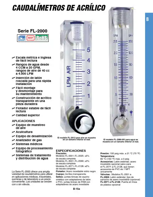
La Serie FL-2000 ofrece una amplia variedad de caudalímetros para utilizar en aplicaciones médicas, industriales, químicas y de laboratorio a un precio conveniente. Las unidades se venden con o sin válvula.CAUDALÍMETROS DE ACRÍLICOB-15aESpEciFicacionES precisión:Modelos FL-2001–FL-2025: ±5%de escala completa Modelos FL-2031–FL-2069: ±3% de escala completaModelos FL-2071–FL-2128: ±2% de escala completaFlotador: Acero inoxidable vidrio negro cuerpo: Acrílico transparente Sellos: Juntas tóricas de caucho sintético con adaptadores de latón o PVC, juntas tóricas de FKM con adaptadores de acero inoxidablepresión: 100 psig máx. a 21 °C (70 °F)Temperatura:65 °C (150 °F) máx. a 0 psigaccesorios: Latón estándar, acero inoxidable opcional salvo para el FL-2071 a FL-2128, que tienen accesorios de PVC de 1 NPT únicamenteVálvulas: Modelos FL-2001 a FL-2069: Latón estándar; tipo decartucho de acero inoxidable (opcional) FL-2071 a FL-2128: Puerta en línea de plástico opcionalU E scala métrica e inglesa de fácil lectura U R angos de agua desde 4 ccM a 20 GpM,rangos de aire de 40 cc a 4.000 LpM U i nserción de latónroscada para una rápida instalación U F ácil montajey desmontaje para su mantenimiento U c onstrucción de acrílico transparente en una pieza duradera U F lotador estable de fácil lectura U c alidad superiorapLicacionES U E quipo de muestreo de aireU a cuiculturaU Equipo de desalinización U a nalizador de gasU S istemas médicos U E quipo de procesamientofotográficoU S istemas de tratamiento y distribución de aguaEl modelo FL-2013 para aire se muestraen un tamaño inferior al real.El modelo FL-2066-nV para agua se muestra en un tamaño inferior al real.B(13,5)B-15bDimensiones de FL-2091 hasta FL-2128Para solicitar el producto con válvula de compuerta de plástico, añada el sufijo “-V” al número de modelo para ver el coste adicional para las Series FL-2090 y FL-2120.Para un certificado NIST de 10 puntos opcional, añada el sufijo “-NIST” al número de modelo, con coste adicional y dos semanas más al plazo de entrega estándar .Ejemplo de pedido: FL-2095, rotámetro, 100 a 1.400 LPM de aire FL-2127-V, rotámetro, 4 a 36 LPM de agua, con válvulas.El modelo FL-2097 se muestra en un tamaño inferior al real.Se trata de unidades estándar sin válvulas.Para solicitar el producto con válvula de compuerta de plástico, añada el sufijo “-V” al número de modelo para ver el coste adicional.Para un certificado NIST de 10 puntos opcional, añada el sufijo “-NIST” al número de modelo, con coste adicional y dos semanas más al plazo de entrega estándar.Ejemplos de pedidos: FL-2075, válvula de rotámetro, 100 a 1.400 LPM de aire.FL-2080, válvula de rotámetro, 2 a 19 LPM de agua.El modelo FL-2041-nV se muestra en un tamaño inferioral real.El modelo FL-2053 para agua se muestra en un tamaño inferioral real.El modelo FL-2066-nV se muestraen un tamaño inferior al real.Para solicitar el producto con válvula de acero inoxidable, añada el sufijo “-SS” al número de modelo para ver el coste adicional.Para solicitar el producto sin válvula, añada el sufijo “-NV” al número de modelo y descuéntelo del coste.Para un certificado NIST de 10 puntos opcional, añada el sufijo “-NIST ” al número de modelo, con coste adicional y dos semanas más al plazo de entrega estándar.Ejemplos de pedidos: FL-2036, rotámetro económico, con válvula de latón, 14 a 150 SCFH de aire.FL-2036-NV , rotámetro económico, sin válvula de latón, 14 a 150 SCFH de aire.BEl modelo FL-2060 para airese muestra en un tamaño inferior al real.Escalas dobles de modo estándar: SCFM/SCFH, GPM/GPH y LPM/LPH Para solicitar el producto con válvula de acero inoxidable, añada el sufijo “-SS” al número de modelo para ver el coste adicional.Para solicitar el producto sin válvula, añada el sufijo “-NV” al número de modelo y descuéntelo del coste.Para un certificado NIST de 10 puntos opcional, añada el sufijo “-NIST” alnúmero de modelo, con coste adicional y dos semanas más al plazo de entrega estándar.Ejemplos de pedidos: FL-2060, rotámetro con válvula de latón, 0,5 a 5 scfm. FL-2069-NV, rotámetro sin válvula, 2 a 20 LPM.El modelo FL-2091 paraaire se muestra en un tamaño inferior al real.B-15cEl modelo FL-2021-nV para agua se muestra en un tamaño superior al real.Para solicitar el producto con válvulas de acero inoxidable, añada el sufijo “-SS”al número de modelo para ver el coste adicional.Para solicitar el producto sin válvula, añada el sufijo “-NV” al número de modelo y descuéntelo del coste.Para un certificado NIST de 10 puntos opcional, añada el sufijo “-NIST” al número de modelo, con coste adicional y dos semanas más al plazo de entrega estándar.Ejemplos de pedidos: FL-2005, rotámetro económico con válvula de latón, 2 a 20 SCFH de aire.FL-2005-NV, rotámetro económico sin válvula, 2 a 20 SCFH de aire.B-15d。
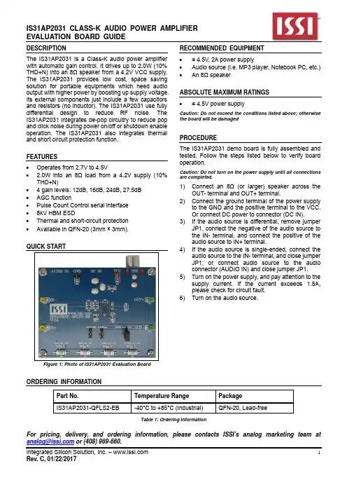
DESCRIPTIONThe IS31AP2031 is a Class-K audio power amplifier with automatic gain control. It drives up to 2.0W (10% THD+N) into an 8Ω speaker from a 4.2V VCC supply. The IS31AP2031 provides low cost, space saving solution for portable equipments which need audio output with higher power by boosting up supply voltage. Its external components just include a few capacitors and resistors (no inductor). The IS31AP2031 use fully differential design to reduce RF noise. The IS31AP2031 integrates de-pop circuitry to reduce pop and click noise during power on/off or shutdown enable operation. The IS31AP2031 also integrates thermal and short circuit protection function.FEATURES∙ Operates from 2.7V to 4.5V∙ 2.0W into an 8Ω load from a 4.2V supply (10%THD+N)∙ 4 gain levels: 12dB, 16dB, 24dB, 27.5dB ∙ AGC function∙ Pulse Count Control serial interface ∙ 8kV HBM ESD∙ Thermal and short-circuit protection ∙ Available in QFN-20 (3mm × 3mm).QUICK STARTFigure 1: Photo of IS31AP2031 Evaluation BoardRECOMMENDED EQUIPMENT∙ ≤ 4.5V, 2A power supply∙ Audio source (i.e. MP3 player, Notebook PC, etc.) ∙ An 8Ω speakerABSOLUTE MAXIMUM RATINGS ∙≤ 4.5V power supplyCaution: Do not exceed the conditions listed above; otherwise the board will be damagedPROCEDUREThe IS31AP2031 demo board is fully assembled and tested. Follow the steps listed below to verify board operation.Caution: Do not turn on the power supply until all connections are completed.1) Connect an 8Ω (or larger) speaker across theOUT- terminal and OUT+ terminal.2) Connect the ground terminal of the power supplyto the GND and the positive terminal to the VCC. Or connect DC power to connector (DC IN).3) If the audio source is differential, remove jumperJP1, connect the negative of the audio source to the IN- terminal, and connect the positive of the audio source to IN+ terminal.4) If the audio source is single-ended, connect theaudio source to the IN- terminal, and close jumper JP1; or connect audio source to the audio connector (AUDIO IN) and close jumper JP1.5) Turn on the power supply, and pay attention to thesupply current. If the current exceeds 1.5A, please check for circuit fault. 6) Turn on the audio source.ORDERING INFORMATIONPart No.Temperature Range PackageIS31AP2031-QFLS2-EB-40°C to +85°C (Industrial)QFN-20, Lead-freeTable 1: Ordering InformationFor pricing, delivery, and ordering information, please contacts ISSI’s analog marketing team at or (408) 969-660.PERFORMANCE DESCRIPTIONThe IS31AP2031 evaluation board has four buttons to switch between the different modes. The operating mode is indicated by an LED illuminated above the appropriate buttons. The modes listed as below: 1) Mode1: gain level 12dB AGC OFF. 2) Mode2: gain level 16dB AGC ON. 3) Mode3: gain level 24dB AGC OFF. 4) Mode4: gain level 27.5dB: AGC ON.5)Shutdown mode: close Jumper (JP2) enter shutdown mode.Note: IS31AP2031 Audio Amplifier provides solely the Audio function on the evaluation board.SOFTWARE SUPPORTPlease refer to the integrated program.Note: The Jumper JP3 is closed by default, if the JP3 is open, the MCU will stop functioning, the SDB pin of the chip in a high impedance state. The external MCU can be used to control the board SD (TP7) point.Please refer to the datasheet to get more information about IS31AP2031.Figure 2: IS31AP2031 Application SchematicBILL OF MATERIALSNo.Name Symbol Description QtySupplier PartAudio Amplifier U1 Class-K Audio Amplifier 1 ISSI IS31AP2031PAM PAM31011RegulatorLDO U2Low-dropoutNXP LPC922 MCU U3Microcontroller 1Everlight19-217/BHC-ZL1M2RY/3T Diode D1~D4 Diode, LED Blue, SMD 4RES,10k,1/16W,±1%,SMD 2 Yageo RC0603FR-0710KRL Resistor R1,R2RES,100k,1/16W,±5%,SMD 6 Yageo RC0603JR-07100KRL Resistor R3,R5,R10~R13RES,1k,1/16W,±5%,SMD 4 Yageo RC0603JR-0701KRL Resistor R6~R9Connected 1NotResistor R4CAP,10µF,10V,±10%,SMD 2 Yageo CC0805KKX7R6BB106 Capacitor C1,C61µF,16V,±10%,SMD 1 Yageo CC0603KKX7R7BB105CAP,Capacitor C21µF,16V,±10%,SMD 2 Yageo CC0805KKX7R7BB105CAP,Capacitor C8,C10CAP,15nF,16V,±10%,SMD 2 Yageo CC0603KKX7R7BB153 Capacitor C3,C44.7µF,10V,±10%,SMD 1 Yageo CC0805KKX7R6BB475CAP,Capacitor C5CAP,0.1µF,16V,±10%,SMD 1 Yageo CC0603KKX7R7BB104Capacitor C7CAP,10nF,16V,±10%,SMD 1 Yageo CC0603KKX7R7BB103 Capacitor C9SMD 4Button K1~K4ButtonBill of Materials, refer to Figure 2 above.Figure 4: Board PCB Layout - Top LayerFigure 6: Board PCB Layout - Bottom LayerCopyright © 2017 Integrated Silicon Solution, Inc. All rights reserved. ISSI reserves the right to make changes to this specification and its products at any time without notice. ISSI assumes no liability arising out of the application or use of any information, products or services described herein. Customers are advised to obtain the latest version of this device specification before relying on any published information and before placing orders for products.Integrated Silicon Solution, Inc. does not recommend the use of any of its products in life support applications where the failure or malfunction of the product can reasonably be expected to cause failure of the life support system or to significantly affect its safety or effectiveness. Products are not authorized for use in such applications unless Integrated Silicon Solution, Inc. receives written assurance to its satisfaction, that:a.) the risk of injury or damage has been minimized;b.) the user assume all such risks; andc.) potential liability of Integrated Silicon Solution, Inc is adequately protected under the circumstances。

增压空气压缩机使用说明书Model: BC1631A BC1621BC2031A BC2021BC3031 BC1221BC2631SM005-03敬告!●切勿直接呼入由此压缩机产生的压缩空气或气体。
●压缩机应在通风良好的区域内使用。
切勿在雨中、潮湿区域或靠近爆炸环境下来使用压缩机。
●检查电动机铭牌,确定电动机是否适合当地的供电条件(电压- 相位- 频率)在进行任何维护或修理工作之前,一定要断开电源线。
●切勿使压缩机在可能有爆炸或易燃蒸汽的任何区域内运行。
在压缩机或储气罐的附近,严禁烟火,不得使用明火。
●擅自改变储气罐的结构,会导致其强度减弱,从而造成其破裂或爆炸,并造成严重的人员伤亡。
压力超过设计极限会导致储气罐破裂或爆炸,并造成严重的人员伤亡。
不正确使用气体工具和附件,会导致爆炸,并造成严重的人员伤亡。
储气罐安装安全阀,以防止过压。
切勿对安全阀进行拆卸、调节。
定期拉动安全阀的拉环,以确保其自由动作,如果阀门卡涩或不能自由动作,则必须予以更换。
●每天或每次使用前应排放掉储气罐内的冷凝水。
切勿试图对压力开关进行调节、拆卸或加旁路,或者对任何压力控制的有关装置进行改变或修改。
●旋转的压缩机会带动污物、砂子、金属屑等,并造成严重的人身伤害。
切勿将空气喷嘴或空气喷射器指向身体的任何部分或指向其他人员。
●在进行任何维护或修理工作之前,一定要确保压缩机、储气罐和空气附件内的压力均已释放掉。
当风扇防护罩已拆下、已受损或破裂时,切勿操作压缩机。
●压缩机运转时会发烫。
如果触及,会造成严重烫伤。
当压缩机运转或压缩机停机不久时,切勿触及压缩机、电机/发动机或其管道。
压缩机不得在包装箱底板上运行!目录第一章概述------------------------1 应用------------------------------------1第二章安装------------------------2 位置和基础---------------------------2 进气管路------------------------------2 机组安装------------------------------2 起动器---------------------------------3 线路------------------------------------3 保险丝---------------------------------4 排气管路------------------------------4第三章调整------------------------5 自动启动和停止控制---------------5 压力开关调整------------------------5 恒速控制------------------------------5第四章操作------------------------6 操作检查------------------------------6 压缩机润滑---------------------------6 润滑油更换---------------------------6 润滑油使用建议---------------------6 电动机润滑和维护------------------6 后冷却器------------------------------6启动卸载系统------------------------6 呼吸器管------------------------------7第五章故障检查说明------------8第六章维修保养-------------------10 日常检查和维护----------------------10概述-------------------------------------11 气阀清洗-------------------------------11 皮带安装和调整----------------------12 力矩值----------------------------------13 长期停机的保护措施----------------13第七章选配件设备和附件-------14单向阀----------------------------------14 自动冷凝排放阀----------------------14 定时自动冷凝水排放系统----------14 储气罐----------------------------------15第八章控制箱操作说明---------16压缩机机组示意图说明:1、增压机必须每天检查润滑油及油质、油位。

Para la versión en español, visite /supportMeet your phone.About your phoneSetting up your phoneYour phone already has a SIM card installed.Charge the PhoneBefore turning on your phone, charge it fully.Your phone comes with an Adaptive Fast Charging charger and a USB cable. Plug the smaller end of the cable into the USB/charger port on your phone and the larger end into the charger. Then plug the charger into an electrical outlet to charge the phone.NOTE: Devices and software are constantly evolving—the screen images and icons you see here are for reference only.Samsung and Galaxy S are trademarks of SamsungElectronics Co., Ltd. Android, Google, the Google logo and Google Play are trademarks of Google Inc. Screen imagessimulated. Appearance of device may vary.Volume Buttons+-Recent Apps HeadsetJackHomeBackSIM/microSDCard TrayFront CameraRear CameraUSB/Charger PortWARNING: Use only Samsung-approved charging devices. Samsung accessories are designed to maximize battery life. Using other accessories may invalidate your warranty and may cause damage.Optional: Insert the microSD card.1. With the screen facing up, insert the tool that came with your phone into the hole on the SIM/microSD card tray to open it.2. Carefully slide out the tray.3. Insert the microSD card into the tray with the gold strips facing down (as shown).4. Insert the tray back into the slot and carefully push the tray in until it’s closed completely.NOTE: The microSD card is sold separately.Power/ Lock ButtonUsing your phoneTurning your phone on/offTo turn your phone on, press and hold the Power/Lock button.Press and hold the Power/Lock button again to turn it off.Locking/unlocking the screenTo turn on your screen, press the Power/Lock button and then swipe up on the screen to unlock it.To turn off your screen and prevent accidental key presses, press the Power/Lock button.Printed in Korea .GH68-45568A _REV_1.1MicrophoneTop of phoneHome screen modeYou can select one of the two modes: Easy and Standard. Instructions in this guide are written using Standard mode.Standard mode is for users who are familiar with Android.Easy mode is a simplified experience for the first-time smartphone user.1.> > From the Home screen, tap Apps > Settings > Easy mode .2. Choose the mode you want to use and tap Done .Managing your a ccountMy Verizon Mobile appManage your account, track your usage, edit account information, pay your bill and more.International travelFor features and rates when outside the US, visit/international .Customer service Call 1.800.922.0204 Twitter @VZWSupportAdditional i nformationYour wireless device and third-party servicesVerizon Wireless is the mobile carrier associated with this wireless device, but many services and features offered through this device are provided by or inconjunction with third parties. Verizon Wireless is not responsible for your use of this device or any non-Verizon Wireless applications, services and products, including any personal information you choose to use, submit or share with others. Specific third-party terms and conditions, terms of use and privacy policies apply. Please review carefully allapplicable terms, conditions and policies prior to using this wireless device and any associated application, product or service.Hearing aid compatibility informationThis phone has been tested and rated for use with hearing aids for some of the wireless technologies that it uses. However, there may be some newer technologies that have not been tested yet for use with hearing aids. It is important to try the different features of this phone thoroughly and in different locations, using your hearing aid or cochlear implant, to determine if you hear any interfering noise. Ask your service provider or the manufacturer of this phone for information on hearing aid compatibility. If you have questions about return or exchange policies,ask your service provider or phone retailer.© 2016 Verizon Wireless. All Rights Reserved.The Help app gives you tips,videos and other information on how to use your phone, including:Making calls Voice mail Sending texts Getting apps Taking photosAccessibilty settingsFrom your computer, visit/support .Download a User Guide from/support or call 1.888.987.HELP to order a copy.Learning moreAdvanced CallingYou can make High-Definition Voice and Video Calls and surf the web while you talk on the phone when you add Advanced Calling to your line. Visit /AdvancedCalling to learn how.Copying content from your old phone For help transferring contacts, photos and other content from your old phone wirelessly, visit /cloud .Or, to transfer content using the USB On the Go connector that came with your new phone, select Smart Switch during setup or open it later from the Home screen by tapping Apps > Settings > Backup and reset > Open Smart Switch .Visit /smartswitch for more information and a list of compatible phones.USB connector USB cableOld Device New Galaxy。

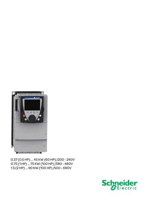
0.37 (0.5 HP) ... 45 KW (60 HP) /200 - 240V 0.75 (1 HP) ... 75 KW (100 HP) /380 - 480V 1.5 (2 HP) ... 90 KW (100 HP) /500 - 690V施耐德变频器参数设置93相电机 200...240 V 三相电源电压:200…240 V 50/60 Hz3相电机 200...240 V (1)这些功率额定值与电流额定值是在环境温度为50°C (122°F),以出厂设置的开关频率连续运行的情况下给出的(对于ATV71H 037M3 至D15M3X 变频器,开关频率出厂设置为4 kHz ;对于ATV71H D18M3X 至D45M3X 变频器,开关频率出厂设置为2.5 kHz)。
在以比出厂设置值高的开关频率工作时,如果温升过高,变频器就会自动降低开关频率。
对于高于出厂设置的连续运行,变频器必须按照第14页的曲线来降低额定电流。
(2)标有“最大预期短路电流Isc ”的线路电源上的电流,且变频器不带任何外部选件。
(3)在最大电压(240 V +10%)下上电时的峰值电流。
(4)ATV71H037M3 至D45M3X 变频器使用时可带或不带图形显示终端。
没有图形显示终端的变频器目录编号后面加字母Z , 例如:ATV71H075M3Z 。
变频器在恶劣的环境条件下工作时不能使用此选件(5)。
(5)带有S337 或337 扩展名的变频器设计用于在恶劣的环境条件下使用(3C2 类,符合IEC721-3-3),配备有图形显示终端。
(6)必须使用线路电抗器(请参考目录)。
(7)带有383 扩展名的变频器用于同步电机。
为了使ATV71H 075M3至U75M3变频器能够在单相电源下工作,必须禁止输入缺相故障(IPL) (参见编程手册)。
如果此故障处理保持为它的出厂配置,变频器就会锁定在故障模式。
923D 4C 型小型限動開關N小型、體薄、高密封性Q 取得EN 、UL 、CSA 規格。
Q 符合JIS 的防浸、防塵、耐油構造標準和IEC 的IP67項目最高水準的密封性。
Q 柱塞部分採用丁月青橡膠膜片、內裝開關部採用丁月青橡膠保護帽的三重密封結構。
Q以附有2m 、3m 、5m 的S-FLEX VCTF 為標準,具有優良的耐油、耐寒、耐熱、屈曲性。
同時附有UL 、CSA 規格承認電纜的開關也已達系列化。
Q 安裝用螺絲可適用M5型,並可多連安裝。
Q帶有LED 指示燈的開關已達系列化,易於確認動作狀態。
(以不動作時點亮為標準)QVCTF 耐油纜線規格,符合CE 標誌之對應品(限標準型適用)認定海外規格*1. 只有VCTF 耐油電纜型取得。
*2. 只有SJT(O)電纜型取得。
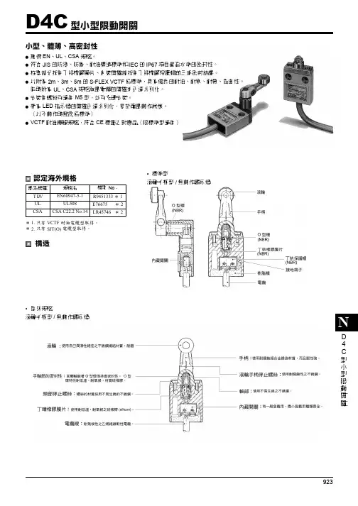
構造•屋外規格滾輪手柄型/無動作顯示燈認定機關規格名檔案 No ﹒T V EN60947-5-1R9451333*1UL UL508E76675 *2CSACSA C22.2 No.14LR45746 *2•標準型滾輪手柄型/無動作顯示燈Ü D4C 型小型限動開關D4CD 4 C種類Q無動作顯示燈註:1. 耐寒規格也有準備,型式請參考下面例子。
<例> D4C-1201——D4C-1201-C交期及價格請另外洽詢。
2. 耐粘性油規格(附濾油孔)也有準備。
型式如下面例子,(只有柱塞型才有)<例> D4C-1201——D4C-1201-M3. 可變滾輪手柄型也有準備,請另外洽詢。
*1. 耐油性佳之乙烯絕緣纜線*2. 一般之乙烯絕緣纜線*3. SJT(O)電纜(UL,CSA規格承認電纜)全部為UL,CSA規格承認電纜,均標有標準品印章。
額定纜線傳動軸種類纜線長標準型微小負載型AC250V 5ADC30V 4A ACl25V 0.1A DC30V 0.1AVCTF耐油纜線*1VCTF*2SJT(O) *3VCTF耐油纜線*1VCTF*2型式型式型式型式型式柱塞型2D4C-1801型D4C-1901型—D4C-4801型D4C-4901型3D4C-1201型D4C-1401型D4C-1601型D4C-4201型D4C-4401型5D4C-1301型D4C-1501型D4C-1701型D4C-4301型D4C-4501型滾輪柱塞型2D4C-1802型D4C-1902型—D4C-4802型D4C-4902型3D4C-1202型D4C-1402型D4C-1602型D4C-4202型D4C-4402型5D4C-1302型D4C-1502型D4C-1702型D4C-4302型D4C-4502型交叉滾輪柱塞型2D4C-1803型D4C-1903型—D4C-4803型D4C-4903型3D4C-1203型D4C-1403型D4C-1603型D4C-4203型D4C-4403型5D4C-1303型D4C-1503型D4C-1703型D4C-4303型D4C-4503型斜面柱塞型2D4C-1810型D4C-1910型—D4C-4810型D4C-4910型3D4C-1210型D4C-1410型D4C-1610型D4C-4210型D4C-4410型5D4C-1310型D4C-1510型D4C-1710型D4C-4310型D4C-4510型滾輪手柄型2D4C-1820型D4C-1920型—D4C-4820型D4C-4920型3D4C-1220型D4C-1420型D4C-1620型D4C-4220型D4C-4420型5D4C-1320型D4C-1520型D4C-1720型D4C-4320型D4C-4520型滾輪手柄型高感度型2D4C-1824型D4C-1924型—D4C-4824型D4C-4924型3D4C-1224型D4C-1424型D4C-1624型D4C-4224型D4C-4424型5D4C-1324型D4C-1524型D4C-1724型D4C-4324型D4C-4524型密封鞘柱塞型2D4C-1831型D4C-1931型—D4C-4831型D4C-4931型3D4C-1231型D4C-1431型D4C-1631型D4C-4231型D4C-4431型5D4C-1331型D4C-1531型D4C-1731型D4C-4331型D4C-4531型密封滾輪柱塞型2D4C-1832型D4C-1932型—D4C-4832型D4C-4932型3D4C-1232型D4C-1432型D4C-1632型D4C-4232型D4C-4432型5D4C-1332型D4C-1532型D4C-1732型D4C-4332型D4C-4532型密封交叉滾輪柱塞型2D4C-1833型D4C-1933型—D4C-4833型D4C-4933型3D4C-1233型D4C-1433型D4C-1633型D4C-4233型D4C-4433型5D4C-1333型D4C-1533型D4C-1733型D4C-4333型D4C-4533型面板安裝式銷柱塞型2D4C-1841型D4C-1941型—D4C-4841型D4C-4941型3D4C-1241型D4C-1441型D4C-1641型D4C-4241型D4C-4441型5D4C-1341型D4C-1541型D4C-1741型D4C-4341型D4C-4541型面板安裝式滾輪柱塞型2D4C-1842型D4C-1942型—D4C-4842型D4C-4942型3D4C-1242型D4C-1442型—D4C-4242型D4C-4442型5D4C-1342型D4C-1542型D4C-1742型D4C-4342型D4C-4542型面板安裝式交叉滾輪柱塞型2D4C-1843型D4C-1943型—D4C-4843型D4C-4943型3D4C-1243型D4C-1443型D4C-1643型D4C-4243型D4C-4443型5D4C-1343型D4C-1543型D4C-1743型D4C-4343型D4C-4543型塑膠桿型2D4C-1850型D4C-1950型—D4C-4850型D4C-4950型3D4C-1250型D4C-1450型D4C-1650型D4C-4250型D4C-4450型5D4C-1350型D4C-1550型D4C-1750型D4C-4350型D4C-4550型中心滾輪手柄型2D4C-1860型D4C-1960型—D4C-4860型D4C-4960型3D4C-1260型D4C-1460型D4C-1660型D4C-4260型D4C-4460型5D4C-1360型D4C-1560型D4C-1760型D4C-4360型D4C-4560型924925D4CD 4CQ有動作顯示燈(紅色)(標準型)註:海外規格認證請另外洽詢。
General DescriptionThe MAX2031 evaluation kit (EV kit) simplifies the evalua-tion of the MAX2031 WCDMA, cdma2000®, GSM, and WiMAX (SM)base-station up/downconversion mixer. It is fully assembled and tested at the factory. Standard 50ΩSMA connectors are included on the EV kit’s input and output ports to allow quick and easy evaluation on the test bench.This document provides a list of test equipment required to evaluate the device, a straightforward test procedure to verify functionality, a description of the EV kit circuit,the circuit schematic, a bill of materials (BOM) for the kit,and artwork for each layer of the PC board.Featureso Fully Assembled and Testedo 50ΩSMA Connectors on Input and Output Ports o 815MHz to 1000MHz RF Frequency Range o 960MHz to 1180MHz LO Frequency Range o DC to 250MHz IF Frequency Range o 7dB Conversion Loss o +36dBm Input IP3o +27dBm Input 1dB Compression Point o 7dB Noise Figureo Integrated LO Buffero Integrated RF and LO Baluns o Low -3dBm to +3dBm LO DriveoBuilt-In SPDT LO Switch with 49dB LO1 to LO2Isolation and 50ns Switching Timeo External Current-Setting Resistor Provides Option for Operating Mixer in Reduced Power/Reduced Performance ModeEvaluates: MAX2031MAX2031 Evaluation Kit________________________________________________________________Maxim Integrated Products 119-3810; Rev 0; 8/05For pricing, delivery, and ordering information,please contact Maxim/Dallas Direct!at 1-888-629-4642, or visit Maxim’s website at .Ordering Information*EP = Exposed paddle.WiMAX is a service mark of , Inc.cdma2000is a registered trademark of Telecommunications Industry Association.E v a l u a t e s : M A X 2031Quick StartThe MAX2031 EV kit is factory configured as an upcon-verter and tuned for an 810MHz RF frequency. This is accomplished by including components L1 and C4 on the PC board (see the Modifying the EV Kit section for details.The MAX2031 EV kit is fully assembled and factory tested.Follow the instructions in the Connections and Setup sec-tion for proper device evaluation.Test Equipment RequiredThis section lists the recommended test equipment to verify the operation of the MAX2031. It is intended as a guide only, and substitutions may be possible.•One DC supply capable of delivering +5.0V and150mA •Three RF signal generators capable of delivering 10dBm of output power in the 100MHz to 1GHz fre-quency range (i.e., HP 8648)•One RF spectrum analyzer with a 100kHz to 3GHz minimum frequency range (HP 8561E)•One RF power meter (HP 437B)•One power sensor (HP 8482A)Connections and SetupThis section provides a step-by-step guide to testing the basic functionality of the EV kit. As a general pre-caution to prevent damaging the outputs by driving high-VSWR loads, do not turn on DC power or RF signal generators until all connections are made.This procedure is specific to operation in the cellular band high-side-injected LO for upconverter operation to an 810MHz RF signal. Choose the test frequency based on the particular system ’s frequency plan, and adjust the following procedure accordingly. See Figure 1 for the mixer test setup diagram.1)Calibrate the power meter. For safety margin, use apower sensor rated to at least +20dBm, or use padding to protect the power head as necessary.2)Connect 3dB pads to DUT ends of each of the twoRF signal generators ’ SMA cables. This paddingimproves VSWR, and reduces the errors due to mis-match.3)Use the power meter to set the signal generatorsaccording to the following:•IF signal source: 0dBm into DUT at 160MHz (approximately 3dBm before the 3dB pad)•LO1 signal source: 0dBm into DUT at 970MHz (approximately 3dBm before the 3dB pad)•LO2 signal source: 0dBm into DUT at 969MHz (approximately 3dBm before the 3dB pad)4)Disable the signal generator outputs.5)Connect the IF source (with pad) to the IF port.6)Connect the LO1 and LO2 signal sources to the EVkit LO inputs.7)Measure loss in the 3dB pad and cable that will beconnected to the RF port. Losses are frequency-dependent, so test this at 810MHz (the RF frequen-cy). Use this loss as an offset in all output power/gain calculations.8)Connect this 3dB pad to the EV kit ’s RF port con-nector and connect a cable from the pad to the spectrum analyzer.9)Set DC supply to +5.0V, and set a current limit ofaround 150mA if possible. Disable the output voltage and connect the supply to the EV kit (through an ammeter, if desired). Enable the supply. Readjust the supply to get +5.0V at the EV kit. There will be a volt-age drop across the ammeter when the mixer is drawing current.10)Select LO1 by connecting LOSEL (TP3) to GND.11)Enable the LO and the RF sources.The procedure for downconverter operation from RF to the IF band is similar to the steps listed above. For downconverter operation, connect the RF signal source (with pad) to the RF port and connect a 3dB pad and cable to the IF port from the spectrum analyzer.MAX2031 Evaluation Kit 2_______________________________________________________________________________________Testing the Mixer Adjust the center and span of the spectrum analyzer to observe the RF output tone at 810MHz for upconverter operation. The level should be about -10dBm (7dB con-version loss, 3dB pad loss). The spectrum analyzer’s absolute magnitude accuracy is typically no better than ±1dB.Disconnect the GND connection to LOSEL. It will be pulled high by a pullup resistor on the board, selecting LO2. Observe that the 809MHz signal increases while the 810MHz decreases.Reconfigure the test setup using a combiner or hybrid to sum two of the frequency sources to do a two-tone IP3 measurement if desired. Terminate the unused LO input in 50Ω.Detailed Description The MAX2031 is a high-linearity up/downconverter inte-grated with RF and LO baluns, an LO buffer, and an SPDT LO input select switch. The EV kit circuit uses the MAX2031 and consists mostly of supply-decoupling capacitors, DC-blocking capacitors, a current-setting resistor, and an IF balun. The MAX2031 EV kit circuit allows for thorough analysis and a simple design-in.Supply-Decoupling Capacitors C2, C7, C8, and C11 are 82pF supply-decoupling capacitors used to filter high-frequency noise. C3, C6, and C9 are larger 0.01µF capacitors used for filtering lower frequency noise on the supply.DC-Blocking Capacitors The MAX2031 has internal baluns at the RF and LO inputs. These inputs have almost 0Ωresistance at DC, so DC-blocking capacitors C1, C10, and C12 are used to prevent any external bias from being shunted directly to ground.LO Bias The bias current for the integrated LO buffer is set with resistor R1 (523Ω±1%). Increasing the value of R1 can reduce the DC current of the device but the device would operate at reduced performance levels (see the Modifying the EV Kit section).TAP Network The TAP pin for the internal balun is grounded.IF±The MAX2031 mixer has a DC to 250MHz IF frequency range. Note that these differential ports are ideal for providing enhanced IIP2 performance. Single-ended IF applications require a 1:1 balun to transform the 50Ωdifferential IF impedance to 50Ωsingle-ended. After thebalun, the IF return loss is better than 15dB. The differ-ential IF is used as an input port for upconverter opera-tion. The user can use a differential IF amplifier follow-ing the mixer but a DC block is required on both IFpins.Tuning Networks The performance of the MAX2031 is enhanced with theaddition of external tuning networks. Capacitor C4 andinductor L1 form a bandpass filter network that enhancesthe linearity performance when the mixer is used toupconvert an IF port signal to the RF port. This network isconstructed on the kit and limits the usable RF band-width to approximately 750MHz to 850MHz (refer to theMAX2031 data sheet). This network can be tuned toaccommodate other RF bands if desired.Capacitor C5 is used to improve the linearity perfor-mance of the MAX2031 when the mixer is used todownconvert an RF port signal to the IF port. The valueof this cap could change slightly depending on the RFand LO frequencies.Capacitor C5 is not required for upconverter operationand the C4/L1 network is not required for downconverteroperation.LOSEL The EV kit includes a 47kΩpullup resistor (R2) for easyselection of the LO port. Providing a ground at TP3selects LO1, and leaving TP3 open selects LO2. Todrive TP3 from an external source, follow the limitscalled out in the MAX2031 device data sheet. Logicvoltages should not be applied to LOSEL without the+5V supply voltage. Doing so can cause the on-chipESD diodes to conduct and could damage the device.Layout Considerations The MAX2031 evaluation board can be a guide for boardlayout. Pay close attention to thermal design and closeplacement of components to the IC. The MAX2031 pack-age exposed paddle (EP) conducts heat from the deviceand provides a low-impedance electrical connection tothe ground plane. The EP must be attached to the PCboard ground plane with a low thermal and electricalimpedance contact. Ideally, this is achieved by solderingthe backside of the package directly to a top metalground plane on the PC board. Alternatively, the EP canbe connected to an internal or bottom-side ground planeusing an array of plated vias directly below the EP. TheMAX2031 EV kit uses nine evenly spaced, 0.016in-diam-eter, plated through holes to connect the EP to the lowerground planes.Depending on the ground plane spacing, large sur-face-mount pads in the IF path may need to have theEvaluates: MAX2031 MAX2031 Evaluation Kit_______________________________________________________________________________________3E v a l u a t e s : M A X 2031ground plane relieved under them to reduce parasitic shunt capacitance.Modifying the EV KitThe standard kit is configured as an upconverter and includes the band-limiting C4/L1 network. This network is tuned to produce the best results from 750MHz to 850MHz. This network can be tuned to the desired RF band by changing the values of L and C.If the kit is to be used as a downconverter, then C4 and L1 can be removed. Capacitor C5 should be installed to improve the downconverter linearity performance.This capacitor might need to be tuned slightly depend-ing on the RF and LO frequency bands of interest.The DC current of the device can be reduced if reduced performance is acceptable. Reducing the current is accomplished by increasing the value of R1. Doubling the value of R1 cuts the DC current approximately in half.Approximately 10% of the overall IC current is used for housekeeping (R1 set at 523Ω) and cannot be reduced.MAX2031 Evaluation Kit 4_______________________________________________________________________________________Figure 1. Test Setup DiagramEvaluates: MAX2031MAX2031 Evaluation Kit_______________________________________________________________________________________5Figure 2. MAX2031 EV Kit SchematicE v a l u a t e s : M A X 2031MAX2031 Evaluation Kit 6_______________________________________________________________________________________Figure 3. MAX2031 EV Kit PC Board Layout—Top SilkscreenFigure 4. MAX2031 EV Kit PC Board Layout—Top SoldermaskFigure 5. MAX2031 EV Kit PC Board Layout—Top Layer MetalFigure 6. MAX2031 EV Kit PC Board Layout—Inner Layer 2(GND)Maxim cannot assume responsibility for use of any circuitry other than circuitry entirely embodied in a Maxim product. No circuit patent licenses are implied. Maxim reserves the right to change the circuitry and specifications without notice at any time.Maxim Integrated Products, 120 San Gabriel Drive, Sunnyvale, CA 94086 408-737-7600 _____________________7©2005 Maxim Integrated ProductsPrinted USAis a registered trademark of Maxim Integrated Products, Inc.Evaluates: MAX2031MAX2031 Evaluation KitFigure 7. MAX2031 EV Kit PC Board Layout—Inner Layer 3(Routes)Figure 8. MAX2031 EV Kit PC Board Layout—Bottom LayerMetalFigure 9. MAX2031 EV Kit PC Board Layout—BottomSoldermask Figure 10. MAX2031 EV Kit PC Board Layout—Bottom Silkscreen。
杭州中一检测研究院有限公司崂应2031型智能大流量TSP(PM10)采样器操作规程HSG-HJ-09-2015编制人:审核人:批准人:日期:2015年01月26日发布2015年01月26日实施崂应2031型智能大流量TSP(PM10)采样器的操作规程1 项目名称崂应2031型智能大流量TSP(PM10)采样器的操作规程。
2 适用范围本采样器应用滤膜称重法捕集环境大气中的总悬浮微粒(TSP)和可吸入颗粒物(PM10)。
可供环保、卫生、劳动、安监、军事、科研、教育等部门用于气溶胶常规监测。
3 编制依据崂应2031型智能大流量TSP(PM10)采样器的使用说明书。
4 仪器的工作环境以及自身参数4.1 工作环境:4.1.1 温度:(-20~45)℃4.1.2 湿度:(0~95)%RH4.1.3 工作电源:AC(220±22)V,50Hz4.1.4 大气压力:(86~106)kPa4.1.5 适用环境:非防爆场合4.1.6 工作电源接地线应良好接地4.1.7 野外工作时,应有防雨、雪、尘以及日光暴晒等侵袭的措施4.2 自身参数指标详见表1。
表 1 主要技术指标5 仪器的使用与注意事项5.1 采样前准备5.1.1 选择采样点,平稳放置采样器,将支架两边的两个螺钉取下,用手扶好控制箱,将采样头翻转回上面,再将螺钉装回固定好。
注:此操作需要两人操作,采样器在翻转过程中要仔细缓慢,注意安全!5.1.2 采样器在野外长期采样时,底角应采取固定措施,防止被大风刮倒。
5.1.3 TSP采样安装:打开采样器顶盖,松动4个紧固螺钉,取下压板,取出滤膜夹,将已恒重并编号的滤膜(毛面朝向“1压框”的方向)装入滤膜夹内,将滤膜夹(滤膜的毛面迎对气流的方向)装入采样器,装上压板,再将4个紧固螺钉扭紧,关闭采样器顶盖。
滤膜夹装配方法如图3。
1.压框2.滤膜3.托网注:滤膜的毛面迎对气流的方向,禁止装反。
图3 滤膜夹装配示意图5.1.4 PM10采样安装:需松动4个紧固螺钉,取下压板,将装配好的PM10切割器装在滤膜夹上方,将4个紧固螺钉扭紧,关闭采样器顶盖。
P A R T S B R E A KDO W NP A R T S B R E A K D O W N *SPOA10, SPO10, SPOA7 Hybrid, &Shockwave™ Models(500, 700, And 800 Series Lifts)Capacity 10,000 lbs.2*Arm Restraint Kit (1 Arm) Includes items 13, 14, 15, 16, 19 & 58. Also includes Restraint Gears and attaching hardware (items 21, 22 & 23) from Arm Detail section.**Two different power units were used. Please verify your model number before ordering parts.1. L.H. Column Standard Weldment ............................N752 L.H. Column Seismic Weldment ..............................N7662. R.H. Column Standard Weldment ............................N755 R.H. Column Seismic Weldment ..............................N7683. Column Extension Standard Height ......................................................N470 EH-1 MODEL ...........................................................N471 EH-2 MODEL ...........................................................N472 EH-4 MODEL (SPO10 only) .....................................N4744. Carriage Yoke Weldment ..........................................N8225. Arm Pin ........................................................................N21546. 1/4"-20NC x 3/4" Lg. HHCS .........................................400997. Hydraulic Cylinder 68" Rise .....................................................................N3156 71" Rise .....................................................................N3828. Power Unit 1Ø 60Hz .......................................................**P1302/P3302 1Ø 50Hz .......................................................**P1389/P3389 3Ø .................................................................**P1347/P3347 3Ø 575V .......................................................**P1359/P3359 3Ø 380V (S Model) .....................................**P1510/P35109. Power Unit Hose ........................................................FJ837 10. 5/16”-18NC x 1-1/2” Flanged HHCS (Full Thread) .40509 11. NA .................................................................................NA 12. 5/16”-18NC Hex Flanged Lock Nut ..........................40678 13. Actuator Pin Handle ..................................................FJ7985-1 14. Actuator Pin ................................................................N121-1 15. Retaining Pin ...............................................................N119-3 16. Arm Restraint Spring .................................................FJ7656-2 17. Bleeder Screw (Specify Manufacturer) ................N/A18. Carriage Bumper ........................................................FA941 19. Arm Restraint Pawl ....................................................N2121 20. Approach bumper ......................................................FJ7391-1 21. 5/8"-11NC Nylon Insert Lock Nut .............................40743 22. Truarc #5304-75 Klipring for 3/4” Shaft . (41411)23. Sheave .........................................................................N377 24. 1/4”-20NC Zinc Hex Nut ............................................40627 25. Sheave Cover .............................................................N119-1 26. 1/4”-20NC x 3/8” Lg. PHMS Plated (2 pcs.) ............40063 27. Slider block .................................................................FJ7360 28. 3/4” Concrete Anchor ...............................................FJ7380 29. 1-1/2” O.D. x .760-.770” I.D. x .045” Bushing ..........41388 30. 1/4"-20NC x 2-3/4" HHCS ............................................40114 31. 1/4”-20NC Insert Locknut .........................................40642 32. 1/8” x 1” Lg. Cotter Pin (3Ø only) .............................41200 33. Switch Bar Assembly 1Ø SPOA10NB .........................................................N415 1Ø SPOA10/SPO10 / 3Ø w/ Push Button ..............N467 3Ø ...............................................................................N434 34. Wheel Spotting Dish Kit ............................................FF729 35. 1/4" Flat Washer .........................................................40795 36. 3/8”-16 NC x 3/4” Long Flanged HHCS ...................40124 *37. Arm Restraint Kit (1 arm) ..........................................*N2148 38. Overhead HoseStandard ...................................................................N3103 EH-1 MODEL ............................................................FJ842 EH-2 MODEL ............................................................FJ843 EH-4 MODEL (SPO10 only) .....................................FJ84539. Equalizer CablesSPOA10NB ...............................................................N384 SPOA10NB EH-1 MODEL .......................................N385 SPOA10NB EH-2 MODEL .......................................N386 SPOA10 .....................................................................N372 SPOA10 EH-1 MODEL .............................................N378 SPOA10 EH-2 MODEL .............................................N373 SPO10 ........................................................................N374 SPO10 EH-1 MODEL ................................................N379 SPO10 EH-2 MODEL ................................................N375 SPO10 EH-4 MODEL ................................................N376 40. Capacitor Box .............................................................FA7147-1 Capacitor Box Cover Plate .......................................FA7366-1 Drum Switch ...............................................................FA7364 Drum Switch Lever ....................................................FA7364-1 M5 x 45 PHMS, Plated ...............................................41672 41. Locking Latch Cable ..................................................FJ7600 42. Cable Guide .................................................................N618 43. 3/8”-16NC Flanged Locknut ......................................40664 44. Sheave Shaft ..............................................................FJ7444-8 45. Actuator Assembly (3Ø) ............................................N432-5 46. Cable End Bracket .....................................................N619 47. Hose Clip .....................................................................N38348. L.H. Overhead Assembly (Outer) .............................N480 49. R.H. Overhead Assembly (Inner) .............................N481 50. Branch Tee ..................................................................FJ7668 51. Column Mounting Bracket .......................................N439 52. 3/8"-16NC x 3/4" Carriage Bolts ...............................N/A 53. 1/4”-20NC Flanged Locknut ......................................40641 54. 3/4” Spacer ................................................................FJ7871 55. Cutoff Switch Assembly 1Ø / 3Ø w/ Push Button ..........................................N413 3Ø ...............................................................................N432 Cutoff Switch 1Ø / 3Ø w/ Push Button ..........................................N413-1 3Ø ...............................................................................N432-1 56. 1/4” External Tooth Lockwasher..............................40779 57. 1/4”-20NC x 1” HHCS Grade 5 ..................................40108 58. Spring Pin-1/4" dia. x 1-1/2" Lg. (Stainless) ............14427 59. Shim .............................................................................FJ716-6 60. Front Shim ...................................................................FJ7659-3345/16”-18NC x 1/2” HHCS4078040062407793Ø POWER UNITFA9147 Includes Items:FA9147-1 3Ø Control Box Enclosure with GasketFA9147-2 25 AMP Contactor, 3 Pole with 480 Volt Coil GE CR553AB3CAA FA9147-6 Contactor Coil DB1AB 208-240 Volt for Contactor GE CR553A FA9147-8 Switch Momentary Push Button with Contact Block FA9147-9 Cord 600 Volt 4-Wire 42” Long with Ring TerminalsFA9147-12 550-600 Volt Coil GE Pin PB1AD for 575 Volt Lifts Only51.Adapter RackFJ61272.3-1/2" (90mm) Adapter Extension FJ6171-13.5-1/4" (130mm) Adapter ExtensionFJ6171-2SPOA10 Plan ViewSPO10 Plan View1.Front ArmSPOA10 (5GX Series)*N2224 2.Rear ArmSPOA10 (5GX Series) & (5BX Series)*N2225 3.Stop Bolt Assembly N2194.Arm Restraint Gear N21225.3/8" Spring Washers (For Lifts With TappedBearing Bar)40818 6.3/8"-16NC x 1-1/2" HHCS Grade 5402017Low Profile Adapter Assembly FJ6202 Rubber Pad FJ6202-3671.Front ArmSPOA10 (5BX Series)*N22852.Rear ArmSPOA10 (5GX Series) & (5BX Series)*N22253.Stop Bolt Assembly N2194.Arm Restraint GearN2122 5.3/8" Spring Washers (For Lifts With Tapped Bearing Bar)408186.3/8"-16NC x 1-1/2" HHCS Grade 5402017Low Profile Adapter Assembly FJ6202Rubber PadFJ6202-381.Front ArmSPOA10 (70X Series)*N22772.Rear ArmSPOA10 (70X Series)*N22763.Stop Bolt 3/8"-16NC x 1/2" Lg. HHCS 401264.Arm Restraint GearN21225.3/8" Spring Washers (For Lifts With Tapped Bearing Bar)40818 6.3/8"-16NC x 1-1/2" HHCS Grade 5402017Adapter Pin FJ61798.Adapter Swivel Pin FJ79-69.High Step Adapter FJ617710.Low Step AdapterFJ617811.3/32" Hog Ring for 1/2" Shaft (8 required)FJ671-612.Front Stop Bolt (M10 x 1.5 x 20mm BHCS)41650Front ArmSPOA10 (70X Series)A10i (70X Series)Rear ArmSPOA10 (70X Series)A10i (70X Series)91.Front And Rear Arm SPO10 (5TX Series)*N22732.Rear ArmSPO10 (70X Series)*N22783.Stop Bolt 3/8"-16NC x 1/2" Lg. HHCS 401264.Arm Restraint GearN21225.3/8" Spring Washers (For Lifts With Tapped Bearing Bar)408186.3/8"-16NC x 1-1/2" HHCS Grade 5402017Adapter PinFJ61798.Adapter Swivel Pin FJ79-69.High Step Adapter FJ617710.Low Step AdapterFJ617811.3/32" Hog Ring for 1/2" Shaft (8 required)FJ671-612.Front Stop Bolt (M10 x 1.5 x 20mm BHCS)N2264-1513.Adapter Assembly (SPO10) 3-Stage Arm FJ6214Rubber PadFJ6158-414.Front and Rear Arm SPO10 (5GX Series)*N226515.Low Profile Adapter Assembly FJ6202Rubber PadFJ6202-3SPO10 (70X Series)S10i (70X Series)101.Front ArmSPOA10 (5TX Series)*N23412.Rear ArmSPOA10 (5TX Series)*N23423.Stop Bolt Assembly N2194.Arm Restraint GearN2122 5.3/8" Spring Washers (For Lifts With Tapped Bearing Bar)408186.3/8"-16NC x 1-1/2" HHCS Grade 5402017Adapter Assembly 3-Stage Arm FJ6214Rubber PadFJ6158-41.Front ArmSPOA10 (5TX Series)*N2295 2.Rear ArmSPOA10 (5TX Series)*N22943.Stop Bolt Assembly N2194.Arm Restraint Gear N21225.3/8" Spring Washers (For Lifts With TappedBearing Bar)40818 6.3/8"-16NC x 1-1/2" HHCS Grade 540201 7Adapter Assembly 3-Stage Arm FJ6202 Rubber PadFJ6202-3ITEM QTY PART NO.DESCRIPTION11401573/8"-16NC x 3/4" Lg HEX SOC BHCS, GRD224401741/4 x .475 BLIND RIVET McMASTER-CARR #97517A651 or EQ.3640192#10-24NC x 3/4 Lg. PHILLIPS TRUSS HEAD SCREW, PLATED 4640633#10-24NC HEX FLGD WZLOCK NUT, PLTD 51408433/8" INT TOOTH LW, PLTD 64412025/32" x 1" Lg COTTER PIN 72FC134-33RAMP CHOCK SLIDE 82FC5179-5PIN91FJ2494FRONT PAD RUBBER PAD102N22492-POST PAD LIFT RAMP WELDMENT 111N2338-6FRONT PAD INNER ARM WELDMENT 121N2338-13FRONT PAD INNER ARM ACTUATOR BAR 131N2338-16INNER ARM ACTUATOR ROD THUMB SCREW 141N2339-1LEFT HAND FRONT PAD WELDMENT 151NP1039USE TRUCK ADAPTER NAMEPLATE 161NP623RUBBER PAD ADAPTER NAMEPLATE 171NP874CAPACITY 1750 LBS NAMEPLATE181N2338RIGHT HAND FRONT PAD WELDMENTRIGHT HAND PADLEFT HAND PADN2393A10 REAR N2394A10 FRONT N2395O10ITEM DESCRIPTION PART 1High Step Adapter FJ6177 2Low Step Adapter FJ6178 3Adapter Pin FJ6179 43/32" Hog Ring For 1/2" Shaft FJ671-6 5Adapter Insert T120309 6Load Plate Weldment FJ6233 7Adapter Insert Pin T130669 8Swivel Pin T130668 9Low Profile Round RA Adapter FJ6219 10Truck Adapter T110564 11Extension Adapter Kit (Sold Separately)T100271 127/64" x 3/4" Cotter Pin41205I TEM DESCR I PT I ON PART#1. Control Side Cover ............................................................FJ74522. Locking Latch Dog ............................................................N6163. Control Plate ......................................................................FJ7594-24. Spring ..................................................................................FJ7566-105. Spring ..................................................................................FJ7382-96. Latch Shaft .........................................................................FJ7382-347. Locking Latch Sheave ......................................................FJ73228. Handle .................................................................................FJ7382-189. Ball Handle .........................................................................FC134-9110. Truarc Klipring #5304-75 for 3/4" Shaft (41411)11. Truarc Klipring #5304-37 for 3/8" Shaft (41410)12. 1-1/2" O.D. x 3/4" I.D. x .045" Mach. Bush. (41388)13. 5/16"-18NC x 3/8" Lg. PHMS (40227)14. 3/8" - 16NC Hex Jam Nut (40658)15. Slot Cover ...........................................................................N61716. Locking Latch Cable .........................................................FJ760017. 3/8" Flat Washer (40820)I TEM DESCR I PT I ON PART#1. Latch Cover ........................................................................FJ74512. Locking Latch Dog ............................................................N6163. Control Plate ......................................................................FJ7594-24. Spring ..................................................................................FJ7566-105. Spring ..................................................................................FJ7382-96. Latch Shaft .........................................................................FJ7382-347. Locking Latch Sheave ......................................................FJ73228. Latch Cable Clamp ............................................................N63-19. Truarc Klipring #5304-75 for 3/4" Shaft (41411)10. Truarc Klipring #5304-37 for 3/8" Shaft (41410)11. 1-1/2" O.D. x 3/4" I.D. x .045" Mach. Bush. (41388)12. 5/16"-18NC x 3/8" Lg. PHMS (40227)13. Locking Latch Cable .........................................................FJ7600DC CONTROL MOUNTINGITEM PART NO.DESCRIPTION1401673/8"-16NC x 1" Lg. CAR. BOLT, Gr. 5, PLTD.2402175/16" USS FLAT WASHER, PLTD3402215/16"-18NC x 1" Lg HHCS, GRD5 PLTD440650#12-24NC HEX NUT, PLTD5406785/16"-18NC HEX FLGD WZLOCK NUT, PLTD6FA997-1#10-32 x 1/4" Lg. HEX WHSFTS, PLTD, COLORED GREEN 741526#12-24NC x 3/4" Lg. PHIL. PHMS, PLTD841527#12 EXT TOOTH LW, PLTD9629888TY-RAP CABLE TIE, NYLON, BLACK, 11 110EFX60010319ADAPTER, STRAIGHT THREAD/ SWIVEL (ORB/ORFS 6X6)11FA7180-31WIRE GROMMET12FA7189-143/8" NPT STRAIN RELIEF13FA7189-153/8" NPT LOCKNUT14FA7616BATTERY-BATTERY CABLE15FA7958-28CORD GRIP16FA997JUNCTION BOX17FA966DC CONTROL ASSEMBLY18FA966-16BATTERY TRAY19FA966-47BATTERY CABINET 2-POST SPLASH SHIELD20FA966-5110FT UNIVERSAL POWER CORD (NEMA 5-15P TO IEC320C13) 21FA966-55BATTERY CABINET UPPER MOUNTING BRKT WELD22FA966-56BATTERY CABINET MOUNTING BRKT WELD23FA966-57BATTERY CABINET MOUNTING COLUMN BRKT WELD24FA979POSITIVE BATTERY TERMINAL END25FA980-1DUPLEX RECEPTACLE COVER 4" SQUARE BOX26FA980-2DUPLEX FEMALE RECEPTACLE27FA980-3GROUND WIRE28FA981NEGATIVE BATTERY TERMINAL END29FJ71003FLOW REGULATOR30FJ71007MALE ORFS x FEMALE ORFS SWIVEL ELBOW31FJ7669COLUMN HOSE CLAMP32a P3577DC POWER UNIT - PAD LIFT32b P3579DC POWER UNIT - ARM LIFT32c P3586DC POWER UNIT - SPO1233N3151Y HYDRAULIC CYLINDER34FJ7352-3ADAPTER35N539BASE PLATE COVER (FOR SPOA10 & SPO10 MODELS ONLY) 36402715/16”-18NC x 1-1/2” HHCS FULL THREAD37406705/16”-18NC HEX NUTDC CONTROLITEM PART NO.DESCRIPTION 1400771/4"-20NC x 1" Lg FLGD HEX SOC BHCS, GRD2 2400941/4"-20NC x 1/2" Lg FLGD HEX SOC BHCS3NA NA4406411/4"-20NC HEX FLGD WZLOCK NUT, PLTD 5407791/4" EXT TOOTH LW6FA7618DISCONNECT-FUSE CABLE7FA7619FUSE-CONTACTOR CABLE8FA7667BATTERY-DISCONNECT CABLE9FA7668BATTERY-MOTOR CABLE10FA966-22CLIP-ON NUT11FA966-341-1/4" HOLE PLUG12FA966-37BATTERY CABINET LH FRAME ASSY13FA966-39BATTERY CABINET TOP COVER WELDMENT14FA966-42BATTERY CABINET BOTTOM COVER WELDMENT 15FA966-45BATTERY CABINET FRONT BOTTOM COVER16FA966-46BATTERY CABINET SMALL BOTTOM COVER17FA966-48BATTERY CABINET LOWER SHELF ASSEMBLY 18FA986-1BATTERY CABINET RH FRAME ASSEMBLY19FA966-50BATTERY CABINET FRONT TOP COVER ASSY20FA966-58BATTERY CABINET SHELF WELD21FA970CONTACTOR HARNESS22FA971OVERHEAD HARNESS23FA978DISCONNECT HARNESS24FA982GROUND WIRE25FA966-60TRANSPARENT HOLE PLUG21LEFT HAND FRAME ASSEMBLYITEM PART NO.DESCRIPTION 141628#4-40 NYLON INSERT LOCKNUT MMC #90633A005 2796443#4-40 x 1/2 Lg. PHMS, PLTD3FA966-17SPLASH SHIELD4FA966-18DOME HEAD RIVET5FA966-21SPACER6FA966-52BATTERY CABINET LH FRAME FORMING7FA983CHARGER INTERNAL POWER CORD22LOWER SHELF ASSEMBLYITEM PART NO.DESCRIPTION 1400941/4"-20NC x 1/2" Lg FLGD HEX SOC BHCS 2406411/4"-20NC HEX FLGD WZLOCK NUT, PLTD 3450957#8-32NC NYLON LOCK NUT440022#8-32NC x 1/2" LG. PHMS5FA966-6224V 8A CHARGER ASSEMBLY6FA966-58BATTERY CABINET SHELF WELD7FA976DC CONTACTOR2324I TEM DESCR I PT I ONPART#1. Straight Adapter ..............................................FJ7352-325Note: FA9160-15 not shown26ITEM QTY PART NO.DESCRIPTION12FA793-3SWIVEL ELBOW 1/8” NPTF (MALE) TO 5/32” TUBE 21FA9161AIR TO ELECTRIC SWITCH 31T140245PNEUMATIC ACTUATOR12360 Hz Model - P3666 50 Hz Model - P3667Note: P3666 and P3667 are identical to the standard single phase power unit except for the addition of the T140245 and FA9161.27DATE REV. CHANGE MADE07/18/05 - New (700 Series) instructions.12/6/05 B Added S model motor voltage information.01/17/06 C Updated Locking Latch Cable part number.08/10/06 D Updated power unit part numbers and added barcode.08/29/07 E Combined 500 and 700 Series parts breakdowns09/10/07 F Updated capacitor box part numbers01/24/08 G Added SPOA10 Wide Supplemental Parts08/19/08 H Removed SPOA10 Wide Supplemental Parts-Added to IN20500 InstallAdded new SPOA10/SPO10 Part Numbers2/17/09 J Revision I skipped - Added SPOA10 5BX series arms.7/31/09 K Updated cylinder part numbers.8/06/09 L Added 3-Stage Arm Detail8/03/10 M Updated Corporate Address Information2/10/11 N Remove the old arms for the 50X, R8X, 51X, and 5NX Series models.6/07/11 P Added SPO10 5GX Series and SPOA10 5TX Series Arms. Changed standard overhead hose to N3103 and updated notes on page 4.6/27/11 R Bring revision level up-to-date to match change orders.7/7/11 S Updated cover graphic removing the NP93 display.3/8/12 U Updated latch hardware detail.4/9/12 V Added SPOA7 hybrid arms.8/14/12 W Added shim detail updates.1/28/13 X Added seismic base plates4/17/13 Y Added Shockwave detail.3/4/14 Z Added 800 Series detail and Trio Arms.2/26/15 AA Added 3Ø Control Box Details.5/13/15 AB Cylinder N3156 was N380.8/26/15 AC Update image pg. 14 to show FJ6233. Remove T120310.8/28 /15 AD Add Pneumatic Control Panel bom, Add P3666 details, page 26.。