FLUKE 416D 激光测距仪详细参数
- 格式:doc
- 大小:76.50 KB
- 文档页数:4
YUT-2600数字超声波探伤仪使用说明书沈阳宇时先锋检测仪器有限公司前言数字超声波探伤仪YUT-2600产品介绍数字式超声波探伤仪是我厂经数次研制开发、并通过电力、石油、铁路等部门的专门论证和评定后定型的新一代超声波探伤仪。
它采用脉冲反射式超声波探伤原理,由微电脑控制全部检测功能,交直流供电,体积小、重量轻,是一种理想的便携式超声波探伤仪。
目前,它已经在电力、石油、化工、机械、航天、航空、冶金、锅炉压力容器、钢结构和军工等各个工业领域的无损检测中获得了广泛的应用。
YUT-2600的诞生,代表了我公司开发、生产超声波系统产品达到一个新的里程碑。
质量第一、信誉第一、服务第一、创新第一是我公司的一贯宗旨。
YUT-2600型数字式超声波探伤仪是便携式、小型的无损检测设备,显示器采用TFT真彩平面显示屏带给你最佳的读测效果和视觉享受,强光下清晰显示,不再需要遮光罩附件配置。
轻触式键盘性能可靠、手感舒适,防水防油,键盘上操作键均为中文字符,屏幕显示为中、英两种语言,操作简单、方便实用。
本说明书旨在引导操作者逐步熟悉本机的性能、功能及使用方法。
为了快速掌握仪器的使用和功能并熟练运用其进行超声波探伤工作,请在使用前,详细阅读本说明书。
探伤任务千差万别,所遵循的标准、规程也各式各样,但只要能熟练、灵活应用本仪器,完成各类检测任务是不成问题的。
目录第1章YUT-2600仪器的简介 (1)1.1仪器主要部件名称 (1)1.2键盘 (1)1.3屏幕显示 (2)1.4仪器的基本操作 (2)1.4.1工作电源 (2)1.4.2连接探头 (3)1.4.3仪器启动与关机 (3)1.4.4回到仪器初始参数 (3)1.5仪器主菜单与功能键 (3)1.5.1主要操作菜单 (3)1.5.2功能键 (4)第2章仪器的功能、特点及参数 (4)2.1仪器基本功能 (4)2.2仪器的特点 (4)2.3技术参数 (5)第3章仪器详细操作 (6)3.1基本菜单 (6)3.1.1声程 (6)3.1.2声速 (6)3.1.3位移 (7)3.1.4增益 (7)3.1.5补偿 (7)3.1.6标度 (7)3.1.7抑制 (8)3.1.8波高读数 (8)3.2设置菜单 (8)3.2.1波形填充 (8)3.2.2色彩方案 (8)3.2.3语言 (9)3.2.4亮度 (9)3.2.5报警 (9)3.2.6自动波高 (9)3.2.7日期 (9)3.2.8时间 (10)3.2.9参数重置 (10)3.3闸门菜单 (10)3.3.1a闸门菜单 (11)3.3.1.1a闸门起位 (11)3.3.1.2a门宽度 (11)3.3.1.3a门高度 (11)3.3.1.4a闸门方式 (11)3.3.1.5显示选择 (12)3.3.2b闸门菜单 (12)3.3.2.1b闸门起位 (12)3.3.2.2b门宽度 (12)3.3.2.3b闸门高度 (13)3.3.2.4b闸门方式 (13)3.3.2.5测量点 (13)3.4探头菜单 (13)3.4.1双探头 (13)3.4.2探头零点 (14)3.4.3探头k值 (14)3.4.4前沿长度 (14)3.4.5工件厚度 (14)3.5曲线菜单 (15)3.5.1DAC回波 (15)3.5.2闸门a起位 (15)3.5.3判废线 (15)3.5.4定量线 (16)3.5.5评定线 (16)3.6存储菜单 (16)3.6.1存储号 (16)3.6.2调出 (16)3.6.3储存 (17)3.6.4删除 (17)3.6.5通讯 (17)3.7其它专用功能键的操作 (17)3.7.1自动增益 (17)3.7.2冻结 (18)3.7.3波峰记忆 (18)3.7.4全屏 (18)第4章检测应用 (18)4.1仪器的校准方法和步骤 (18)4.2直探头零点校准 (19)4.2.1校准过程 (19)4.2.2操作步骤 (19)4.2.3材料声速测量 (20)4.3斜探头校准 (21)4.3.1校准过程 (21)4.3.2操作步骤 (21)4.4DAC曲线制作 (24)第5章仪器的使用技巧 (24)5.1闸门的灵活运用 (25)5.2充分利用操作过程中屏幕提示信息 (25)5.3仪器状态和探伤参量的保存调用 (25)5.4使用电池工作,减少干扰 (25)5.5显示模式的切换 (25)5.6峰值记忆功能 (26)第6章探伤实例应用 (26)6.1钢板探伤应用 (26)6.1.1探测范围的调整 (26)6.1.2灵敏度的调整 (27)6.1.3缺陷的判别 (27)6.1.4缺陷的测定 (27)6.1.5缺陷定量 (27)6.1.6缺陷位置的测定 (28)6.2焊缝探伤应用 (28)6.2.1操作步骤 (28)6.2.2测量缺陷长度 (29)第7章仪器保养与维修 (29)7.1人员培训 (29)7.2仪器保养 (30)7.3环境要求 (30)7.4充电电池保养 (30)7.5更换电池 (30)7.6维修 (31)意外故障 (31)第8章仪器与计算机通讯 (31)8.1YUT-2600与计算机通讯及数据处理软件使用 (31)8.2主要功能 (32)附录一通用探伤报告 (34)附件二 (35)专业名词术语 (35)第1章YUT-2600仪器的简介1.1仪器主要部件名称1.2键盘键盘是完成人机对话的媒介。

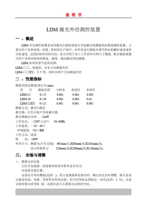
LDM激光外径测控装置一、概述LDM外径测控装置是采用激光扫描原理进行非接触在线测量的高精度测控装置,主要应用于各种电线、电缆、管材的生产线中,对外径进行测量并调节挤出机螺杆速度或牵引机速度,达到控制外径的目的。
也可应用于加工工件的外径和尺寸测量。
配以辅助装置可用于各种回转体的锥度、圆度、轴向跳动等的测量。
LDM系列各型号适用范围:LDM-□□:普通型,在单方向测量外径LDM-□□XY:XY型,同时在两个方向测量外径二、性能指标测量范围及精度(单位为mm):型号测量范围分辨率重复性非线性LDM-250--25 0.001 0.001 0.005LDM-50 0--50 0.001 0.002 0.01LDM-25XY 0--25 0.001 0.001 0.005测量方式:激光扫描法激光器:红色可视半导体激光器激光器输出功率:〈2mW工作电压:~220V±15%50--60Hz工作温度:-10~40℃环境湿度:<85%RH工作方式:连续耗电:<30W外形尺寸:测量头(不含支架)465mm(长)X80mm(宽)X165mm(高)显示控制单元320mm(宽)X280mm(深)X120mm(高)三、安装与调整1、测量头的安装①打开包装箱,按装箱单检查各附件是否齐全。
②选择安装位置:安装在冷却水槽前(见图一),优点是测量和反馈及时,测出误差及时调整。
缺点是显示值是电线、电缆、管材外径的热态值,但可以用标定消除这一误差(见四、2节)。
注意安装时要去掉导轮架,还要注意左右要留出足够的空间。
安装在冷却水槽和吹干机后(见图二),优点是显示结果是成型后的值,缺点是反应速度慢,反馈滞后较大,电线、电缆、管材表面有较厚水膜时会影响测量精度。
③把测量头装到机架上。
④左右移动整体,使被测物对准导轮。
上下移动测量头,使被测物与导轮接触,拧紧支架上的固定螺钉。
如果装在水槽前,要去掉导轮。
正确安装后,测量状态下测量头的位置指示器的中间灯应亮,否则应该调整测量头的上下位置。
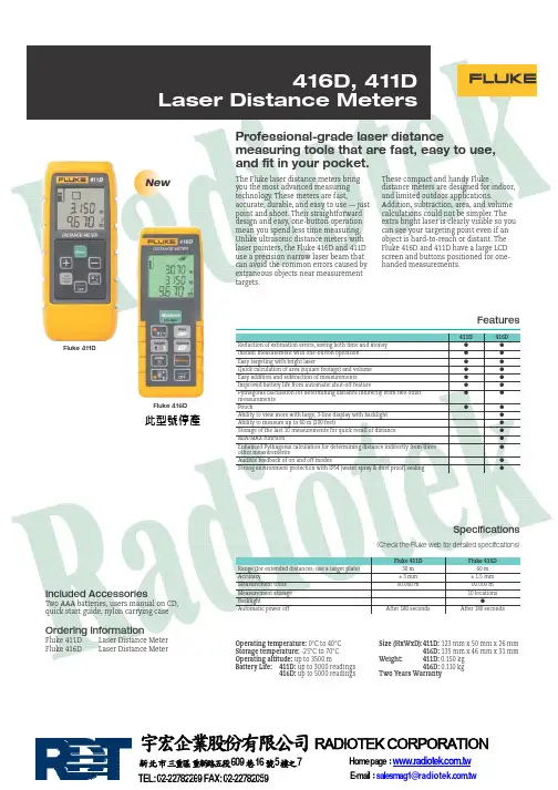
Operating temperature: 0°C to 40°CStorage temperature: -25°C to 70°COperating altitude: up to 3500 mBattery Life:411D: up to 3000 readings416D: up to 5000 readingsSize (HxWxD):411D: 123 mm x 50 mm x 26 mm416D: 135 mm x 46 mm x 31 mmWeight:411D: 0.150 kg416D: 0.110 kgTwo Years WarrantySpecifications(Check the Fluke web for detailed specifications)Included AccessoriesT wo AAA batteries, users manual on CD,quick start guide, nylon carrying caseOrdering InformationFluke 411D Laser Distance MeterFluke 416D Laser Distance MeterThe Fluke laser distance meters bringyou the most advanced measuringtechnology. These meters are fast,accurate, durable, and easy to use — justpoint and shoot. Their straightforwarddesign and easy, one-button operationmean you spend less time measuring.Unlike ultrasonic distance meters withlaser pointers, the Fluke 416D and 411Duse a precision narrow laser beam thatcan avoid the common errors caused byextraneous objects near measurementtargets.These compact and handy Flukedistance meters are designed for indoor,and limited outdoor applications.Addition, subtraction, area, and volumecalculations could not be simpler. Theextra bright laser is clearly visible so youcan see your targeting point even if anobject is hard-to-reach or distant. TheFluke 416D and 411D have a large LCDscreen and buttons positioned for one-handed measurements.FeaturesProfessional-grade laser distancemeasuring tools that are fast, easy to use,and fit in your pocket.Fluke 416DFluke 411DNew此型號停產TEL: 02-22782269 FAX: 02-22782059E-mail:**********************.tw宇宏企業股份有限公司RADIOTEK CORPORATION新北市三重區重新路五段609巷16號5樓之7Home page:。
激光测径仪操作手册LGD-25XY使用仪器前请详细阅读此手册奥美加科技有限公司 AUTO MEASURE GAUGE TECHNOLOGY目 录一、LGD-25XY激光测径仪1、 概述 (2)2、 技术参数 (2)3、 仪器安装 (3)4、 显示 (5)5、 参数设定 (6)6、 反馈控制 (9)7、 通讯 (9)8、 校准 (12)9、 故障列表 (13)二、DPM-XY远端显示控制器1、 简介 (16)2、 技术参数 (16)3、 安装 (16)4、 DPM-XY显示控制器面板及接口信号接线图 (17)5、 DPM-XY显示控制器参数设置 (19)6、 在线调试 (21)一、LGD-25激光测径仪1 概述1.1简介LGD系列激光测径仪是我公司引进国外先进技术开发设计并生产的新一代测径仪。
其采用激光扫描技术,具有测量范围大,精度高,使用寿命长,性能稳定等特点。
1.2适用范围主要用于测量各种材料的直径, 对各种电线、电缆、漆包线、软管和其它线材进行在线测量和控制。
1.3 测试原理:见(图一),由半导体激光器“a”发出激光束,通过电机“c”带动八棱镜“b”高速旋转,将激光器光束扫描通过棱镜“d”转换为平行光通过测试区(GATE),当测试区有被测物“e”时,其会遮挡住部份平行光,并通过聚焦棱镜“f”在光电接收管上转换成低电平;而没有被测物遮挡的平行光则转换为高电平,通过计算低电平的扫描时间,则可计算出被测物在激光束扫描方向的外径值。
(图一) (LGD系列测径仪测量原理)2 技术参数2.1、使用条件供电电源 AC220V±10% 50Hz~60Hz功 耗 ≤15W工作温度 5~45℃相对湿度 ≤80%(无冷凝水)空气中不含腐蚀性气体,油,蒸汽及严重尘埃。
2.2、 主要技术参数型 号 测量范围(mm) 测量精度(mm)LGD-25XY 0.1~20 ±(0.002+0.02%D)注:“D”为被测物的实际值2.3 外围接口RS485通讯接口3 仪器安装3.1 安装位置LGD系列激光测径仪可安装在冷却水槽前,也可以安装在水槽后。

LST系列激光测径仪LST系列激光测径仪使⽤说明书⽬录⼀、概述LST-01/JIC⼿持式激光测径仪采⽤激光扫描⽅式,精度⾼,体积⼩,是⼀款真正适合于便携、移动的直径测量仪器。
该仪器可以从⼀个⽅向对线材进⾏测量,并可以对数据进⾏锁定,以及⼀个可定时关断的背光,以便观察和省电。
⼆、⼯作原理LST-01/JIC激光测径仪⼯作原理图(见图⼀),如图可以看出,测试信息是激光扫过被测物时被挡住部分所形成的阴影信号。
设激光测量区扫描速度为V,被测件挡光时间为T,则被测件直径D=K × V × T ( K为常数)。
电机转速⼀定,即扫描速度V 为常数,通过CPU (微处理器)计算处理,测出挡光时间对应的宽度T,即可得到被测物的直径。
图⼀三、外形尺⼨和技术指标型号:LST-01/JIC整机:长×宽×⾼250 ×69 ×50mm重量:790g连续⼯作时间:8⼩时显⽰器:128 X 64点阵液晶显⽰器激光器:半导体激光器功率:2W电池:7.4V锂电池2200mAH测量范围:0.0200~2.0000mm测量精度:±0.0005mm分辨率:0.0001mm使⽤条件:(1)环境温度:0~40℃(2)相对湿度:80%以下(3)充电电源:交流220V±10% 50HZ(4)空⽓中不含腐蚀性⽓体、油、蒸汽及严重尘埃。
(5)⾃然通风良好。
四、仪器结构介绍1、功能部件包括键盘、电源开关、充电插孔、液晶显⽰器。
见图⼆和图三图⼆图三2、显⽰器介绍如图三所⽰第⼀排是功能指⽰区,在此排的左边显⽰的是当前数据的属性,在它的右边是电量指⽰条。
第⼆排为当前数据显⽰区,它与功能显⽰排的字样相对应,⽐如当功能显⽰排显⽰有“激光测径”时则表⽰当前数据是正在测量的直径值,如果功能显⽰排显⽰的是“常数修改”则显⽰的为本机参数常数值。
另外,当前显⽰数据相应位闪烁时,表⽰此位可以进⾏修改。
6R, 6GPoint and Line Lasers180R, 180GLine Laser LevelsUsers Manual 02/2020LIMITED WARRANTY AND LIMITATION OF LIABILITYThis Fluke product will be free from defects in material and workmanship for three years from the date of purchase. This warranty does not cover fuses, disposable batteries, or damage from accident, neglect, misuse, alteration, contamination, or abnormal conditions of operation or handling. Resellers are not authorized to extend any other warranty on Fluke’s behalf. To obtain service during the warranty period, contact your nearest Fluke authorized service center to obtain return authorization information, then send the product to that Service Center with a description of the problem.THIS WARRANTY IS YOUR ONLY REMEDY. NO OTHER WARRANTIES, SUCH AS FITNESS FOR A PARTICULAR PURPOSE, ARE EXPRESSED OR IMPLIED. FLUKE IS NOT LIABLE FOR ANY SPECIAL, INDIRECT, INCIDENTAL OR CONSEQUENTIAL DAMAGES OR LOSSES, ARISING FROM ANY CAUSE OR THEORY. Since some states or countries do not allow the exclusion or limitation of an implied warranty or of incidental or consequential damages, this limitation of liability may not apply to you.Fluke Corporation Fluke Europe B.V. ООО «Флюк СИАЙЭС»P.O. Box 9090 P.O. Box 1186 125167, г. Москва,Everett, WA 98206 5602 BD Eindhoven Ленинградский проспект дом 37,U.S.A. The Netherlands корпус 9, подъезд 4, 1 этаж11/99Table Of ContentsTitle Page Introduction (1)How to Contact Fluke (1)Safety Information (1)Product Familiarization (3)Features (3)Lasers and Optical Glass (4)Controls (5)Center Point and Accessory Mount (6)Use the Product (7)New Item Alignment (7)New Horizontal or Diagonal Alignment (7)New Vertical Alignment (8)Existing Item Alignment (9)Plumb Marks (6R, 6G Only) (10)New Plumb Marks (10)Existing Item Plumb Check (11)Square Marks (6R, 6G Only) (11)Check Product Accuracy (12)Checking the Horizontal Leveling Accuracy (12)Vertical Laser Accuracy (14)Plumb Accuracy (6R, 6G Only) (15)Accessories (16)Maintenance (16)Clean the Product (16)Batteries (17)RBP5 Rechargeable Battery (17)Housing Glass Insert (18)Specifications (18)6R, 6G, 180R, 180G Users Manual6R, 6G, 180R, 180GIntroduction IntroductionThe 6R, 6G Point and Line Laser Levels and the 180R, and 180G Line Laser Levels (the Product) are batterypowered, self-leveling, professional grade instruments. The 6R and 180R emit solid red line lasers. The 6G and 180G emit solid green line lasers. The 6R and 6G also emit vertical and horizontal point lasers 90 degrees from the Product. Use the Product to lay out reference points to align targets horizontally, vertically, or diagonally.NoteIf the laser beam is difficult to see, use either the SLDR or SLDG Laser Detector to accurately determinethe location of the laser. See the SLDR, SLDG Users Manual.How to Contact FlukeTo contact Fluke, call one of the following telephone numbers:• Technical Support USA: 1-800-44-FLUKE (1-800-443-5853)• Calibration/Repair USA: 1-888-99-FLUKE (1-888-993-5853)• Canada: 1-800-36-FLUKE (1-800-363-5853)• Europe: +31 402-675-200• Japan: +81-3-6714-3114• Singapore: +65-6799-5566• China: +86-400-921-0835• Brazil: +55-11-3530-8901• Anywhere in the world: +1-425-446-5500Or, visit the PLS website at .To view, print, or download the latest manual supplement, visit .Safety InformationA Warning identifies conditions and procedures that are dangerous to the user. A Caution identifies conditions and procedures that can cause damage to the Product or the equipment under test.W* WarningTo prevent eye damage and personal injury:• Read all safety information before you use the Product.• Carefully read all instructions.• Do not alter the Product and use only as specified, or the protection supplied by the Product can be compromised.• Do not use the Product if it operates incorrectly.• Do not use the Product if it is altered or damaged.• Use the Product only as specified or hazardous laser radiation exposure can occur.• Do not look into the laser. Do not point laser directly at persons or animals or indirectly off reflective surfaces.• Do not look directly into the laser with optical tools (for example, binoculars, telescopes, microscopes). Optical tools can focus the laser and be dangerous to the eye.• Do not open the Product. The laser beam is dangerous to eyes.• Batteries contain hazardous chemicals that can cause burns or explode. If exposure to chemicals occurs, clean with water and get medical aid.• Do not disassemble the battery.• Repair the Product before use if the battery leaks.• The battery door must be closed and locked before you operate the Product.• Remove the batteries if the Product is not used for an extended period of time, or if stored in temperatures above50 °C.If the batteries are not removed, battery leakage can damage the Product.• Replace the batteries when the low battery indicator shows to prevent incorrect measurements.• Be sure that the battery polarity is correct to prevent battery leakage.• Use only Fluke approved power adapters to charge the battery.• Do not short the battery terminals together.• Do not disassemble or crush battery cells and battery packs.6R, 6G, 180R, 180GUsers ManualTable 1 is a list of the symbols that can be used on the Product or in this manual.Table 1. SymbolsNoteIn colder climates, the Product needs sufficient time to warm up to achieve the stated accuracymeasurements. Turn on both the horizontal and vertical lasers and wait 3 minutes before you take a measurement. When you move the Product between environments with large differences in ambient temperature, allow for an additional adjustment time.6R, 6G, 180R, 180GProduct Familiarization Product Familiarizationinformation in the manual may apply to your Product.FeaturesUse Table 2 to identify the features and standard accessories of your Product.6R, 6G, 180R, 180GUsers ManualLasers and Optical GlassTable 3 shows the lasers and optical glass.6R, 6G, 180R, 180GControls ControlsTable 4 lists the Controls of the Product.6R, 6G, 180R, 180GUsers ManualCenter Point and Accessory MountFigure 1 shows features that help to layout reference marks. The vertical laser is centered 1.25 in (31.75 mm) from both sides of the Product. To stabilize the Product and view the laser that points down, use the accessory mount to secure the Product to the magnetic L-bracket, the floor stand, or a tripod.31.75 mm31.75 mm1.25 inFigure 1. Center Point and Accessory Mount6R, 6G, 180R, 180GUse the Product Use the ProductUse the Product to layout reference points and to make sure conditions are level and plumb.W* WarningTo prevent eye damage and personal injury, do not look into the optical windows when the Laser indicatorLED shows green.New Item AlignmentNew Horizontal or Diagonal AlignmentNoteTo find diagonal alignment, use the lock feature.To identify new level or grade marks:1. Put the bottom of the Product on a stable surface.2. Turn on the horizontal laser and aim the laser at the target area. See Figure 2.3. Put marks at the level or grade point on the target area.NoteWhen the Product is mounted on a tripod, make sure the tripod head is perfectly level.Errors in marks can result if a tripod is out of level.Figure 2. New Horizontal or Diagonal Alignment76R, 6G, 180R, 180GUsers ManualNew Vertical AlignmentTo identify new marks that are vertically aligned:1. Put the bottom of the Product on a stable surface.2. Turn on the vertical laser and aim the laser at the target area. See Figure3.3. Put marks at the point where the vertical laser intersects the target area.Figure 3. New Vertical Alignment86R, 6G, 180R, 180GExisting Item Alignment Existing Item AlignmentTo determine if an existing item is level or aligned:1. Put the bottom of the Product on a stable surface.2. Aim the horizontal or vertical laser at the target area.3. Measure the distance from the item to the laser at various distances from the Product. See Figure4.If the measurements are the same, the item is level or aligned.Figure 4. Existing Item Alignment96R, 6G, 180R, 180GUsers ManualPlumb Marks (6R, 6G Only)The Product sends plumb marks up and down.New Plumb MarksTo identify new plumb marks on a ceiling or roof:1. Place a cross mark on the point to be transposed.2. Center the down laser over the cross mark. See Figure 5.3. Place a mark at the point where the up laser intersects the target area.To identify new plumb marks on a floor, repeat the steps above but interchange the down and up lasers.NoteUse the floor stand with the Product to increase the sight angle of the vertical down laser.10Existing Item Plumb CheckTo determine if an existing item is plumb:1. Point either the up or down laser at the target area.2. Measure the distance from the item to the laser at various distances from the Product. See Figure 6.If the measurements are the same, the item is plumb.Figure 6. Existing Item Plumb CheckSquare Marks (6R, 6G Only)Use the vertical and horizontal point lasers to create new square marks or to determine if an existing item is square.To layout a new square for a wall or staircase (see Figure 7):1. Mark a vertical line on a wall.2. Center the vertical laser on the line on the wall.3. Place the pendulum target on the floor and align the horizontal point laser with the center vertical line on thependulum target.4. Place a mark on the floor below the point of the pendulum target.5. Move the Product either closer to or farther away from the wall and redo the procedure to make another mark on thefloor.6.Draw a line to connect the two marks. The new line is perpendicular to the wall.112. Direct the laser against wall A and allow the tool to level in. Mark the center of the point where the laser lines crosseach other on the wall (point 1).3. Turn the tool by 180°, allow it to level in and mark the cross point of the laser lines on the opposite wall B (point 2).4. Without turning the tool, position it 6'' from wall B. Switch the tool on and allow it to level in.125. Align the height of the tool (using a tripod or by underlaying, if required) in such a manner that the cross point of thelaser lines is projected against the previously marked point 2 on the wall B.6. Without changing the height, turn around the tool by 180°. Direct it against the wall A in such a manner that thevertical laser line runs through the already marked point 1 . Allow the tool to level in and mark the cross point of the laser lines on the wall A (point 3 ).7. The difference of both marked points 1 and 3 on wall A results in the actual height deviation of the tool alongsidethe lateral axis.On the measuring distance of 2 x 15ft = 30ft, the maximum allowable deviation is: 30ft x ±0.00394in/ft = +/- 1/8” (3 mm) Thus the difference “d” between points 1 and 3 must not exceed 1/8 in (max.).131410.Measure the distance between the center points of the two cross marks.If the distance is ≤3 mm at 10 m (1/8 in at 30 ft), the laser is within calibration accuracy.Figure 8. Vertical Laser Accuracy6R, 6G, 180R, 180GPlumb Accuracy (6R, 6G Only) Plumb Accuracy (6R, 6G Only)To check the accuracy of the plumb:1. Find a site that has a known vertical height X. Put unit on floor stand and place on the floor.2. Place a cross mark at the bottom of the site.13. Center the down point laser on both axes of the cross mark. See Figure 9.1Figure 9. Plumb Accuracy4. Place a cross mark at the point where the up point laser intersects the target area at the top of the site.25. Turn the Product 180 ° on its center.16. Recenter the down point laser on Mark 1 and mark where the up point laser intersects the target area at the top site.37. The distance measured between 2 and 3 is equal to Vd. Divide Vd by two to calculate the difference of error.***************************************************************************************.Table 5.V d 2≤ Y @ XY@Xin.mm ft.m1/320.757.5 2.291/24 1.010.0 3.051/16 1.515.0 4.57156R, 6G, 180R, 180GUsers ManualAccessoriesTable 6 is a list of the accessories available for the Product.Table 6. AccessoriesModel Description PNPLS FS Floor stand5031929PLS MLB Magnetic L-bracket 5031934PLS BP5 BP5 alkaline battery pack 5031952PLS RRT4 Red magnetic reflective target 5022629PLS GRT4 Green magnetic reflective target 5022634PLS-10090 Pendulum layout target, PLS 5 4844979PLS-60573 Canvas pouch 4792193PLS C18 Tool box 4985124PLS UB9 UB9 ceiling/wall bracket 4966636PLS-HGI6R Housing glass insert for 6R 5042456PLS-HGI6G Housing glass insert for 6G 5067785PLS-HGI180R Housing glass insert for 180R 5042463PLS-HGI180G Housing glass insert for 180G 5067797MaintenanceTo maintain the Product, clean the case and optical glass and replace the batteries.W* WarningTo prevent eye damage and personal injury, do not open the Product.The laser beam is dangerous to the eyes.W CautionTo prevent damage to the Product, do not drop the Product. Treat the Product as a calibrated instrument. Clean the ProductClean the case with a damp cloth and a weak soap solution.W CautionTo prevent damage to the Product, do not use abrasives, isopropyl alcohol, or solvents to clean the caseor optic windows.To clean the optical glass, use a pressurized can of air or a dry nitrogen-ion gun, if available, to blow off particulates from the optical surfaces.166R, 6G, 180R, 180GBatteries BatteriesReplace the batteries when the battery indicator LED is red.To install or replace AA batteries (see Figure 10):1. Open the battery compartment.2. Install three AA batteries. Observe the correct polarity.3. Close the battery compartment.Figure 10. Battery ReplacementRBP5 Rechargeable Battery176R, 6G, 180R, 180GUsers ManualHousing Glass InsertIf the optical glass is damaged, replace the housing glass insert. See Table 6 for the part number to order for your Product. To replace the housing glass insert (see Figure 11):1. Remove the five housing glass insert screws. Note the proper placement of each screw because the screws aredifferent sizes.2. Pull out the housing glass insert.3.Replace the insert and screws.Figure 11. Housing Glass Insert ReplacementSpecificationsBatteries 3 x AA Alkaline IEC LR6RBP5 Rechargeable batteryBattery life, continuous use, both lasers, as testedRed≥8 hours≥30 hoursGreen≥3 hours≥12 hours*For RBP5 Rechargeable Battery please refer to the RBP5 Rechargeable Battery Pack Instructions manual. Point laser direction(6R and 6G only)90 ° up, down, left, rightLine fan angleHorizontal ≥180 °Vertical ≥130 °Working rangePoint laser (6R and 6G only) ≤30 m (100 ft)Line laserWithout SLD ≤15 m (50 ft)With SLD 6 m to 60 m (20 ft to 200 ft)Accuracy ≤3 mm at 10 m (≤1/8 in at 30 ft)Laser leveling 4 °186R, 6G, 180R, 180GSpecificationsPoint laser diameter(6R and 6G only) ≤4 mm at 5 mLine laser width ≤2 mm at 5 mTemperatureOperating-10 °C to 50 °C (14 °F to 122 °F)StorageWith batteries -18 °C to 50 °C (-0.4 °F to 122 °F)Without batteries -20 °C to 70 °C (-13 °F to 158 °F)Relative humidity 0 % to 90 % (0 °C to 35 °C) 0 % to 75 % (35 °C to 40 °C) 0 % to 45 % (40 °C to 50 °C)Size (H x W x L) 116 mm x 64 mm x 104 mm (4.6 in x 2.5 in x 4.1 in) Weight ~0.6 kg (1.3 lb)Drop test 1 mSafety IEC 61010-1: Pollution Degree 2Laser IEC 60825-1:2014 Class 2Light source Semiconductor laser diodeMax output power <1 mWWavelengthRed 635 nm ±5 nmGreen 525 nm ±5 nmElectromagnetic Compatibility (EMC)International IEC 61326-1: Basic Electromagnetic Environment CISPR 11: Group 1, Class AGroup 1: Equipment has intentionally generated and/or uses conductively-coupled radio frequency energy that is necessary for the internal function of the equipment itself.Class A: Equipment is suitable for use in all establishments other than domestic and those directly connected to a low-voltage power supply network that supplies buildings used for domestic purposes.There may be potential difficulties in ensuring electromagnetic compatibility in other environments due to conducted and radiated disturbances.Korea (KCC) Class A Equipment (Industrial Broadcasting & Communication Equipment)USA (FCC) 47 CFR 15 subpart B. This product is considered an exempt device per clause 15.103.19。
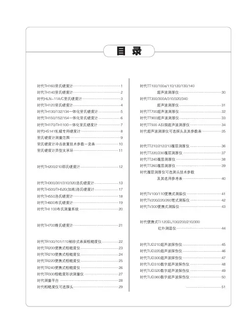
时代仪器 中国名牌北京时代之峰科技有限公司w w w.s h i d a i y i q i.c o m.c n一、时代里氏硬度计系列时代TH160里氏硬度计 (1)时代TH140里氏硬度计 (2)时代HLN-11A/C里氏硬度计 (3)时代TH120里氏硬度计 (4)时代TH130/132/134一体化里氏硬度计 (5)时代TH150/152/154一体化里氏硬度计 (6)时代TH170/TH1100一体化里氏硬度计 (7)时代HS141轧辊专用硬度计 (8)里氏硬度计测量范围 (9)里氏硬度计冲击装置技术参数一览表 (10)里氏硬度计异型支承环 (11)二、时代邵式硬度计系列时代TH200/210邵氏硬度计 (12)三、时代洛氏硬度计系列时代TH300/301/310/320洛氏硬度计 (13)时代TH500/TH520(加高)洛氏硬度计 (17)时代TH550洛氏硬度计 (18)时代TH600布氏硬度计 (19)时代THI 100布氏测量系统 (20)四、时代维氏硬度计时代TH700维氏硬度计 (21)五、时代粗糙度仪系列时代TR100/101/110袖珍式表面粗糙度仪 (22)时代TR200便携式粗糙度仪 (23)时代TR210便携式粗糙度仪 (24)时代TR220便携式粗糙度仪 (25)时代TR240便携式粗糙度仪 (26)时代TR300粗糙度形状测量仪 (27)时代测量平台 (28)时代粗糙度仪可选探头.............................................29六、时代超声波测厚仪系列时代TT100/100a/110/120/130/140超声波测厚仪 (30)时代TT300/300A/310/320/340超声波测厚仪 (31)时代TT700超声波测厚仪 (32)时代TT900超声波测厚仪 (33)时代TT500 A扫描超声波测厚仪 (34)时代超声波测厚仪可选探头及其参数表 (35)七、时代覆层测厚仪系列时代TT210/212/213覆层测厚仪 (36)时代TT220/230覆层测厚仪 (37)时代TT240覆层测厚仪 (38)时代TT260覆层测厚仪 (39)时代覆层测厚仪可选测头技术参数及其选用参考表 (40)八、时代测振仪系列时代TV100/110便携式测振仪 (41)时代TV200/220/260笔式测振仪 (42)时代TV300便携式测振仪 (43)九、时代测温仪系列时代便携式TI 120EL/130/200/210/300红外测温仪 (44)十、时代超声波探伤仪系列时代TUD210超声波探伤仪 (45)时代TUD220超声波探伤仪 (46)时代TUD300超声波探伤仪 (47)时代TUD310数字超声波探伤仪 (48)时代TUD320数字超声波探伤仪 (49)时代TUD360数字超声波探伤仪 (50)十一、时代TA230微型打印机 (51)目录时代仪器 中国名牌功能特点:● 里氏原理、便携测量● 里氏(HL)、布氏(HB)、洛氏(HRC/HRB/HRA)、维氏(HV)、肖氏(HS)等6种硬度值实现一次测量● 可选配7种不同冲击装置并自动识别● 随机现场打印数据和统计直方图● 可通过菜单选择材质,无需设置即可自动识别冲击方向● 限值预设、超差报警● 显示屏直接显示直方图,可接PC机实现测量数据的归档管理与分析● 可存储240-1000组测量值● 全中文菜单、背光显示,方便操作时代TH160里氏硬度计技术参数:测量范围见第9页表1示值误差和示值重复性见第9页表2测量方向任意上下限设置范围(170~960)HLD工作电压 3.7V充电电源6V/500mA充电时间 2.5~4小时工作温度0-40℃通讯接口标准RS232外形尺寸230×90×46.5(mm)重 量约420g(主机)标准配置主机(含热敏打印机)、D型冲击装置、标准里氏硬度块、充电器、小支承环、尼龙刷可选附件7种不同冲击装置(见第10页表3)、各种异型支承环(见第11页表4)、TH160 数据处理软件010-******** 010-********时代仪器中国名牌功能特点:● 里氏原理、便携测量● 里氏(HL)、布氏(HB)、洛氏(HRC/HRB/HRA)、维氏(HV)、肖氏(HS)等6种硬度值实现一次测量● 可选配7种不同冲击装置并自动识别● 随机现场打印数据,可通过菜单选择材质并设置冲击方向● 限值预设、超差报警● 可接PC机实现测量数据的归档管理与分析,可存储48-350组测量值时代TH140里氏硬度计技术参数:测量范围见第9页表1示值误差和示值重复性见第9页表2测量方向任意充电电源12V/DC 600mA充电时间2小时(有过充保护)工作温度0-40℃通讯接口标准RS232外形尺寸270×86×47(mm)重 量530g(含主机和打印机)标准配置主机、打印机、D型冲击装置、标准里氏硬度块、充电器、 小支承环、尼龙刷可选附件7种不同冲击装置(见第10页表3)、各种异型支承环(第11页表4)、 TH140数据处理软件010-******** 010-********时代仪器 中国名牌功能特点:● 里氏原理、便携测量● 里氏(HL)、布氏(HB)、洛氏(HRC/HRB)、维氏(HV)、肖氏(HS)等6种硬度值实现一次测量、直接转换● 可选配7种不同冲击装置并自动识别● 随机现场打印数据●可通过菜单选择材质并设置冲击方向时代HLN-11A/C 里氏硬度计技术参数:测量范围见第9页表1示值误差和示值重复性见第9页表2测量方向任意工作电压 4.7V~6V 充电电源 9V/ 75mA 充电时间8小时工作温度 0-40℃外形尺寸270×86×47(mm)重 量675g(含主机和打印机)标准配置主机、打印机、D型冲击装置、标准里氏硬度块、充电器、小支承环、尼龙刷可选附件7种不同冲击装置(见第10页表3)、各种异型支承环(见第11页表4)010-******** 010-********时代仪器中国名牌功能特点:● 点阵液晶,全中文显示,信息丰富● 菜单式操作,操作简单方便● 一台主机可配备7种不同冲击装置使用,更换时不需校准,自动识别● 可存储48~350组(冲击次数32~1)测量值● 可设置上、下限,超出范围自动报警● 在所有显示界面均可按【帮助】键得到操作提示● 有背光显示,方便暗环境使用● 具有示值软校准功能● 可打印任意份测试结果● 带有RS232接口,多种通讯方式,满足不同用户的个性需求● 可自行更换充电电池时代TH120里氏硬度计技术参数:测量范围(170~960)HLD (17.9-69.5)HRC硬 度 制里氏、肖氏、布氏、洛氏A、洛氏B、洛氏C、维氏测量方向360°示值重复性6HLD(HLD=760时)示值误差±6HLD(HLD=760时)打印纸宽44.5±0.5mm 打印纸卷直径40mm充电时间2~3.5小时充电电源12V/600mmA使用温度0℃~40℃相对湿度≤90%外形尺寸234×88×46mm 重 量0.6kg010-******** 010-********时代仪器 中国名牌功能特点:● 可将HL值转换成布洛维或肖氏硬度值● 直接测量大型或重型的试件● 可测已安装的机械或永久性组装的部件● 金属材料仓库的材料区分● 可测大型工件的狭小空间等● 体积小、重量轻、易于操作● TH130配D型冲击装置● TH132配C型冲击装置,更适合薄、轻以及带表面硬化 层等零部件的测量●TH134配DL型冲击装置,更适合测量深槽槽底或型面(如齿面)零部件的测量时代TH130/132/134系列里氏硬度计技术参数:测量范围见第9页表1示值误差和示值重复性见第9页表2测量方向任意球 头碳化钨充电电源9V/75mA 工作时间持续使用8小时工作温度0~40℃外形尺寸155×24×55(mm)重 量180g标准配置主机(含冲击装置)、标准里氏硬度块、充电器、小支承环、尼龙刷可选附件TA230打印机、异型支承环(见第11页表4)010-******** 010-********时代仪器中国名牌功能特点:● 英文操作界面,背光显示● 可实现六种硬度(HL、HRB、HRC、HB、HV、HS)之间的转换● 可存储最大256个数据● 可与打印机连接● 欠压指示● 具有自动关机功能● TH150配有D型冲击装置● TH152配有C型冲击装置,更适合薄、轻及带表面硬化层等的零部件的测量● TH154配有DL型冲击装置,更适合测量深槽槽底或型面(如齿面)等零部件的测量时代TH150/152/154系列里氏硬度计技术参数:测量范围见第9页表1示值误差和示值重复性见第9页表2测量方向任意球 头碳化钨工作电压3V电 源CR 1/2 AA(1节)工作温度0~40℃外形尺寸213×60×39(mm)重 量约155g(不包括电池)标准配置主机(含冲击装置)、标准里氏硬度块、小支承环、尼龙刷可选附件TA230打印机、异型支承环(见第11页表4)010-******** 010-********时代仪器 中国名牌功能特点:● 可实现六种硬度(HL、HRC、HRB、HRA、HB、HV、HS)之间的相互转换● 带有电压显示和欠压提示,有欠压自动关机功能● 具有示值软校准功能TH170● 全中文菜单式操作、背光显示● 可预先设置硬度值上、下限,超出范围自动报警● 可存储270个平均值,分为9个文件,方便存取● 根据用户的要求,可配备微机软件,功能更加强大,满足质量保证活动和管理的更高要求TH1100● 中/英显示● 存储1组值(当前测试值)● 可预设平均值次数● 造型小巧、操作简便● 可充电锂电池● 适合工件大范围内多处测量部位的快速检验TH170TH1100时代TH170/TH1100里氏硬度计技术参数:TH170TH1100测量范围见第9页表1示值误差和示值重复性见第9页表2冲击装置D 测量方向任 意上下限设置范围(170-960)HLD 无电 源AAA尺寸(7#)1.5V干电池2节充电锂电池工作温度0~40℃通讯接口标准USB2.0无外型尺寸155×55×25(mm)145×35×30(mm)重 量约166g130g标准配置主机(含冲击装置)、干电池2节、标准里氏硬度块、尼龙刷主机(含冲击装置)、充电器、标准里氏硬度块、尼龙刷可选附件异型支承环(见第11页表4)型 号性 能010-******** 010-********时代仪器中国名牌功能特点:● 专业测量轧辊的肖氏硬度值● 里氏(HL )、布氏(HB )、洛氏(HRC/HRB/HRA )、维氏(HV )、 肖氏(HS )等6种硬度值实现一次测量● 可配置7种不同冲击装置并自动识别● 随机现场打印数据● 限值预设、超差报警● 可接PC 机进行测量数据的分析管理● 可存储48-350组测量值● 全中文菜单、背光显示,方便操作时代HS141轧辊专用型硬度计技术参数:测量范围(30~110)HSD 示值误差和示值重复性见第9页表2测量方向任意充电电源12V/DC 600mA 充电时间2小时(有过充保护)工作温度 0~40℃通讯接口标准RS232外型尺寸270×86×47(mm)重 量530g(含主机和打印机)标准配置主机、打印机、D型冲击装置、标准里氏硬度块、充电器、 小支承环、尼龙刷可选附件7种不同冲击装置(见第10页表3)、各种异型支承环(见第11页表4)010-******** 010-********时代仪器 中国名牌里氏硬度计测量范围里氏硬度计测量范围(表1)示值误差和示值重复性(表2)序号冲击装置类型标准里氏硬度块硬度值示值误差示值重复性1D 760±30HLD 530±40HLD ±6HLD ±10HLD 6HLD 10HLD 2DC 760±30HLDC 530±40HLDC ±6HLDC ±10HLDC 6HLDC 10HLDC 3DL 878±30HLDL 736±40HLDL ±12HLDL 12HLDL 4D+15766±30HLD+15544±40HLD+15±12HLD+1512HLD+155G 590±40HLG 500 ±40HLG ±12HLG 12HLG 6E 725±30HLE 508±40HLE ±12HLE 12HLE 7C822±30HLC 590±40HLC±12HLC12HLC材料硬度制冲击装置D/DC D+15C GE DL Steel and cast steel 钢和铸钢HRC 17.9~68.519.3~67.920.0~69.522.4~70.720.6~68.2HRB59.6~99.647.7~99.937.0~99.9HRA 59.1~85.861.7~88.0HB 127~65180~63880~68390~64683~66381~646HV 83~97680~93780~99684~104280~950HS32.2~99.533.3~99.331.8~102.135.8~102.630.6~96.8Steel 锻钢HB 143~650CWT ,ST 合金工具钢HRC 20.4~67.119.8~68.220.7~68.222.6~70.2HV 80~89880~935100~94182~1009Stainless steel不锈钢HRB 46.5~101.7HB 85~655HV85~802GC,IRON 灰铸铁HRC HB 93~33492~326HV NC,IRON 球墨铸铁HRC HB 131~387127~364HV C,ALUM 铸铝合金HB 19~16423~21032~168HRB 23.8~84.622.7~85.023.8~85.5BRASS 铜锌合金HB 40~173HRB 13.5~95.3BRONZE 铜锡(铝)合金HB 60~290COPPER纯铜HB45~315010-******** 010-********时代仪器中国名牌里氏硬度计冲击装置冲击装置技术参数一览表(表3)D DC DL C D+15GE 冲击装置类型D/DC/DL D+15C G E 冲击能量11mJ 11mJ 2.7mJ 90mJ 11mJ 冲击体质量 5.5g/5.5g/7.2g 7.8g 3.0g 20g 5.5g 球头硬度1600HV 1600HV 1600HV 1600HV 5000HV 球头直径3mm 3mm 3mm 5mm 3mm 球头材料碳化钨碳化钨碳化钨碳化钨金刚石冲击装置直径20/20/6mm 20mm 20mm 30mm 20mm 冲击装置长度147/86/202mm 162mm 141mm 255mm 155mm 冲击装置质量75/50/60g 80g 75g 250g 80g 冲击最大硬度940/940/950HV940HV 1000HV 650HV 1200HV 试件表面平均粗糙度(Ra) 1.6μm1.6μm0.4μm6.3μm1.6μm试件最小重量可直接测量>5kg >5kg >1.5kg >15kg >5kg 需稳定支承2~5kg 2~5kg 0.5~1.5kg 5~15kg 2~5kg 需密实耦合0.05~2kg0.05~2kg0.02~0.5kg0.5~5kg0.05~2kg试件最小厚度密实耦合5mm 5mm 1mm 10mm 5mm 硬化层最小厚度0.8mm0.8mm0.2mm1.2mm0.8mm球头压痕尺寸硬度300HV时压痕直径0.54mm 0.54mm 0.38mm 1.03mm 0.54mm 压痕深度24μm 24μm 12μm 53μm 24μm 硬度600HV时压痕直径0.54mm 0.54mm 0.32mm 0.90mm 0.54mm 压痕深度17μm 17μm 8μm 41μm 17μm 硬度800HV时压痕直径0.35mm 0.35mm 0.35mm -0.35mm 压痕深度10μm10μm 7μm -10μm 冲击装置适用范围D型测量通用件;DC型测量内孔或狭小空间内部表面;DL型测量细长窄槽底D+15型测量沟槽或凹入的表面C型测量小的或轻薄的试件及表面硬化层G型测量大的或厚重的试件及表面较粗糙的铸锻件E型适合测量硬度极高的试件010-******** 010-********时代仪器 中国名牌功能特点:当被测表面曲率半径小于30m m (D、DC、D+15、C、E型冲击装置)或小于50mm(G型冲击装置)的试样在测试时,应使用小支承环或异型支承环。
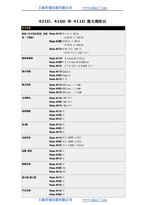
421D 、416D 和 411D 激光测距仪 技术参数距离(对于较长距离对于较长距离,,请使用一个靶板用一个靶板)) Fluke 411D 0.1 m 至 30 m(0.33 ft 至 100 ft ) Fluke 416D 0.05 m 至 60 m(0.16 ft 至 200 ft ) Fluke 421D 0.05 米至 100 米 (0.16 英尺至 330 英尺)测量准确度 Fluke 411D*Fluke 411D* ± 3 mm (0.118 in)Fluke 416D**± 1.5 mm (± 0.059 in)Fluke 421D Fluke 421D ± 1.5 毫米(± 0.059 英寸)激光等级 Fluke 411D Class IIFluke 416D Class IIFluke 421D II 类激光类型 Fluke 411D 635 nm, < 1 mWFluke 416D 635 nm, < 1 mWFluke 421D 635 nm ,< 1 mW自动断电 Fluke 411D 180 秒后Fluke 416D 180 秒后Fluke 421D 180 秒后连续测量 Fluke 411D 是Fluke 416D 是Fluke 421D 是加/减 Fluke 411D 是Fluke 416D 是Fluke 421D 是电池寿命 Fluke 411D 最多 3000 次测量Fluke 416D 最多 5000 次测量Fluke 421D 多达 5,000 个测量值LCD 照明 Fluke 411D 否Fluke 416D 是Fluke 421D 是数据位置 Fluke 411D 否Fluke Fluke 416D 416D 10Fluke 421D 20最小值/最大值 Fluke 411D 否Fluke 416D 是Fluke 421D 是声音反馈 Fluke 411D 否Fluke 416D 是Fluke 421D 是勾股定理功能勾股定理功能((间接测量间接测量))Fluke 411D 简单Fluke 416D 全Fluke 421D 完整防护等级 Fluke 411D IP40Fluke 416D IP54Fluke 421D IP54尺寸 Fluke 411Fluke 411D D 123 mm x 50 mm x 26 mm(4.84 in x 1.97 in x 1.02 in) Fluke 416D 135 mm x 46 mm x 31 mm(5.31 in x 1.81 in x 1.22 in) Fluke 421D 127 毫米 x 52 毫米 x 29 毫米 (5.00 英寸 x 2.06 英寸 x 1.13 英寸)重量 Fluke 411D 150 g (5.29 oz)Fluke 416D 110 g (3.88 oz)Flu Fluke 421D ke 421D 125 克(4.40 盎司)温度范围 Fluke 411D 贮存贮存:: -25 °C 至 70 °C (-13 °F 至 158 °F )工作工作:: 0 °C 至 40 °C (32 °F 至 104 °F ) Fluke 416D 贮存贮存:: -25 °C 至 70 °C (-13 °F 至 158 °F )工作工作:: 0 °C 至 40 °C (32 °F 至 104 °F )Fluke 421D -25 °C 至 70 °C (-13 °F 至 158 °F )0 °C 至 40 °C (32 °F 至 104 °F ) 使用海拔(ISO 9022)(ISO 9022) Fluke 411D 最高 3500 m Fluke 416D 最高 3500 mFluke 421D 高达 3500 米贮存湿度(35 °C 时) Fluke 411D 最高 85 %(24 小时) Fluke 416D 最高 85 %(24 小时)Fluke 421D 最大 85 %,持续 24 小时电池 Fluke 411D AAA (2)Fluke 416D AAA (2)Fluke 4Fluke 421D 21D AAA (2)型号名称描述 Fluke 411D 激光测距仪包括包括::411D 激光测距仪两节 AAA 电池用户手册(位于光盘中) 快速入门指南尼龙便携包两年保修Fluke 416D 激光测距仪包括包括::416D 激光测距仪两节 AAA 电池用户手册(位于光盘中)快速入门指南尼龙便携包两年保修Fluke 421D 激光测距仪包括包括::421D 激光测距仪两节 AAA 电池用户手册(位于光盘中)快速入门指南尼龙便携包两年保修* 在有利条件下(最佳目标表面、室温),最长 10 m (33 ft)。
坚固耐用,一目了然!超凡的图像质量重新定义对焦利用超像素实现起,利用而精准的图像。
焦图像针对指定目标即时获得对焦清晰的图像。
焦为与指定目标之间的距离节省时间nect®快作出决策。
通过两个实用的功能减少现场做笔记的需要:节,无需校准与全新、强大、易于使用的 Fluke Connect SmartView桌面软件。
现代视觉设计直观导航 - 轻松学习,轻松快速地使用简化的工作流程简化的报告流程和优化的报告模板Fluke Connect 云存储购买热像仪时随附 Fluke Connect SmartView® 桌面软件。
下载地址为:/FlukeConnectTI*Fluke Connect SmartView® 分析和报告软件在所有国家 / 地区均有提供,而 Fluke Connect 并非如此。
** 最佳情况和土耳其语100 % 精准对焦 – 每个对象。
近焦和远焦。
MultiSharp™ 多点对焦。
手动对焦MultiSharp TM多点对焦订购信息FLK-Ti480 9Hz 红外热像仪FLK-Ti480 60Hz 红外热像仪随机附件红外热像仪配有:标准红外镜头;交流电源和电池组充电器(含通用交流适配器);两个坚固耐用的锂离子智能电池组;USB 数据线;HDMI 视频数据线;4 GB 微型 SD 卡;结实耐用的硬质携带包;软质运输包以及可调节手带。
提供免费下载:Fluke Connect ® 桌面软件和用户手册。
可选附件FLK-LENS/TELE2 长焦红外镜头(2倍放大) FLK-LENS/4XTELE2 长焦红外镜头(4倍放大) FLK-LENS/WIDE2 广角红外镜头 TI-CAR-CHARGER 车载充电器 FLK-TI-VISOR3 遮阳板TI-TRIPOD3 三脚架安装选件 FLK-TI-BLUETOOTH 蓝牙耳机 FLK-TI-SBP3 智能电池FLK-TI-SBC3B 智能电池充电器射频连接时间(绑定时间)可能需要长达 1分钟。
型号:FLUKE-287000000000000000型号:FLUKE-287000000000000000000000000000000000详细参数000000000000000Fluke 287 真有效值电子记录多用表技术指标准确度0.025 %直流电压50.000 mV, 500.00 mV, 5.0000 V, 50.000量程和分辨率V, 500.00 V, 1000.0V准确度0.4 %(真有效值)交流电压50.000 mV, 500.00 mV, 5.0000 V, 50.000 V,量程和分辨率500.00 V, 1000.0V准确度0,15%500.00 µA, 5000.0 µA, 50.000 mA, 电流DC量程和分辨率400.00 mA, 5.0000 A, 10.000 A准确度0.7 %(真有效值)交流电流500.00 µA, 5000.0 µA, 50.000 mA, 400.00量程和分辨率mA, 5.0000 A, 10.000 A准确度 1.0 %温度(不含探针)-200.0 °C 至1090.0 °C(-328.0 °F 至量程和分辨率1994.0 °F)准确度0.05 %电阻500.00 Ω, 5.0000 kΩ, 50.000 kΩ, 500.00量程和分辨率kΩ, 5.0000 MΩ, 50.00 MΩ, 500.0 MΩ准确度 1.0 %电容量程和分辨率 1.000 nF,10.00 nF 100.0 nF, 1.000 µF,10.00 µF, 100.0 µF, 1000 µF, 10.00 mF,100.00 mF Ω频率准确度0.005% + 1量程和分辨率999.99 kHz附加功能/特性多个屏显是真有效值交流带宽100 kHzDBV/dBm 是电导率50.00nS通断蜂鸣器是温度(°C & °F) -200°C 至1090°C电池/保险丝拆装电池/保险丝峰值250 μS计时时钟是时钟是最小-最大-平均是占空比0.01 % 至99.99 %脉宽0.025 ms, 0.25 ms, 2.5 ms, 1250.0 ms 保持是绝缘光学接口是自动/接触保持是读数存储器是记录到PC是时间间隔/事件记录是记录存储器多达10,000 个读数环境技术指标操作温度-20 °C 至+55 °C 存放温度-40 °C 至+60 °C相对湿度0% 至90%(0 °C 至37 °C)0% 至65%(0 °C 至45 °C)0% 至45%(45 °C 至55 °C)电磁兼容性EMC EN6 1326-1振动随机振动符合MIL-PRF-28800f 标准,2 级仪器撞击 1 米掉落,符合IEC/EN 61010-1 第 2 版安全特性过压保护类别CAT III 1000 V / CAT IV 600 V 安全标准认证CSA, UL, TÜV, CE机械和通用技术指标任意接线端子和接地线之间的最大电压1000V尺寸高x宽x长22.2 cm x 10.2 cm x 6 cm (8.75 in x 4.03 in x 2.38in)重量870.9 g (28 oz)电池寿命最小100 小时,记录模式下200 小时电池类型 6 节AA 电池,NEDA 15A 或IEC LR6型号:FLUKE-87V0000000000000000000000000000000型号:FLUKE-87V0000000000000000000000000000000000详细参数000000000000000 Fluke 80 系列V 数字多用表技术指标直流电压最大电压:1000V准确度:Fluke 83 V: ±(0.1%+1)Fluke 87 V: ±(0.05%+1) 最大分辨率:Fluke 83 V: 100 µVFluke 87 V: 10 µV交流电压最大电压:1000V准确度:Fluke 83 V: ±(0.5%+2)Fluke 87 V: ±(0.7%+2) 真有效值交流带宽Fluke 83 V: 5kHzFluke 87 V: 20kHz**使用低通滤波器;3db @ 1kHz 最大分辨率:0.1 mV直流电流(20 A ,30 秒,最大) 最大电流:10A电流准确度:Fluke 83 V: ±(0.4%+2)Fluke 87 V: ±(0.2%+2) 最大分辨率:Fluke 83 V: 0.01 mAFluke 87 V: 0.01 µA交流电流(20 A ,30 秒,最大)最大电流:10A电流准确度:Fluke 83 V: ±(1.2%+2)Fluke 87 V: ±(1.0%+2) 真有效值最大分辨率:0.1 µA电阻最大电阻:50 MΩ准确度:Fluke 83 V: ±(0.4%+1)Fluke 87 V: ±(0.2%+1) 最大分辨率:0.1Ω电容最大电容9,999 µF 准确度±(1%+2) 最大分辨率0.01 nF频率最大频率200 kHz准确度±(0.005%+1) 最大分辨率0.01 Hz占空比最大占空比准确度±(0.2% /khz +0.1%) 最大分辨率温度测量Fluke 83 V, 87 V/E: -200.0°C - 1090°C-328.0°F - 1994.0°F不包括探头80 BK 温度探头-40.0°C - 260°C-40.0°F - 500°F, 2.2°C 或2%,取较大值电导率最大电导率60.00 nS 准确度±(1.0%+10) 最大分辨率0.01 nS二极管量程 3 V 分辨率 1 mV准确度:± (2 % + 1)占空比量程准确度:± (0.2% /kHz + 0.1 %)之内环境特性操作温度-20°C 至+55°C存放温度-40°C 至+60°C湿度(非凝结)0% - 90% (0°C - 35°C)0% - 70% (35°C - 55°C)操作海拔高度2000 m安全特性过压保护类别EN 61010-1,1000 V CAT III, 600V CAT IV 认证UL、CSA、TÜV 和VDE 认证机械和通用技术指标尺寸201 x 98 x 52 mm (含防护套)重量355 g包括防护套和可折出支架624 g显示数字:6000 字,每秒刷新4次( 87型在高分辨率模式下为19,999 字) 模拟指针32 段,每秒刷新40次频率:19,999 字,,在> 10 Hz时每秒刷新3次保修终身质保电池寿命碱性电池:~400 小时,典型值,无背光撞击 1 米跌落试验,遵循IEC 61010-1:2001振动满足MIL-PRF-28800 对Class 2 设备的要求。
喜利得HILTI PD40 手持式激光测距仪简介喜利得HILTI PD40手持式激光测距仪是一款精确度极高的测量工具。
它使用高端激光技术,能够快速、准确地测量各种距离,并且容易操作,使得使用者能够轻松完成测量任务。
优点1.准确度高:使用高精度激光技术,能够精确测量距离,误差极小。
2.方便快捷:手持式设计,操作简单,使用方便,测量时间短。
3.多功能:除了常规距离测量外,还可进行体积计算、持续测量、间接测量等多种测量方式。
4.耐久性强:外壳采用高强度材料,防水、耐摔、抗干扰,使用寿命长。
使用场景喜利得HILTI PD40手持式激光测距仪广泛应用于建筑、装修、地貌测量、公路设计、市政工程等领域。
在测量过程中,能够快速、准确地获取测量数据,提高工作效率。
使用方法1.首先打开设备,将仪器对准目标物体,按下开/关键,激光将发射并反弹回该物体。
2.然后,仪器会自动计算出距离,并在屏幕上显示测量结果。
3.如果需要进行间接测量,则需要选择仪器的相应测量模式进行测量。
4.最后,使用者可根据需要将结果进行存储或导出。
注意事项1.使用前,请确认设备是否工作正常,测量机构是否清洁。
2.测量时,应将仪器准确对准目标物体,确保测量准确。
3.请谨慎使用,在不同的场合使用不同的测量模式,以确保测量准确度及稳定性。
4.使用后,请注意清洁和存储。
总之,喜利得HILTI PD40手持式激光测距仪是一款精密、高效、方便的测量工具,应用广泛,使用方便,适合各种场合。
在未来,它将会在各种领域中得到更广泛的应用。
FLUKE 416D 激光测距仪详细参数切换到传统表格版
激光测距是光波测距中的一种测距方式,如果光以速度c在空气中传播在A、B两点间往返一次所需时间为t,则A、B两点间距离D可用下列表示。
D=ct/2
式中:D——测站点A、B两点间距离;
c——光在大气中传播的速度;
t——光往返A、B一次所需的时间。
由上式可知,要测量A、B距离实际上是要测量光传播的时间t,根据测量时间方法的不同,激光测距仪通常可分为脉冲式和相位式两种测量形式。
相位式激光测距仪
相位式激光测距仪是用无线电波段的频率,对激光束进行幅度调制并测定调制光往返测线一次所产生的相位延迟,再根据调制光的波长,换算此相位延迟所代表的距离。
即用间接方法测定出光经往返测线所需的时间,如下图所示。
相位式激光测距仪一般应用在精密测距中。
由于其精度高,一般为毫米级,为了有效的反射信号,并使测定的目标限制在与仪器精度相称的某一特定点上,对这种测距仪都配置了被称为合作目标的反射镜。
若调制光角频率为ω,在待测量距离D上往返一次产生的相位延迟为φ,则对应时间t 可表示为:
t=φ/ω
将此关系代入(3-6)式距离D可表示为
D=1/2 ct=1/2 c·φ/ω=c/(4πf) (Nπ+Δφ)
=c/4f (N+ΔN)=U(N+)
式中:φ——信号往返测线一次产生的总的相位延迟。
ω——调制信号的角频率,ω=2πf。
U——单位长度,数值等于1/4调制波长
N——测线所包含调制半波长个数。
Δφ——信号往返测线一次产生相位延迟不足π部分。
ΔN——测线所包含调制波不足半波长的小数部分。
ΔN=φ/ω
在给定调制和标准大气条件下,频率c/(4πf)是一个常数,此时距离的测量变成了测线所包含半波长个数的测量和不足半波长的小数部分的测量即测N或φ,由于近代精密机械加工技术和无线电测相技术的发展,已使φ的测量达到很高的精度。
为了测得不足π的相角φ,可以通过不同的方法来进行测量,通常应用最多的是延迟测相和数字测相,目前短程激光测距仪均采用数字测相原理来求得φ。
由上所述一般情况下相位式激光测距仪使用连续发射带调制信号的激光束,为了获得测距高精度还需配置合作目标,而目前推出的手持式激光测距仪是脉冲式激光测距仪中又一新型测距仪,它不仅体积小、重量轻,还采用数字测相脉冲展宽细分技术,无需合作目标即可达到毫米级精度,测程已经超过100m,且能快速准确地直接显示距离。
是短程精度精密工程测量、房屋建筑面积测量中最新型的长度计量标准器具。
现应用最多的是leica公司生产的DISTO系列手持式激光测距仪。
手持式激光测距仪使用注意事项
DISTO及其他手持式激光测距仪,由于采用激光进行距离测量,而脉冲激光束是能量非常集中的单色光源,所以在使用时不要用眼对准发射口直视,也不要用瞄准望远镜观察光滑反射面,以免伤害人的眼睛。
一定要按仪器说明书中安全操作规范进行测量。
野外测量时不可将仪器发射口直接对准太阳以免烧坏仪器光敏元件。
以上以DISTO仪器为例简要介绍了仪器部分测量功能,不同厂家生产的手持式激光测距仪功能键略有异同,但只要认真阅读使用说明书,就会充分发挥手持式激光测距仪在房屋建筑面积测量和其他精密工程测量中的作用。
激光测距传感器
距传感器在各行各业应用已经非常广泛了,但是一些特殊情况下普通的激光测距传感器仍然束手无策。
近几年来科激光测距传感器从测量频率、测量距离及输出模式等多个方面做了技术革新,现在市场上的激光测距传感器近千种各个行业的需要。
程激光测距传感器就是一款专门为实现远距离的测量任务而研制的,远程激光测距传感器的测量频率在50~2000Hz,达到千米之外。
它有结构紧凑,操作容易,并配置标准的接口工具等优点。
它还具有一路模拟量输出接口、二路数和一路串行接口RS232(RS422可选)。
型应用
钢铁厂和轧钢厂用于过程监控
车定位系统、装卸处理设备的定位系统
人力所不能到达部位的测量,如洞内、管内、特殊容器内等等
辆、船舶的定位监控系统。