VRRP配置实验
- 格式:docx
- 大小:231.23 KB
- 文档页数:5
mstp加vrrp的实验例子(原创实用版)目录1.MSTP 和 VRRP 的概述2.MSTP 加 VRRP 的实验环境搭建3.实验步骤和过程4.实验结果及分析5.实验结论和展望正文一、MSTP 和 VRRP 的概述1.MSTP(Multiple Spanning Tree Protocol):多实例生成树协议,用于在多个 VLAN(虚拟局域网)之间实现生成树保护。
2.VRRP(Virtual Router Redundancy Protocol):虚拟路由器冗余协议,用于提高网络设备的可靠性和冗余性。
二、MSTP 加 VRRP 的实验环境搭建1.设备:两台路由器(Router1 和 Router2),一台交换机(Switch)2.接口:Router1 的接口 G0/0/1 和 G0/0/2 分别连接到 Switch 的接口 1 和 2;Router2 的接口 G0/0/1 和 G0/0/2 分别连接到Switch 的接口 3 和 4。
3.配置:为每个接口分配不同的 VLAN,如 G0/0/1 为 VLAN10,G0/0/2 为 VLAN20。
三、实验步骤和过程1.在 Router1 上配置 MSTP 和 VRRP:a.配置 MSTP:在 Router1 上启用 MSTP,将 G0/0/1 和 G0/0/2 分别配置为 MSTP 的实例 1 和实例 2。
b.配置 VRRP:在 Router1 上启用 VRRP,将 G0/0/1 和 G0/0/2 分别配置为 VRRP 的虚拟路由器 1 和虚拟路由器 2。
2.在 Router2 上配置 MSTP 和 VRRP:a.配置 MSTP:在 Router2 上启用 MSTP,将 G0/0/1 和 G0/0/2 分别配置为 MSTP 的实例 1 和实例 2。
b.配置 VRRP:在 Router2 上启用 VRRP,将 G0/0/1 和 G0/0/2 分别配置为 VRRP 的虚拟路由器 1 和虚拟路由器 2。
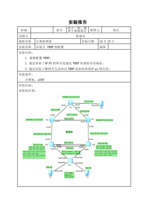
实验报告班级组号两人一组,找班干部要组号联络人组长同组人组成员课程名称计算机网络实验日期10月23日实验名称实验五 VRRP的配置成绩实验目的:1.能够配置VRRP;2. 通过实验了解PC的网关是通过VRRP形成的浮动地址;3. 通过实验了解网关冗余协议VRRP是如何来保护pc网关的。
实验条件:计算机、eNSP实验内容:实验拓扑图:配置思路:在SwitchA和SwitchB上创建VRRP备份组1和VRRP备份组2,在备份组1中,配置SwitchA为Master设备,SwitchB为Backup设备;在备份组2中,配置SwitchB为Master 设备,SwitchA为Backup设备,实现流量的负载均衡。
PC1与PC2的IP配置:SWA的配置(SWB反过来):在SwitchA上创建VRRP备份组1,配置SwitchA的优先级为120,抢占延时为20秒,作为Master设备;在SwitchA上创建VRRP备份组2, SwitchA的优先级为缺省值,作为Backup设备。
在SwitchA上创建VRRP备份组1配置SwitchA的优先级为120,抢占延时为20秒,在SwitchA上创建VRRP备份组2配置SwitchA的优先级为默认,在SwitchB上创建VRRP备份组2,配置SwitchB的优先级为120,抢占延时为20秒,作为Master设备;在SwitchB上创建VRRP备份组1, SwitchB的优先级为缺省值,作为Backup设备。
在SwitchB上创建VRRP备份组2配置SwitchB的优先级为120,抢占延时为20秒,测试:实验总结:通过这次实验我学会了如何配置VRRP协议以及此协议要解决的问题。
通过配置VRRP协议实现流量的负载均衡,保证可靠性。
在配置时要注意IP地址的配置,三层接口的创建等。

一、实验目的
熟悉VRRP协议的使用方式和配置方法
理解VRRP协议的适用场合
二、应用环境
VRRP是一种容错协议,将局域网的多台路由器组织成一台“虚拟”路由器,或称为一个备份组。
在备份组内,总有一台路由器或交换机是活动路由器(Master),它完成“虚拟”路由器的工作,备份组中其它路由器或交换机作为备份路由器(Backup),随时监控Master的活动。
当Master出现故障时,Backup将选举出一个新的Master接替其工作,继续为网段内的各主机提供路由服务,保持网段内主机不间断地与外界保持通信。
三、实验设备
使用Dynamips0.2.7虚拟环境
四、实验拓扑
本实验SW3模拟一台二层HUB或交换机
五、实验要求
1、在交换机SW1和交换机SW2上分别划分基于端口的VLAN:
2、路由器及PC1网络设置
六、实验步骤
1、交换机路由器PC基本配置,网络协议配置,使SW1,SW2,R1互联互通
2、配置VRRP
SW1 配置
SW1(config)#int vlan 1
SW1(config-if)#vrrp 1 ip 192.168.1.254
SW1(config-if)#vrrp 1 priority 254
SW1(config-if)#vrrp 1 authentication text test SW1(config-if)#vrrp 1 preempt
SW2 配置
SW1(config)#int vlan 1。

实验11VRRP配置(V5.1)实验11 VRRP 配置11.1 实验⽬的●熟悉H3C 三层以太⽹交换机的VRRP 功能;●熟悉H3C 三层以太⽹交换机VRRP 的配置。
11.2 实验环境在实验中,我们需要三台H3C S 系列三层以太⽹交换机(本例中为三台S3500系列交换机),⾄少3台PC ,专⽤配置电缆⼀根,⽹线若⼲。
实验组⽹如下图所⽰:Switch_A 的E0/9与Switch_B 的E0/9相连,保证同⼀局域⽹⽤户可以互通,Switch_A 的端⼝0/10、端⼝0/11分别接PCA 、PCB ,Switch_B 的E0/10、E0/11分别接PCC 、PCD ,Switch_A 的E0/17接Switch_C 的E0/1,Switch_B 的E0/17接Switch_C 的E0/9,Switch_C 的E0/17接⼀台PCE 。
Switch_A10.0.0.2PCD:10.0.0.9PCC:10.0.0.8PCB:10.0.0.7PCA:10.0.0.610.0.0.3Switch_CE0/17E0/17E0/17E0/9E0/9~11E0/9~1111.3 实验步骤VRRP 单备份组的实现11.3.1 VRRP单备份组的实现⾸先我们采⽤单备份组进⾏交换机的VRRP功能验证,如实验环境所⽰,⽤三台三层以太⽹交换机组⽹。
1. 配置VLAN和VLAN接⼝分别在Switch_A,Switch_B和Switch_C上配置VLAN和VLAN接⼝,具体配置如下:Switch_A的配置:[Switch_A]vlan 2[Switch_A-vlan2]port Ethernet 0/9 to Ethernet 0/16[Switch_A-vlan2]vlan 3[Switch_A-vlan3]port Ethernet 0/17 to Ethernet 0/24[Switch_A-vlan3]quit[Switch_A]interface Vlan-interface 2[Switch_A-Vlan-interface2]ip address 10.0.0.2 255.255.255.0[Switch_A-Vlan-interface2]quit[Switch_A]interface Vlan-interface 3[Switch_A-Vlan-interface3]ip address 20.0.0.1 255.255.255.0Switch_B的配置:[Switch_B]vlan 2[Switch_B-vlan2]port Ethernet 0/9 to Ethernet 0/16[Switch_B-vlan2]vlan 3[Switch_B-vlan3]port Ethernet 0/17 to Ethernet 0/24[Switch_B-vlan3]quit[Switch_B]interface Vlan-interface 2[Switch_B-Vlan-interface2]ip address 10.0.0.3 255.255.255.0 [Switch_B-Vlan-interface2]quit[Switch_B]interface Vlan-interface 3[Switch_B-Vlan-interface3]ip address 30.0.0.1 255.255.255.0 Switch_C的配置:[Switch_C]vlan 2[Switch_C-vlan2]port Ethernet 0/1 to Ethernet 0/8 [Switch_C-vlan2]vlan 3[Switch_C-vlan3]port Ethernet 0/9 to Ethernet 0/16 [Switch_C-vlan3]vlan 4[Switch_C-vlan4]port Ethernet 0/17 to Ethernet 0/24 [Switch_C-vlan4]quit[Switch_C]interface Vlan-interface 2[Switch_C-Vlan-interface2]ip address 20.0.0.2 255.255.255.0 [Switch_C-Vlan-interface2]quit[Switch_C]interface Vlan-interface 3[Switch_C-Vlan-interface3]ip address 30.0.0.2 255.255.255.0 [Switch_C-Vlan-interface3]quit[Switch_C]interface Vlan-interface 4[Switch_C-Vlan-interface4]ip address 40.0.0.1 255.255.255.0 2. 配置交换机之间的路由Switch_A的配置:[Switch_A]ospf[Switch_A-ospf]area 0[Switch_A-ospf-area-0.0.0.0]network 10.0.0.0 0.0.0.255 [Switch_A-ospf-area-0.0.0.0]network 20.0.0.0 0.0.0.255 Switch_B的配置:[Switch_B]ospf[Switch_B-ospf]area 0[Switch_B-ospf-area-0.0.0.0]network 10.0.0.0 0.0.0.255 [Switch_B-ospf-area-0.0.0.0]network 30.0.0.0 0.0.0.255 Switch_C的配置:[Switch_C]ospf[Switch_C-ospf]area 0[Switch_C-ospf-area-0.0.0.0]network 20.0.0.0 0.0.0.255[Switch_C-ospf-area-0.0.0.0]network 30.0.0.0 0.0.0.255[Switch_C-ospf-area-0.0.0.0]network 40.0.0.0 0.0.0.255完成上述配置之后,验证各交换机之间的路由是否正常。

vrrp配置实验心得
在进行 VRRP(虚拟路由冗余协议)配置实验后,我得出了一些心得体会。
首先,VRRP协议是用于提供冗余路由功能的协议,通过配置虚拟路由器,可以实现路由器的冗余备份,提高网络的可靠性和稳定性。
在实验中,我学会了如何配置VRRP,包括设置虚拟路由器的优先级、虚拟IP地址以及跟踪对象等参数。
此外,我还了解到VRRP协议的工作原理和状态转换过程,以及如何进行故障排除和监控。
通过实验,我深刻体会到了VRRP协议在网络中的重要性,以及如何正确地配置和管理VRRP,以确保网络的高可用性和稳定性。
总的来说,VRRP配置实验让我对网络冗余和高可用性有了更深入的理解,也提升了我的网络配置和故障处理能力。
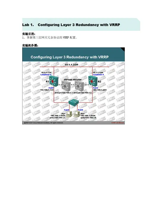
Lab 1.Configuring Layer 3 Redundancy with VRRP
实验目的:
1、掌握第三层网关冗余协议的VRRP配置。
实验拓扑图:
实验步骤及要求:
1、本实验可以使用三层交换机完成,也可以使用路由器完成,在使用路由器时需要注意IOS的版本,确认支持HSRP协议。
2、配置PC1与PC2路由器,将其模拟成主机,配置如下:
3、首先在PC1和PC2上使用ping和traceroute命令,确认网络是否可达:
4、将R1路由器的FA0/0接口,置为down状态:
5、再次在R1和R2上使用ping和traceroute命令测试:
6、虽然有两台路由器都可以到达目标网络,但是默认情况下,并没有充分利用冗余设备,因此当网络单点出错时,必然会引起部分用户无法访问网络。
7、为了解决这一问题,在R1和R2上配置VRRP协议,配置如下:
8、通过查看两台路由器的VRRP组汇总信息,确认不同路由器的组身份:
9、再次把R1路由器的Fa0/0接口置为DOWN状态,两台路由器将会出现如下信息:
10、再次在R1和R2上使用ping和traceroute确认:
11、由于在网络中启用了两个不同的VRRP组,所以最大限度上确保了网络冗余。
同时为了更好的观察VRRP的工作过程,建议在R1和R2路由器上使用扩展的PING 命令持续向目标网络发送数据包。
同时在R1和R2路由器使用如下命令进行调试,具体不再列出:
12、实验完成。
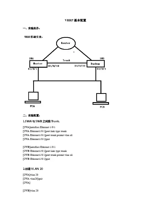
VRRP基本配置一、实验拓扑:二、实验配置:1.SWA与SWB之间跑Trunk.[SWA]interface Ethernet 1/0/1[SWA-Ethernet1/0/1]port link-type trunk[SWA-Ethernet1/0/1]port trunk permit vlan all[SWA-Ethernet1/0/1]quit[SWB]interface Ethernet 1/0/1[SWB-Ethernet1/0/1]port link-type trunk[SWB-Ethernet1/0/1]port trunk permit vlan all[SWB-Ethernet1/0/1]quit2.创建VLAN 20[SWA]vlan 20[SWA-vlan20]quit[SWA][SWB]vlan 20[SWB-vlan20]quit[SWB]3.跑VRRP[SWA]interface Vlan-interface 20[SWA-Vlan-interface20]ip address 192.168.2.101 255.255.255.0[SWA-Vlan-interface20]vrrp vrid 1 virtual-ip 192.168.2.100[SWA-Vlan-interface20]vrrp vrid 1 priority 120[SWA-Vlan-interface20]vrrp vrid 1 preempt-mode[SWA-Vlan-interface20]vrrp vrid 1 timer advertise 30[SWA-Vlan-interface20]vrrp vrid 1 authentication-mode md5 cisco[SWA-Vlan-interface20]quit[SWA][SWB]interface Vlan-interface 20[SWB-Vlan-interface20]ip address 192.168.2.102 255.255.255.0[SWB-Vlan-interface20]vrrp vrid 1 virtual-ip 192.168.2.100[SWB-Vlan-interface20]vrrp vrid 1 priority 100[SWB-Vlan-interface20]vrrp vrid 1 preempt-mode[SWB-Vlan-interface20]vrrp vrid 1 timer advertise 30[SWB-Vlan-interface20]vrrp vrid 1 authentication-mode md5 cisco[SWB-Vlan-interface20]quit[SWB]%Apr 2 00:11:47:154 2000 SWA L2INF/5/VLANIF LINK STATUS CHANGE:- 1 -Vlan-interface20 is UP%Apr 2 00:11:47:265 2000 SWA VRRP/5/MasterChange:- 1 -Vlan-interface20 | Virtual Router 1 : INITIALIZE --> BACKUP reason: Received interface event%Apr 2 00:11:47:455 2000 SWA IFNET/5/UPDOWN:- 1 -Line protocol on the interfaceVlan-interface20 is UP%Apr 2 00:13:17:144 2000 SWA VRRP/5/MasterChange:- 1 -Vlan-interface20 | Virtual Router 1 : BACKUP --> MASTER reason: Fail receiving VRRP advertisement message in 3 times Advertisement_Interval[SWA]dis vrrp verboseRun Method : VIRTUAL-MACVirtual Ip Ping : DisableInterface : Vlan-interface20VRID : 1 Adver. Timer : 30Admin Status : UP State : MasterConfig Pri : 120 Run Pri : 120Preempt Mode : YES Delay Time : 0Auth Type : MD5 Key :5W97B'/VOV+Q=^Q`MAF4<1!!Virtual IP : 192.168.2.100Virtual MAC : 0000-5e00-0101Master IP : 192.168.2.101[SWA][SWB]display vrrp verboseRun Method : VIRTUAL-MACVirtual Ip Ping : DisableInterface : Vlan-interface20VRID : 1 Adver. Timer : 30Admin Status : UP State : BackupConfig Pri : 100 Run Pri : 100Preempt Mode : YES Delay Time : 0Auth Type : MD5 Key : 5W97B'/VOV+Q=^Q`MAF4<1!!Virtual IP : 192.168.2.100Master IP : 192.168.2.101%Apr 2 00:12:39:444 2000 SWB L2INF/5/VLANIF LINK STATUS CHANGE:- 1 -Vlan-interface20 is UP%Apr 2 00:12:39:555 2000 SWB VRRP/5/MasterChange:- 1 -Vlan-interface20 | Virtual Router 1 : INITIALIZE --> BACKUP reason: Received interface event%Apr 2 00:12:39:745 2000 SWB IFNET/5/UPDOWN:- 1 -Line protocol on the interface Vlan-interface20 is UP三、实验总结:。
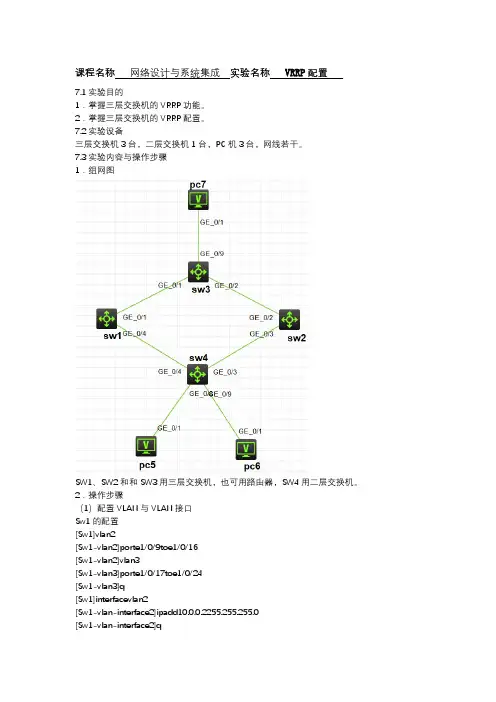
课程名称网络设计与系统集成实验名称VRRP配置7.1实验目的1.掌握三层交换机的VRRP功能。
2.掌握三层交换机的VRRP配置。
7.2实验设备三层交换机3台,二层交换机1台,PC机3台,网线若干。
7.3实验内容与操作步骤1.组网图SW1、SW2和和SW3用三层交换机,也可用路由器,SW4用二层交换机。
2.操作步骤(1)配置VLAN与VLAN接口Sw1的配置[Sw1]vlan2[Sw1-vlan2]porte1/0/9toe1/0/16[Sw1-vlan2]vlan3[Sw1-vlan3]porte1/0/17toe1/0/24[Sw1-vlan3]q[Sw1]interfacevlan2[Sw1-vlan-interface2]ipadd10.0.0.2255.255.255.0[Sw1-vlan-interface2]q[Sw1]interfacevlan3[Sw1-vlan-interface3]ipadd20.0.0.1255.255.255.0 Sw2的配置[Sw2]vlan2[Sw2-vlan2]porte1/0/9toe1/0/16[Sw2-vlan2]vlan3[Sw2-vlan3]porte1/0/17toe1/0/24[Sw2-vlan3]q[Sw2]interfacevlan2[Sw2-vlan-interface2]ipadd10.0.0.3255.255.255.0 [Sw2-vlan-interface2]q[Sw2]interfacevlan3[Sw2-vlan-interface3]ipadd30.0.0.1255.255.255.0 Sw3的配置[Sw3]vlan2[Sw3-vlan2]porte1/0/1toe1/0/8[Sw3-vlan2]vlan3[Sw3-vlan3]porte1/0/9toe1/0/16[Sw3-vlan3]vlan416[Sw3-vlan4]porte1/0/17toe1/0/24[Sw3-vlan4]q[Sw3]interfacevlan2[Sw3-vlan-interface2]ipadd20.0.0.2255.255.255.0 [Sw3-vlan-interface2]q[Sw3]interfacevlan3[Sw3-vlan-interface3]ipadd30.0.0.2255.255.255.0 [Sw3-vlan-interface3]q[Sw3]interfacevlan4[Sw3-vlan-interface3]ipadd40.0.0.1255.255.255.0 (2)配置交换机之间的路由Sw1的配置[Sw1]rip[Sw1-rip-1]network10.0.0.0[Sw1-rip-1]network20.0.0.0Sw2的配置[Sw2]rip[Sw2-rip-1]network10.0.0.0[Sw2-rip-1]network30.0.0.0Sw3的配置[Sw3]rip[Sw3-rip-1]network30.0.0.0[Sw3-rip-1]network30.0.0.0[Sw3-rip-1]network40.0.0.0配置完成后,验证个交换机之间路由的是否正常。
Lab 1.Configuring Layer 3 Redundancy with VRRP
实验目的:
1、掌握第三层网关冗余协议的VRRP配置。
实验拓扑图:
实验步骤及要求:
1、本实验可以使用三层交换机完成,也可以使用路由器完成,在使用路由器时需要注意IOS的版本,确认支持HSRP协议。
2、配置PC1与PC2路由器,将其模拟成主机,配置如下:
3、首先在PC1和PC2上使用ping和traceroute命令,确认网络是否可达:
4、将R1路由器的FA0/0接口,置为down状态:
5、再次在R1和R2上使用ping和traceroute命令测试:
6、虽然有两台路由器都可以到达目标网络,但是默认情况下,并没有充分利用冗余设备,因此当网络单点出错时,必然会引起部分用户无法访问网络。
7、为了解决这一问题,在R1和R2上配置VRRP协议,配置如下:
8、通过查看两台路由器的VRRP组汇总信息,确认不同路由器的组身份:
9、再次把R1路由器的Fa0/0接口置为DOWN状态,两台路由器将会出现如下信息:
10、再次在R1和R2上使用ping和traceroute确认:
11、由于在网络中启用了两个不同的VRRP组,所以最大限度上确保了网络冗余。
同时为了更好的观察VRRP的工作过程,建议在R1和R2路由器上使用扩展的PING 命令持续向目标网络发送数据包。
同时在R1和R2路由器使用如下命令进行调试,具体不再列出:
12、实验完成。
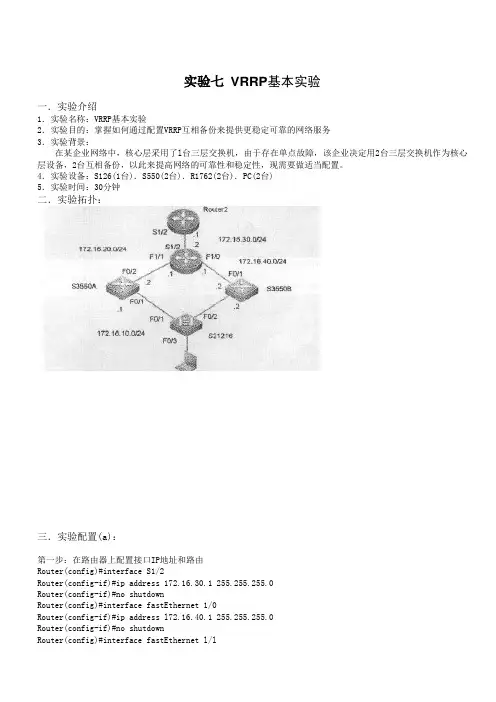
实验七VRRP基本实验一.实验介绍1.实验名称:VRRP基本实验2.实验目的:掌握如何通过配置VRRP互相备份来提供更稳定可靠的网络服务3.实验背景:在某企业网络中,核心层采用了l台三层交换机,由于存在单点故障,该企业决定用2台三层交换机作为核心层设备,2台互相备份,以此来提高网络的可靠性和稳定性,现需要做适当配置。
4.实验设备:S126(1台).S550(2台).R1762(2台).PC(2台)5.实验时间:30分钟二.实验拓扑:三.实验配置(a):第一步:在路由器上配置接口IP地址和路由Router(config)#interface S1/2Router(config-if)#ip address 172.16.30.1 255.255.255.0Router(config-if)#no shutdownRouter(config)#interface fastEthernet 1/0Router(config-if)#ip address l72.16.40.1 255.255.255.0Router(config-if)#no shutdownRouter(config)#interface fastEthernet l/lRouter(config-if)#ip address 172.16.20.1 255.255.255.0Router(config-if)#no shutdownRouter(config)#router ripRouter(config-router)#network 172.16.0.0Router2(config)#intefface serial 1/2Router2(config-if)#ip address 172.16.30.2 255.255.255.0Router2(config-if)#no shutdownRouter2(config)#router ripRouter2(config-rotuer)#network 172.16.0.0第二步:在S3550A上配置VRRP备份组及路由S3550A(config)#interface fastEthernet 0/1S3550A(config-if)#no switchport !设置端口 F0/1为路由口S3550A(config-if)#ip add 172.16.10.1 255.255.255.0S3550A (config-if)#standby l ip 172.16.10.1 !创建VRRP备份组l,并配置组IP地址S3550A (config-if)#standby 1 preempt !设置VRRP各份组处于抢占模式S3550A(config)#interface fastEthernet 0/2S3550A(config-if)#no switchport !设置端口F0/2 为路由口S3550A(config-if)#ip address 172.16.20.2 255.255.255.0S3550A(config-if)#no shutdownS3550A(config)#router ripS3550A(config-router)#network 172.16.0.0第三步:在S3550B上配置VRRP备份组S3550B(config)#interface fastEthernet 0/2S3550B(config-if)#no SwitchportS3550B(config-if)#ip address 172.16.10.2 255.255.255.0S3550B(config-if)#no shutdownS3550B(config-if)#Standby 1 ip 172.16.10.1S3550B(config-if)#standby 1 preemptS3550B(config)#interface fastEthernet 0/1S3550B(config-if)#no switchportS3550B(config-if)#ip address 172.16.40.2 255.255.255.0S3550B(config-if)#no shutS3550B(config)#router ripS3550B(config-router)#network 172.16.0.0【注意事项】· 2台S550-24交换机也可用路由器代替:在路由器上定义VRRP备份组时,用vrrp命令取代standby命令。
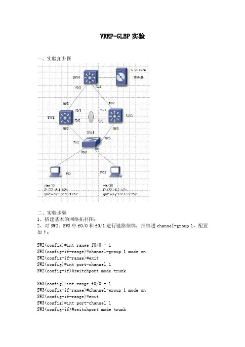
VRRP-GLBP实验一、实验拓扑图二、实验步骤1、搭建基本的网络拓扑图;2、对SW2、SW3中f0/0和f0/1进行链路捆绑,捆绑进channel-group 1,配置如下:SW2(config)#int range f0/0 - 1SW2(config-if-range)#channel-group 1 mode onSW2(config-if-range)#exitSW2(config)#int port-channel 1SW2(config-if)#switchport mode trunkSW3(config)#int range f0/0 - 1SW3(config-if-range)#channel-group 1 mode onSW2(config-if-range)#exitSW3(config)#int port-channel 1SW3(config-if)#switchport mode trunk3、调整生成树,使SW2成为vlan10的根桥,SW3成为vlan20的根桥,配置如下:SW2(config)#spanning-tree vlan 10 priority 4096SW3(config)#spanning-tree vlan 10 priority 4096在SW1查看生成树信息如下:VRRP实现:1、对于vlan10,SW2作为VRRP的master、SW3作为backup;对于vlan20,SW3作为VRRP的master、SW2作为backup,配置如下:SW2(config)#int vlan 10SW2(config-if)#ip address 172.16.1.254 255.255.255.0SW2(config-if)#no shutSW2(config-if)#vrrp 10 ip 172.16.1.252SW2(config-if)#vrrp 10 priority 150SW2(config)#int vlan 20SW2(config-if)#ip address 172.16.2.254 255.255.255.0SW2(config-if)#no shutSW2(config-if)#vrrp 20 ip 172.16.2.252SW3(config)#int vlan 10SW3(config-if)#ip address 172.16.1.253 255.255.255.0 SW3(config-if)#no shutSW3(config-if)#vrrp 10 ip 172.16.1.252SW3(config)#int vlan 20SW3(config-if)#ip address 172.16.2.253 255.255.255.0 SW3(config-if)#no shutSW3(config-if)#vrrp 20 ip 172.16.2.252SW3(config-if)#vrrp 20 priority 150查看SW2的VRRP信息:查看SW3的VRRP信息:2、SW2、SW3、SW4之间起eigrp协议,SW4起一个回环口6.6.6.6/24作为服务器。
实验五配置VRRP单备份组【实验名称】配置VRRP单备份组【实验目的】配置VRRP单备份组实现VRRP的冗余备份模式【背景描述】某集团公司总部在北京,分公司在上海,分公司和总部之间一条线路连接,在总部和分公司间运行OSPF。
在使用网络过程中经常出现由于线路故障导致网络中断的情况,为了实现分公司与总公司之间的高可用性,所以希望在分公司的网络中通过配置VRRP,实现通过两条线连接到总公司,两条线路互为备份。
【需求分析】要解决分公司采用单条链路接入到总部容易出现单点故障的问题,可以采用多条线路接入总部网络,同时在分公司的出口路由器上运行VRRP,使两条线路互为备份,出现故障时自动切换。
【实验拓扑】【实验设备】路由器 3台 交换机 1台 PC机 2台【预备知识】路由器基本配置知识、OSPF基本配置、VRRP工作原理。
【实验原理】VRRP技术是解决网络中主机配置单网关容易出现单点故障问题的一项技术,通过将多台路由器配置到一个VRRP组中,每一个VRRP组虚拟出一台虚拟路由器,作为网络中主机的网关。
一个VRRP组中,所有真实路由器选举出来一台优先级最高的路由器作为主路由器。
虚拟路由器的转发工作由主路器承担。
当主路由器因故障宕机时,备份路由器成为主路由器,承担虚拟路由器的转发工作,从而保证网络的稳定性。
【实验步骤】第一步:在路由器上配置IP地址RA#config terminalRA(config)#interface serial 1/2RA(config-if)#ip address 200.1.1.1 255.255.255.252RA(config-if)#exitRA(config)#interface FastEthernet 1/0RA(config-if)#ip address 12.1.1.1 255.255.255.0RA(config-if)#exitRB#config terminalRB(config)#interface FasEthernet 1/0RB(config-if)#ip address 12.1.1.2 255.255.255.0RB(config if)#exitRB(config)#interface FastEthernet 1/1RB(config-if)#ip address 65.1.1.1 255.255.255.252RB(config-if)#exitRC#config terminalRC(config)#interface serial 1/2RC(config-if)#ip address 200.1.1.2 255.255.255.252RC(config-if)#clock rate 64000RC(config-if)#exitRC(config)#interface FastEthernet 1/1RC(config-if)#ip address 65.1.1.2 255.255.255.252RC(cofnig-if)#exitRC(config)#interface FastEthernet 1/0RC(config-if)#ip address172.16.1.1 255.255.255.0RC(config)#exit第二步:配置OSPFRA(config)#router sopfRA(config-reouter)#network 12.1.1.0 0.0.0.255 area 0.0.0.0RA(config-reouter)#network 200.1.1.0 0.0.0.3 area 0.0.0.0RB(cofnig)#router ospfRB(config-router)#network 12.1.1.0 0.0.0.255 area 0.0.0.0RB(cofnig-router)#network 65.1.1.0 0.0.0.3 area 0.0.0.0RC(config)#router ospfRC(config-router)#network 65.1.1.0 0.0.0.3 area 0.0.0.0RC(config-router)#network 172.16.1.0 0.0.0.0 area 0.0.0.0RC(config-router)#network 200.1.1.0 0.0.0.3 area 0.0.0.0第三步:配置VRRPRA(config)#interface FasEthernet 1/0RA(config-if)#vrrp 32 ip 12.1.1.254RA(config-if)#vrrp 32 priority 120!将RA在VRRP组32中的优先级配置为较高的的120,从而能够成为Master路由器RA(config-if)#vrrp 32track serial 1/2 30!将RA在VRRP组32中对端口serial1/2进行监控,当监控的端口状态为DOWN时,路由器优先级降低30RB(config)#interface FastEthernet 1/0RB(config-if)#vrrp 32 ip 12.1.1.254第四步:验证测试使用show vrrp brief来验证配置。
实验拓扑:实验需求:实验设备:两台AR2220,两台S5700,一台S3700,两台PC1.客户一属于vlan10,客户二属于vlan20;2.汇聚层运行VRRP进行备份冗余,汇聚交换机间采用LACP进行链路捆绑;二层生成树采用MSTP;3.核心与汇聚之间起OSPF;4.广域网链路采用PPP封装;5.要求全网可达,vlan10 流量走左边且在LSW1挂掉后切换到LSW2,vlan20流量走右边且在LSW2挂掉后切换到LSW1;6.测试流量走向,分析Root与Master不一致情况下流量走向。
思路:1、规划IP2、划分好access及trunk口3、链路捆绑display eth-trunk 1 display int eth-trunk 14、配置vrrpnterface Vlanif10vrrp vrid 1 virtual-ip 10.1.1.254vrrp vrid 1 priority 120vrrp vrid 1 preempt-mode timer delay 205、配置mstp生成树stp region-configurationregion-name g1instance 1 vlan 10instance 2 vlan 20active region-configurationstp enablestp instance 1 root primarystp instance 2 root secondary6、核心与汇聚之间起OSPF=============================================配置:AR1:interface Serial4/0/0ip address 10.1.5.1 255.255.255.0ip route-static 0.0.0.0 0.0.0.0 10.1.5.2--------------------------------------------------------------------------------AR2:interface Serial4/0/0ip address 10.1.5.2 255.255.255.0#interface GigabitEthernet0/0/1ip address 10.1.3.2 255.255.255.0#interface GigabitEthernet0/0/2ip address 10.1.4.2 255.255.255.0#ospf 1 router-id 1.1.1.1default-route-advertise---------------下发默认路由#area 0.0.0.0network 10.1.3.0 0.0.0.255network 10.1.4.0 0.0.0.255#ip route-static 0.0.0.0 0.0.0.0 10.1.5.1========================================================== LSW1:vlan batch 10 20 30#stp instance 1 root primary-------------------配置mstp生成树stp instance 2 root secondary#stp region-configurationregion-name g1instance 1 vlan 10instance 2 vlan 20active region-configuration#interface Vlanif10---------------------------配置vrrpip address 10.1.1.253 255.255.255.0vrrp vrid 1 virtual-ip 10.1.1.254vrrp vrid 1 priority 120vrrp vrid 1 preempt-mode timer delay 20#interface Vlanif20ip address 10.1.2.253 255.255.255.0vrrp vrid 2 virtual-ip 10.1.2.254vrrp vrid 2 preempt-mode timer delay 20#interface Vlanif30ip address 10.1.3.1 255.255.255.0#interface Eth-Trunk1--------------------------创建Etherchannel口port link-type trunkport trunk allow-pass vlan 10 20-----------允许vlan10 20mode lacp-static-----------------------------启用lacp#interface GigabitEthernet0/0/1------------华为交换机不能直接配置IP,需要关联。
华为实训14-2VRRP配置第1节实验技术原理上一章实例所学的是WAN链路备份。
特征是Standby的使用。
那么链路备份还有LAN链路备份和路由协议备份。
这两项内容我们此前都学习过。
LAN链路备份,在学习交换机配置时候,可以使用二层交换机支持的STP 协议实现;路由协议备份就更熟悉不过了,前面我们学习了动态路由协议RIP 和OSPF,动态路由协议的特点就是能够自动发现路由,生成路由表。
动态路由协议的特性决定了它可以用于链路备份。
在此不再累赘。
下面我们还是主要学习一下VRRP。
一、VRRP概述如图1-1所示,通常,同一网段内的所有主机都设置一条相同的以网关为下一跳的缺省路由。
主机发往其他网段的报文将通过缺省路由发往网关,再由网关进行转发,从而实现主机与外部网络的通信。
当网关发生故障时,本网段内所有以网关为缺省路由的主机将无法与外部网络通信。
缺省路由为用户的配置操作提供了方便,但是对缺省网关设备提出了很高的稳定性要求。
增加出口网关是提高系统可靠性的常见方法,此时如何在多个出口之间进行选路就成为需要解决的问题。
VRRP(Virtual Router Redundancy Protocol,虚拟路由器冗余协议)将可以承担网关功能的路由器加入到备份组中,形成一台虚拟路由器,由VRRP的选举机制决定哪台路由器承担转发任务,局域网内的主机只需将虚拟路由器配置为缺省网关。
VRRP是一种容错协议,在提高可靠性的同时,简化了主机的配置。
在具有多播或广播能力的局域网(如以太网)中,借助VRRP能在某台设备出现故障时仍然提供高可靠的缺省链路,有效避免单一链路发生故障后网络中断的问题,而无需修改动态路由协议、路由发现协议等配置信息。
VRRP协议的实现有VRRPv2和VRRPv3两个版本。
其中,VRRPv2基于IPv4,VRRPv3基于IPv6。
两个版本的VRRP在功能实现上并没有区别,只是在IPv4设备上和IPv6设备上使用的命令不同。
dhcp+mstp+vrrp实验一、VLAN配置SW3配置sy sw3un in envlan batch 10 20 30 40interface g0/0/3port link-type accessport default vlan 10qinterface g0/0/4port link-type accessport default vlan 20SW4配置sy sw4un in envlan batch 10 20 30 40interface g0/0/3port link-type accessport default vlan 30qinterface g0/0/4port link-type accessport default vlan 40q二、Trunk配置SW3配置interface g0/0/1port link-type trunkport trunk allow-pass vlan 10 20interface g0/0/2port link-type trunkport trunk allow-pass vlan 10 20SW4配置interface g0/0/1port link-type trunkport trunk allow-pass vlan 30 40qinterface g0/0/2port link-type trunkport trunk allow-pass vlan 30 40q三、链路聚合SW1和SW2之间我们用两根网线,做成链路聚合。
SW1配置[hxsw1]int Eth-Trunk 1[hxsw1-Eth-Trunk1]mode lacp-static[hxsw1-Eth-Trunk1]trunkport g0/0/2[hxsw1-Eth-Trunk1]trunkport g0/0/3SW2配置[hxsw2]int Eth-Trunk 1[hxsw2-Eth-Trunk1]mode lacp-static[hxsw2-Eth-Trunk1]trunkport g0/0/1[hxsw2-Eth-Trunk1]trunkport g0/0/3[hxsw2-Eth-Trunk1]配置trunk,允许所有vlan通过sw1[sw1]int Eth-Trunk 1[sw1-Eth-Trunk1]port link-type trunk[sw1-Eth-Trunk1]port trunk allow-pass vlan 10 20 30 40Sw2[sw2]int Eth-Trunk 1[sw2-Eth-Trunk1]port link-type trunk[sw2-Eth-Trunk1]port trunk allow-pass vlan 10 20 30 40四、MSTP配置公共配置以下步骤必须在所有的有冗余的交换机上做,stp region-configurationregion-name pokes01 #域名pokes01revision-level 1 #修订好统一为1instance 1 vlan 10 20 #将vlan10/20映射到实例1里面instance 2 vlan 30 40active region-configuration #激活才能生效qSW1配置[sw1]stp instance 1 root primary #将SW1作为实例1的根桥[sw1]stp instance 2 root secondary #将SW1作为实例2的备份根桥SW2配置[sw2]stp instance 1 root secondary[sw2]stp instance 2 root primary五、VRRP配置sw1配置interface Vlanif10ip address 192.168.10.253 255.255.255.0 vrrp vrid 10 virtual-ip 192.168.10.1vrrp vrid 10 priority 120interface Vlanif20ip address 192.168.20.253 255.255.255.0 vrrp vrid 20 virtual-ip 192.168.20.1vrrp vrid 20 priority 120interface Vlanif30ip address 192.168.30.253 255.255.255.0 vrrp vrid 30 virtual-ip 192.168.30.1interface Vlanif40ip address 192.168.40.253 255.255.255.0 vrrp vrid 40 virtual-ip 192.168.40.1sw2配置interface Vlanif10ip address 192.168.10.254 255.255.255.0 vrrp vrid 10 virtual-ip 192.168.10.1interface Vlanif20ip address 192.168.20.254 255.255.255.0 vrrp vrid 20 virtual-ip 192.168.20.1interface Vlanif30ip address 192.168.30.254 255.255.255.0 vrrp vrid 30 virtual-ip 192.168.30.1vrrp vrid 30 priority 120interface Vlanif40ip address 192.168.40.254 255.255.255.0 vrrp vrid 40 virtual-ip 192.168.40.1vrrp vrid 40 priority 120六、DHCP配置以下步骤在sw1、sw2一样[sw1]dhcp enable[sw1]ip pool vlan_10 #创建地址池[sw1]network 192.168.10.0 mask 24[sw1]gateway-list 192.168.10.254 #创建网关[sw1]dns-list 223.5.5.5 #创建dns[sw1-Vlanif10]int Vlanif 10[sw1-Vlanif10]dhcp select global[sw1]ip pool vlan_20 #创建地址池[sw1]network 192.168.20.0 mask 24[sw1]gateway-list 192.168.20.254 #创建网关[sw1]dns-list 223.5.5.5 #创建dns[sw1-Vlanif10]int Vlanif 20[sw1-Vlanif10]dhcp select global[sw1]ip pool vlan_30 #创建地址池[sw1]network 192.168.30.0 mask 24[sw1]gateway-list 192.168.30.254 #创建网关[sw1]dns-list 223.5.5.5 #创建dns[sw1-Vlanif10]int Vlanif 30[sw1-Vlanif10]dhcp select global[sw1]ip pool vlan_40 #创建地址池[sw1]network 192.168.40.0 mask 24[sw1]gateway-list 192.168.40.254 #创建网关[sw1]dns-list 223.5.5.5 #创建dns[sw1-Vlanif10]int Vlanif 40[sw1-Vlanif10]dhcp select global。
VRRP配置实验一、基础知识:虚拟路由冗余协议(VRRP)与热备份路由协议(HSRP)都是一种默认网关冗余方法,它们都是让一组路由器构成一台虚拟路由器。
和HSRP不同的是,VRRP是开发的协议,而HSRP是思科专属的。
使用VRRP创建的虚拟路由器被称为VRRP组,它代表一组路由器。
在VRRP组中是通过优先级来决定主虚拟路由器的。
优先级范围:1—255。
如果优先级设置为0,那么主路由器和任何路由器将不再是VRRP组中的路由器。
(通过将优先级设置为0来让主路由器自动辞职。
)二、VRRP的配置与验证:配置主要命令:1.定义VRRP组Vrrp group-number ip virtual-ip-address2.配置指定VRRP路由器的优先级:Vrrp group-number priority priority-value3.允许主虚拟路由器失效的情况下切换到备用虚拟路由器:Vrrp group-number preempt验证命令:1.查看VRRP详细配置信息:Show vrrp all2.查看VRRP简要配置信息:Show vrrp brief3.查看VRRP接口配置信息:Show vrrp interface FastEthernet*/*三、实验:拓扑图:四、RIP路由的配置,参考:R1(config)#router ripR1(config)#ver 2R1(config)#no auto-summary地址段不连续的情况而且相隔路由设备的话最好不要开启R1(config)#network 192.168.20.0R1(config)#network 192.168.10.0五、VRRP配置主要命令:R1(config-if)#int f0/0R1(config-if)#vrrp 1 ip 192.168.10.1 //虚拟路由器ip地址R1(config-if)#VRRP 1 priority 200 //优先级200R1(config-if)#vrrp 1 preempt //是否抢占R1(config-if)#exit六、最后测试1. 将pc1的网卡设置为真机2.Tracert命令检测3.断开R1的F0/0的端口号4. 再测试。
四、实验步骤VRRP是网关冗余协议,是保护网关的配置思路如下:1,在交换机上配置vlanif的接口地址2,在交换机的vlanif接口下配置vrrp3,vlan10的主用网关在SWA上,vlan20的主用网关在SWB上配置的具体步骤如下:1,在交换机SWA和SWB上创建vlanif10和vlanif20的接口,并按照规划配置相应的ip地址<SWA>system-view[SWA]interface Vlanif 10 创建三层接口[SWA-Vlanif10]ip address 10.1.10.253 24 配置IP地址[SWA-Vlanif10]quit[SWA]interface Vlanif 20 创建三层接口[SWA-Vlanif20]ip address 10.1.20.253 24 配置IP地址<SWB>system-view[SWB]interface Vlanif 10 创建三层接口[SWB-Vlanif10]ip address 10.1.10.252 24 配置IP地址[SWB-Vlanif10]quit[SWB]interface Vlanif 20 创建三层接口[SWB-Vlanif20]ip address 10.1.20.252 24 配置IP地址2,配置vrrp,在SWA上设置vrrp vrid 1的优先级为120,让SWA成为vlan10的网关。
在SWB上设置vrrp vrid 2 的优先级为120,让SWB成为vlan20的网关。
同时设置主用网关的抢占时延为20S。
具体配置如下:<SWA>system-view[SWA]interface Vlanif 10[SWA-Vlanif10]vrrp vrid 1 virtual-ip 10.1.10.254配置vrrp组1的虚IP [SWA-Vlanif10]vrrp vrid 1 priority 120配置vrrp组1的优先级[SWA-Vlanif10]vrrp vrid 1 preempt-mode timer delay 20配置抢占时延[SWA-Vlanif10]quit 退出三层接口配置模式[SWA] interface Vlanif 20[SWA-Vlanif20]vrrp vrid 2 virtual-ip 10.1.20.254配置vrrp组2的虚IP [SWA-Vlanif20]quit 退出三层接口配置模式[SWA]quit 退出配置模式<SWA>save 保存当前配置<SWB>system-view[SWB]interface Vlanif 10[SWB-Vlanif10]vrrp vrid 1 virtual-ip 10.1.10.254[SWB-Vlanif10]quit[SWB] interface Vlanif 20[SWB-Vlanif20]vrrp vrid 2 virtual-ip 10.1.20.254[SWB-Vlanif20]vrrp vrid 2 priority 120[SWB-Vlanif20]vrrp vrid 2 preempt-mode timer delay 20[SWB-Vlanif20]quit[SWB]quit<SWB>save3,查看vrrp组的状态是否符合我们的规划4,将SWA关闭,查看一下SWB的vrrp状态,是否切换为vrrp vrid 1 的主用网关5,然后在将SWA开启,查看一下SWB的vrrp状态,是否重新成为vrrp vrid 1的备用网关可以看到vrrp进行了切换,主用网关依然是SWA。
HCDA交换实验——VRRP配置
实验拓扑:
实验配置:
路由器的配置
#
interface GigabitEthernet0/0/0
ip address 192.168.11.1 255.255.255.0
#
interface GigabitEthernet0/0/1
ip address 192.168.12.1 255.255.255.0
#
interface LoopBack100
ip address 100.100.100.100 255.255.255.0 #
interface LoopBack200
ip address 200.200.200.200 255.255.255.0 #
ospf 1 router-id 1.1.1.1
area 0.0.0.0
network 100.100.100.100 0.0.0.0
network 192.168.11.1 0.0.0.0
network 192.168.12.1 0.0.0.0
network 200.200.200.200 0.0.0.0
#
LSW1的配置
#
sysname LSW1
#
vlan batch 10 20
#
interface Vlanif1
ip address 192.168.11.2 255.255.255.0
#
interface Vlanif10
ip address 192.168.10.252 255.255.255.0
vrrp vrid 10 virtual-ip 192.168.10.1
vrrp vrid 10 priority 120
vrrp vrid 10 track interface GigabitEthernet0/0/1 reduced 30 #
interface Vlanif20
ip address 192.168.20.252 255.255.255.0
vrrp vrid 20 virtual-ip 192.168.20.1
#
interface GigabitEthernet0/0/2
port link-type trunk
port trunk allow-pass vlan 2 to 4094
#
interface GigabitEthernet0/0/3
port link-type trunk
undo port trunk allow-pass vlan 1
port trunk allow-pass vlan 2 to 4094
#
ospf 1 router-id 2.2.2.2
import-route direct
area 0.0.0.0
network 192.168.11.2 0.0.0.0
LSW2的配置
[LSW2]dis cu
#
sysname LSW2
#
vlan batch 10 20
#
interface Vlanif1
ip address 192.168.12.2 255.255.255.0
#
interface Vlanif10
ip address 192.168.10.253 255.255.255.0
vrrp vrid 10 virtual-ip 192.168.10.1
#
interface Vlanif20
ip address 192.168.20.253 255.255.255.0
vrrp vrid 20 virtual-ip 192.168.20.1
vrrp vrid 20 priority 120
vrrp vrid 20 track interface GigabitEthernet0/0/1 reduced 30
#
interface GigabitEthernet0/0/2
port link-type trunk
port trunk allow-pass vlan 2 to 4094
#
interface GigabitEthernet0/0/3
port link-type trunk
port trunk allow-pass vlan 2 to 4094
#
ospf 1 router-id 3.3.3.3
import-route direct
area 0.0.0.0
network 192.168.12.2 0.0.0.0
#
LSW3的配置
sysname LSW3
#
vlan batch 10 20
#
interface GigabitEthernet0/0/1
port link-type trunk
port trunk allow-pass vlan 2 to 4094
#
interface GigabitEthernet0/0/2
port link-type trunk
port trunk allow-pass vlan 2 to 4094
#
interface GigabitEthernet0/0/3
port link-type access
port default vlan 10
#
interface GigabitEthernet0/0/4
port link-type access
port default vlan 20
#
PC的配置
按规划表手工配置地址和网关
验证配置:
1 当交换机lsw1和lsw2作何一个断电或重启后,VLAN10 和VLAN20 的主机和外网100.100.100.100的通信不会中断(中间有短暂丢包)
2 当交换机lsw1和lsw2的任何一个上行链路关闭后,VLAN10 和VLAN20 的主机和外网100.100.100.100的通信不会中断(中间有短暂丢包)
3 当网络一切正常后,VLAN10 和VLAN20 去网外的流量可以在lsw1 和lsw2上负载分担。
[LSW1]dis vrrp brief
VRID State Interface Type Virtual IP ----------------------------------------------------------------
10 Master Vlanif10 Normal 192.168.10.1 20 Backup Vlanif20 Normal 192.168.20.1 ----------------------------------------------------------------
Total:2 Master:1 Backup:1 Non-active:0
[LSW2]dis vrrp brief
VRID State Interface Type Virtual IP ----------------------------------------------------------------
10 Backup Vlanif10 Normal 192.168.10.1 20 Master Vlanif20 Normal 192.168.20.1 ----------------------------------------------------------------
Total:2 Master:1 Backup:1 Non-active:0。