Resilient Routing Layers and Optical Burst Switching
- 格式:pdf
- 大小:177.90 KB
- 文档页数:10

pcb行业et名词解释1. PCB (Printed Circuit Board):A PCB is a flat board made of non-conductive material, usually fiberglass, on which electronic components are mounted and interconnected. It provides mechanical support to the components and also serves as a pathway for electrical current to flow between different components.2. ET (Electric Testing):ET refers to the testing process conducted on PCBs to ensure that the electrical connections are correct and the board is functioning properly. It involves the use of specialized equipment to apply electrical signals to the PCB and measure the corresponding responses.3. FR4:FR4 is the most common type of material used for PCB fabrication. It is a flame retardant epoxy resin reinforced by woven fiberglass cloth. FR4 offers good mechanical strength, fire resistance, and electrical insulation properties, making it ideal for various PCB applications.4. DFM (Design for Manufacturability):DFM is a design approach that focuses on designing PCBs in a way that maximizes their manufacturability and efficiency. It considers factors such as component placement, routing, and layer stackup to ensure that the design can be efficiently translated into a physical PCB.5. DFT (Design for Testability):DFT refers to the design practices employed to enhance the testability of a PCB. It involves incorporating features such as test points, access probes, and boundary scan cells to facilitate the testing process and improve fault coverage during the ET phase. 6. SMT (Surface Mount Technology):SMT is a method of electronic component mounting where the components are directly soldered onto the surface of the PCB. It eliminates the need for through-hole components, reducing the size and weight of the PCB and enabling high-density designs.7. Through-Hole Technology:Through-Hole Technology, or TH technology, is the traditional method of component mounting where the components have leads that are inserted into drilled holes on the PCB and then soldered. TH technology provides robust mechanical connections but limits the density of the PCB.8. Pad:A pad is a small conducting area on the PCB where an electronic component is soldered. It provides electrical connectivity between the component and the PCB traces.9. Trace:A trace is a conductive path on the PCB that connects various components and their corresponding pads. It allows the flow of electrical current between different parts of the circuit.10. Via:A via is a conductive hole on the PCB that connects differentlayers of the board. It allows electrical signals to pass through and facilitates the routing of traces between layers.11. Gerber Files:Gerber files are the standard format used to describe PCB designs to PCB manufacturers. They contain information about the PCB layers, component placement, traces, pads, and other design details needed for manufacturing.12. IPC (Institute for Printed Circuits):IPC is an international trade association representing the PCB and electronics assembly industries. It develops and publishes industry standards and specifications related to PCB design, manufacturing, and assembly.13. NPTH (Non-Plated Through-Hole):NPTH refers to the holes on the PCB that are not plated. These holes are used for mechanical fastening, such as mounting the board to the chassis, and do not require electrical connectivity. 14. BGA (Ball Grid Array):BGA is a type of surface mount packaging used for integrated circuits. Instead of leads, the IC is mounted onto the PCB using an array of tiny solder balls, which provide electrical connections between the IC and the PCB.15. Megatron:Megatron is a type of automatic optical inspection (AOI) system used in PCB manufacturing. It uses high-resolution cameras toscan the PCB for defects and compares the scans to a reference image to identify any discrepancies.。
PCB设计经验与技巧设计规则是PCB设计的基本规则。
在PCB的设计过程中执行任何一个操作,如放置导线、移动元件、自动布线或手动布线等,都是在设计规则允许的情况下进行的,设计规则是否合理将直接影响布线的质量和成功率。
设计规则的合理性在很大程度上依靠设计者的设计经验。
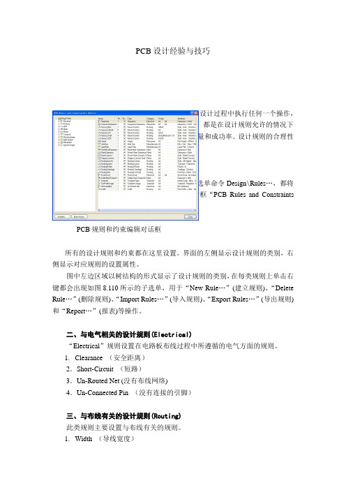
一、PCB设计规则和约束编辑对话框执行选单命令Design\Rules…,或单击右键选单命令Design\Rules…,都将弹出如图8.109所示的PCB规则和约束编辑对话框“PCB Rules and Constraints Editor”。
PCB规则和约束编辑对话框所有的设计规则和约束都在这里设置。
界面的左侧显示设计规则的类别,右侧显示对应规则的设置属性。
图中左边区域以树结构的形式显示了设计规则的类别,在每类规则上单击右键都会出现如图8.110所示的子选单,用于“New Rule…”(建立规则)、“Delete Rule…”(删除规则)、“Import Rules…”(导入规则)、“Export Rules…”(导出规则)和“Report…”(报表)等操作。
二、与电气相关的设计规则(Electrical)“Electrical”规则设置在电路板布线过程中所遵循的电气方面的规则。
1.Clearance (安全距离)2.Short-Circuit (短路)3.Un-Routed Net (没有布线网络)4.Un-Connected Pin (没有连接的引脚)三、与布线有关的设计规则(Routing)此类规则主要设置与布线有关的规则。
1.Width (导线宽度)2.Routing Topology (拓扑规则)3. Routing Priority (布线优先级)1.Routing Layers (布线板层)2.Routing Corners (布线拐角)四、与SMD布线有关的设计规则(SMT)五、与焊盘延伸量有关的设计规则(Mask)六、与内层有关的设计规则(Plane)七、与测试点有关的设计规则(Testpoint)八、与电路板制造有关的设计规则(Manufacturing)九、与高频电路设计有关的规则(High Speed)十、与元件的布局有关的规则(P1acement)1.Room Definition 用于定义元件合的尺寸及其所在的板层。

设计应用技术DOI:10.19399/j.cnki.tpt.2023.02.019STN网络建设策略分析王文华(广西通信规划设计咨询有限公司,广西南宁530007)摘要:随着5G技术的不断发展,我国5G技术已经从科研阶段正式朝着民用阶段拓展。
在商业化部署过程中,需要重点考虑的问题之一是空间变换网络(Spatial Transformer Network,STN)的建设方法。
5G网络本身具有大带宽、低时延、多连接等特点,支持不同运营商之间的共同建设。
在进行STN回传网络构架建设时,要充分结合5G网络的特点。
重点阐述了骨干层、汇聚层以及接入层的多阶段架构模式,对5G基站流量测算模型和低延时解决方案进行探讨,并对4类不同前传引入段光缆的场景进行了综合造价分析。
关键词:空间变换网络(STN);共建共享;流量测算;回传网络Analysis of STN Network Construction StrategyWANG Wenhua(Guangxi Communication Planning and Design Consulting Co., Ltd., Nanning 530007, China) Abstract: With the continuous development of 5G technology, China's 5G technology has officially expanded from the scientific research stage to the civilian stage. In the process of commercial deployment, one of the key issues to be considered is the construction method of Spatial Transformer Network (STN). The 5G network itself has the characteristics of large bandwidth, low delay and multi-connection, which supports the joint construction between different operators. When constructing STN backhaul network architecture, we should fully combine the characteristics of 5G network. The multi-stage architecture model of backbone layer, convergence layer layer and access layer is emphasized, the traffic measurement model and low-delay solution of 5G base station are discussed, and the comprehensive cost analysis of four different scenarios of fiber optic cables is made.Keywords: Spatial Transformer Network (STN); building and sharing; flow measurement; return network0 引 言在国家整体规划中,要求积极推进5G通信技术和超宽带技术的发展,5G技术逐渐向商用领域深入渗透。

PADSTACK:就是一组PAD的总称。
Copper pad:在布线层(routing layer),注意不是内层,任何孔都会带有一个尺寸大于钻孔的铜盘(copper pad).对内布线层这个铜盘大概14 mils,外布线层更大.如果这里需要导线连接,那么这个可以提供一个可供焊接的"盘". 对上下两个布线层(top and bottom routing layers)这个盘可以起到加固作用,防止"拨皮".如图中PIN->TOP,PIN->BOTTOM.Plating barrel:孔的周围被镀上锡膏后是不是象个圆桶.ANTIPAD:它就是一个在PLANE LAYER(内层)用于隔离孔与内层电器连接的围绕在孔周围的隔离环.如果孔在内层中不需要电器连接,就需要ANTIPAD来隔离. 在GERBER胶片中ANTIPAD表现为一个黑色或有色色环.其内径当然要大于孔的外径.现在考虑内层(plane layer),假设我们要一个40 mil的孔,我们就需要一个7mils 宽的铜环. 这样铜盘就是54mil宽(内径27mil).如果这个铜盘在该层不要导线连接,那么它就需要一个宽15 mils的"护城河"(宽度依赖于扳子的breakdown标准而定).而这个"护城河"就是"antipad".决大多数PCB设计软件都将内层表示成"负片"形式,这样有铜的地方就表现为"空"的,相反无铜的地方表现为有"色"的. 这样,这里的"antipad"会显示为一个有色环.(如果在routing layers,那么相反) 于是,我们可以得到这个antipad其宽为54 mils,外宽84 mils.在这个隔离环的内部的铜都连接在"锡桶"(plating barrel)上.如图中,从上到下的第三层(即第二内层)上有一个ANTIPAD,说明该孔和该层无电器连接。
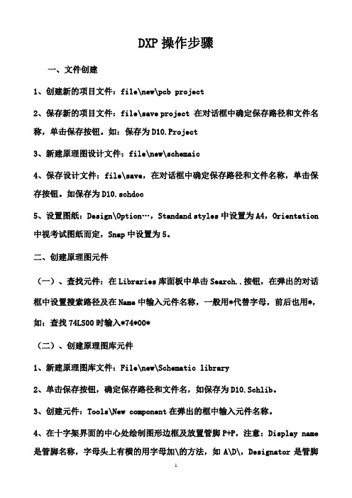
DXP操作步骤一、文件创建1、创建新的项目文件:file\new\pcb project2、保存新的项目文件:file\save project 在对话框中确定保存路径和文件名称,单击保存按钮。
如:保存为D10.Project3、新建原理图设计文件:file\new\schemaic4、保存设计文件:file\save,在对话框中确定保存路径和文件名称,单击保存按钮。
如保存为D10.schdoc5、设置图纸:Design\Option…,Standand styles中设置为A4,Orientation 中视考试图纸而定,Snap中设置为5。
二、创建原理图元件(一)、查找元件:在Libraries库面板中单击Search..按钮,在弹出的对话框中设置搜索路径及在Name中输入元件名称,一般用*代替字母,前后也用*,如:查找74LS00时输入*74*00*(二)、创建原理图库元件1、新建原理图库文件:File\new\Schematic library2、单击保存按钮,确定保存路径和文件名,如保存为D10.Schlib。
3、创建元件:Tools\New component在弹出的框中输入元件名称。
4、在十字架界面的中心处绘制图形边框及放置管脚P+P,注意:Display name 是管脚名称,字母头上有横的用字母加\的方法,如A\D\,Designator是管脚序号,Electrical type是电气特性,电源及地设为power,其余设置为Passive。
注意有些集成块的电源与地是隐藏的,先放好再隐藏。
放置时将管脚和栅格线对齐。
最重要的是放管脚,对边框不要很严格。
做完后记得保存。
(三)、库中有类似的元件可在查找后放到原理图中,双击该元件取消[Lock Pins]复选框的选中状态,这样可直接修改管脚。
改完后记得打勾打上。
(四)、制作含有子件的元件:利用第二种方法绘制第一个子件。
执行Tools\New Part 绘制其它子件。

3COM SWITCH 5500 FAMILY IN AN ENTERPRISE CAMPUS NETWORK5Suggested Service, Support and Training OfferingsNetwork Health CheckAn activity-auditing service focused on improving network performance and productivityIncludes traffic monitoring, utilization analysis, problem identification, and asset deployment recommendations Extensive report provides blueprint for actionNetwork Installation and Experts set-up and configure equipment and integrate technologies to Implementation Servicesmaximize functionality and minimize business disruptionFor large and complex sites, implementation services include personalized configuration, project management, extended testing and coaching on network administrationProject ManagementProvides extra focus and resources that special projects demand 3Com engineers manage entire process from initial specifications to post-project reviewUsing structured methodology, requirements are identified, projects planned and progress of implementation activities tracked3Com Guardian SM Maintenance Service This service provides comprehensive on-site support and includesadvance hardware replacement, telephone technical support and software upgrades 3Com Express SM Maintenance Service This service provides speedy access to: 3Com shipment of advance hardware replacements, software upgrades and telephone support 3Com UniversitySelf-paced and instructor-led technology and product courses, plus certification programs3Com Global Services offers the resources and talents of a major corporation plus more than two decades of experience in resolving network challenges and delivering business benefits to enterprises around the world.Global support with a personalized focus in the local language helps drive productivity and minimize expenses. Because 3Com understands both the technology and the business, we’re the partner you need, to maintain your competitive edge and remain strong.SERVICE AND SUPPORTWarranty3Com Limited Lifetime Warranty. For as long as the original end user owns the product, or for five years after 3Com discontinues the sale of the product, whichever occurs first.Hardware coverageCovers the complete unit including power supply and fan.In-warranty hardware replacement *Advanced Hardware Replacement of hardware for the duration of the warranty. In the US 48 contiguous states this is same-day ship with next business day delivery when call received before noon Pacific time. For Canada, Alaska and Hawaii, this is same-day ship when call received before noon Pacific time. In Western Europe, this is same-day ship when call received before noon Greenwich time. For the rest of the world, it is next-business-day ship. Actual delivery times may vary depending on customer location. Reasonable commercial efforts apply.Software coverage 90 days for media replacement.Software updates*Access to maintenance and bug fix releases for the software version purchased for the duration of the warranty.Online Knowledgebase support*Access to online troubleshooting tool for the duration of the warranty.*These services are not included as part of the Warranty and 3Com reserves the right to modify or cancel this offering at any time, without advance notice. This offering is not available where prohibited by law. Services are effective at warranty start date, and are enabled with product registration. Customers receive a user ID with eSupport registration.PRODUCT WARRANTY AND OTHER SERVICESAll information in this section is relevant to all members of the 3Com Switch 5500 10/100 family, unless otherwise stated.CONNECTORS52-port models48 auto-negotiating 10BASE-T/100BASE-TX ports configured as auto-MDI/MDIX; IEEE 802.3af in-line power for PWR models4Gigabit SFP ports28-port non-FX models24 auto-negotiating 10BASE-T/100BASE-TX ports configured as auto-MDI/MDIX; IEEE 802.3af in-line power for PWR models4Gigabit SFP ports28-port FX24 SFP ports, to be populated with 100BASE-X SFP multi- or single-mode transceivers2auto-negotiating 10BASE-T/100BASE-TX/1000BASE-T ports configured as auto-MDI/MDIX2Gigabit SFP portsPERFORMANCE52-port17.6 Gbps switching capacity,max. 13.1 Mpps forwarding rate, max.28-port12.8 Gbps switching capacity, max. 9.5 Mpps forwarding rate, max.All modelsWirespeed performance across all ports within stack or fabricStore-and-forward switching; latency<10 µs2Gbps full-duplex stacking bandwidthLAYER 2 SWITCHING16K MAC addresses in address table Static MAC addresses: 256 (EI models);64 (SI models); in addition to default addressJumbo Frame support (EI models only) Port-based IEEE 802.1Q VLANs:4,094 (EI models); 256 (SI models) IEEE 802.1 Q-in-Q double-tagged VLANs(EI models only)IEEE 802.1v protocol-based VLANs (EI models only)MAC-based VLANs using RADA auto-VLAN assignmentAuto-voice VLANIEEE 802.3ad Link Aggregation Control Protocol (LACP); automated and manual aggregationLink aggregation trunk groups,per switch:•26 (52-port); 14 (28-port)•810/100 ports or 8 SFP ports per group•8 Distributed Link Aggregation (DLA) groupsAuto-negotiation and manual configuration of port speed and duplex IEEE 802.3x full-duplex flow control Back pressure flow control for half-duplexUnidirectional Link Detection (UDLD)Broadcast, Multicast and Unicasttraffic suppressionIEEE 802.1D Spanning Tree Protocol(STP)IEEE 802.1w Rapid Spanning TreeProtocol (RSTP)IEEE 802.1s Multiple Spanning TreeProtocol (MSTP)Bridge Protocol Data Unit (BPDU)protectionSpanning Tree root guardInternet Group Management Protocol(IGMP) v1 and v2 snoopingIGMP querierFiltering for 256 multicast groupsLAYER 3 SWITCHINGHardware based routingStatic routes: 256 (EI models);64 (SI models);in addition todefault addressAddress Resolution Protocol (ARP)entries: 4K dynamic, 1K static(EI models); 2K dynamic, 256 static(SI models)IP interfaces: 32 (EI models);4(SI models)Routing Information Protocol (RIP),v1 and v2: 2K routes (EI models);1K(SI models)Open Shortest Path First (OSPF)(EI models only):•2 areas with 4 virtual interfacesper area•2neighbors per virtual interface•2virtual linksProtocol Independent Multicast-DenseMode (PIM-DM) (EI models only)Protocol Independent Multicast-SparseMode (PIM-SM) (EI models only)IGMP v1 and v2Equal Cost Multipath Protocol (ECMP)Multicast VLAN Registration (MVR)Dynamic Host Configuration ProtocolRelay(DHCP Relay): 4 K max.(EI models); 2K max.(SI models)3Com XRN®Technology:•Resilient stacking and fabric linksup to 70 km (43.5 mi)•Distributed Link Aggregation, hot-swappable switch units; high-speedfully resilient trunks up to 8 Gbps•Distributed Resilient Routing:optimized Layer 3, one routing tableper switch (EI models only)Virtual Router Redundancy Protocol(VRRP): EI models OnlyCONVERGENCE8hardware queues per portIEEE 802.1p Class of Service/Qualityof Service (CoS/QoS) on ingress andegressRemarking of packets based onpriority:•Type of Service (ToS)•IEEE 802.1p CoS•IP precedence•Physical port•Source/destination MAC address•VLAN information•Ethertype•Source/destination IP address•Source/destination TCP port•Source/destination UDP portWebcache redirection (EI models only)Time-based Access Control Lists(ACLs) (EI models only)Auto-prioritization of voice trafficdetermined by vendor OUIWeighted Round Robin (WRR),including WRR+SPWeighted Fair Queuing (WFQ),including WFQ + SPStrict Priority Queuing (SPQ)Weighted Random Early Discard(WRED)DiffServ Code Point ExpeditedForwarding (DSCP EF) remarking forprioritization of VoIP trafficApplication rate limiting and blockingon ingressPort-based traffic shaping on egressIEEE 802.3af Power over Ethernetstandards-compliant (PWR models)POE (PWR MODELS ONLY)IEEE 802.3af PoE injection into Cat5or 5e LAN wiring (300 W total max.)Supports all standard and mostcommon pre-standard phones, accesspoints and other PoE devices fromselected vendors(Cisco,Nortel,Philips, Siemens, Avaya, NEC,Polycom, Pingtel, Proxim, et. al.)A vailable standards-based supplementalpower system enables full 15.4 W toall PoE ports in a switch or stackSECURITYIEEE 802.1X Network login userauthentication:•Local, RADIUS,or TACACS+ serverauthentication•P AP, CHAP, EAP over LAN (EAPoL),EAP-TLS/TTLS and PEAP•Automatic port assignment ofVLANs,ACLs and QoS profile basedon user•Multiple users per port•1,024 users per fabric•Guest VLAN option•Multiple authentication server realmdefinitionsRADIUS/TACACS+ session accountingRADIUS Authenticated Device Access(RADA): authenticate devices basedon MAC address against RADIUSserver or local database; assign VLANID and ACL through RADIUSCombined MAC and IEEE 802.1Xauthentication on same portDHCP Tracker (EI models only)DHCP snooping, including DHCP TrustWirespeed packet filtering in hardwareACLs filter at Layers 2, 3 and 4:•Source/destination MAC address•Ethernet type•Source/destination IP address•Source/destination TCP port•Source/destination UDP portUser-defined ACL filters(EI models only)Port-based MAC address DisconnectUnknown Device (DUD)IEEE 802.1X or TACACS+ userauthentication of switch managementon Telnet and console sessionsMD5 cipher-text and clear-textauthentication for OSPF v2 and RIPv2 packets and SNMP v3 trafficHierarchical management and passwordprotection for management interfaceand encrypted traffic, with SNMP v3and SSH v24local user access privilege levelsTrusted management station IP and/orMAC addressSTACKINGUp to 400 user ports, including up to384 10/100 portsSingle IP address and managementinterfaces for stack-wide controlHot-swappable, resilient stackingDistributed stacking over standardmedia with links up to 70 km (43.5 mi)XRN Stacking Technology of up toeight units highDistributed Resilient Routing withrouter tables in all units; no master/slave arrangement (EI models only)Stack Switch 5500 EI models onlywith other like units using XRNTechnology via SFP portsStack Switch 5500 SI models only withother like units using SFP portsMANAGEMENTCLI via console or TelnetEmbedded web management interfaceSystem configuration with SNMP v1,2c and 3Comprehensive statistics,includingACL/QoS and IP interfaceSyslogRemote Monitoring (RMON) groupsstatistics,history,alarm and eventsDHCP server including options 60, 82and 184 (EI models only)Supports multiple software images andbank swap, stored in non-volatilememoryConfiguration conversion tool formigration from Switch 3300, 4200and 4400 to Switch 55001-to-1 port mirroringAbility to apply ACL to mirror portand forward only certain traffic typesMany-to-1 port mirroring(EI models only)VLAN-to-1 port mirroring(EI models only)Remote port mirroring (EI models only)Detailed alarm and debug informationFront panel indicators for port andunit status informationSupports ping,remote ping andtracerouteConfiguration file for backup andrestore, stored in non-volatilememory; multiple configuration filesavailableBackup and restore of software imagesNetwork Time Protocol (NTP)DHCP Relay and UDP HelperSystem file transfer mechanisms:Xmodem, FTP, Trivial FTP (TFTP),Secure FTP (SFTP)6 SPECIFICATIONS3Com management applications:•3Com Enterprise Management Suite for flexible, extensible management in advanced enterprise IT environ-ments•3Com Network Director for comprehensive, turn-key network management for the enterprise•3Com Network Supervisor for basic, turn-key network management for mid-market businesses•3Com Network Access Manager for IEEE 802.1X and RADA integration with IAS/Active Directory•3Com Switch Manager for virtual clustering support across 3Com switch familiesDIMENSIONSHeight: 43.6 mm (1.7 in or 1 RU) Width: 440.0 mm (17.3 in)Depth: 270.0 mm (10.6 in)(PWR models: 427.0 mm (16.8 in)) Weight: 3.3 kg (7.3 lb)(PWR models: 6.3 kg (13.9 lb))POWER SUPPLYMode support: AC-only, AC and DC, DC-only operationBuilt-in DC power stage for direct connection to -48 V supplyAC line frequency: 50/60 HzInput voltage: 90-240 V ACAC current rating: 1.0A max. (PWR models: 7.0A max.)DC current rating: 2.0A max. (PWR 28-port: 12.0A;PWR 52-port: 19.5A; max.)ENVIRONMENTALOperating temperature: 0°to 40°C(32°to 104°F)Operating altitude: 0 to 4,572 meters(0 to 15,000 feet)Storage temperature: -40°to 70°C(-40°to 158°F)Humidity (operating and storage):10% to 95% non-condensingStandard: EN 60068 (IEC 68)Sound pressure level (dBA):•52-port: 46.5 decibels•52-port PWR: 46.3 decibels•28-port: 40.1 decibels•28-port PWR: 47.3 decibels•28-port FX: 51.3 decibelsRELIABILITY(MTBF @ 25°C)52-port: 44 years (385,000 hours)52-port PWR: 21 years (184,000 hours)28-port: 53 years (464,000 hours)28-port PWR: 30 years (263,000 hours)28-port FX: 38 years (332,000 hours)INDUSTRY STANDARDSSUPPORTEDEthernet ProtocolsIEEE 802.1D (STP)IEEE 802.1p (CoS)IEEE 802.1Q (VLANs)IEEE 802.1s (MSTP)IEEE 802.1v (Protocol VLANs)IEEE 802.1w (RSTP)IEEE 802.1X (Security)IEEE 802.3 (Ethernet)IEEE 802.3ab(1000BASE-T)IEEE 802.3ad (Link Aggregation)IEEE 802.3af (Power over Ethernet)IEEE 802.3i (10BASE-T)IEEE 802.3u (100BASE-TX/-FX)IEEE 802.3x (Flow Control)IEEE 802.3z (1000BASE-X)Management, including MIBsSupportedRFC 768 (UDP)RFC 783 (TFTP)RFC 791 (IP)RFC 792 (ICMP)RFC 793 (TCP)RFC 826 (ARP)RFC 1058 (Routing InformationProtocol)RFC 1112 (IP Multicasting)RFC 1157 (SNMP)RFC 1213/2233 (MIB II)RFC 1253 (OSPF Version 2 MIB)RFC 1583 (OSPF Version 2)RFC 1587 (OSPF NSSA Option)RFC 1724 (RIP Version 2 MIBExtension)RFC 1757 (RMON)RFC 1812 (Requirements for IPv4Routers)RFC 1850 (OSPF Version 2 MIB)RFC 1907 (SNMP Version 2c MIB)RFC 2021 (RMON II Probe ConfigMIB)RFC 2154 (OSPF Digital Signatures)RFC 2233 (Interfaces MIB)RFC 2236 (IGMP V2)RFC 2328 (OSPF Version 2)RFC 2338 (VRRP)RFC 2362 (PIM-SM)RFC 2571 (FrameWork)RFC 2571-2575 (SNMP)RFC 2613 (Remote NetworkMonitoring MIB Extensions)RFC 2618 (RADIUS AuthenticationClient MIB)RFC 2620 (RADIUS Accounting ClientMIB)RFC 2644 (Restricted DirectedBroadcast)RFC 2665 (Pause Control)RFC 2668 (IEEE 802.3 MAU MIB)RFC 2674 (VLAN MIB Extension)RFC 2819 (RMON groups Alarm,Event, History and Statistics only)RFC 2819 (RMON MIB)RFC 3414 (SNMP Version 3 USM)RFC 3415 (SNMP Version 3 V ACM)SNMP v3 and RMON RFC supportEMISSIONS / AGENCY APPROVALSCISPR 22 Class AFCC Part 15 Class AEN 55022 1998 Class AEN 61000-3-2 2000, 61000-3-3ICES-003 Class AVCCI Class AIMMUNITYEN55024SAFETY AGENCY CERTIFICATIONSUL 60950IEC 60950-1EN 60950-1CAN/CSA-C22.2 No. 60950-1-03WARRANTY AND OTHER SERVICESLimited Lifetime Hardware Warranty,including fans and power supplyLimited Software Warranty for 90 daysAdvance Hardware Replacementwith Next Business Day shipment inmost regions90 days of telephone technical supportRefer to /warrantyfor details.SPECIFICATIONS (CONTINUED)REDUNDANT POWER SYSTEM 3Com has tested and qualified a Redundant Power System (RPS) solution designed for the Switch 5500 family by Eaton Powerware Corporation, a leading global provider of power quality and management solutions. The Powerware DC RPS systems come in either 3RU or 6RU form-factors, delivering up to 9,000W of DC power to a stack of Switch 5500 units. The 3RU RPS unit houses up to three hot-swappable rectifiers supplying up to 4,500W of power that supports up to eight separately-fused DC outputs, while the 6RU unit can house up to six hot-swappable rectifiers provisioning a total of 9,000W.The RPS supports SNMP management, including MIB II, which is easily accessible through the built-in RJ-45 or serial port. It is fully compatible with the IEEE 802.3af Power over Ethernet standard, providing supplemental power for the 3Com Switch 5500 PWR models.With this RPS, all 384 10/100 ports on a stack of eight Switch 5500 PWR 52-port units can receive the industry standard15.4W of power per port, with N+1 power redundancy.The RPS ships with the power input fully configured and can be connected to a UPS with battery backup. For more details, please refer to /rps.7。
PCB各层介绍及AD软件画PCB时的规则好久没画过板了,最近因为⼯作关系,硬件软件全部得⾃⼰来,不得不重新打开闲置很久的AltiumDesigner。
以前做过点乱七⼋糟的笔记,本来想回头翻看⼀下,结果哪⼉也找不到,估计已经被不⼩⼼删掉了。
曾经挺熟悉的东西,现在⼀打开竟然处处遇坎⼉,很多操作都忘记了,看来不留好笔记是不⾏的,不然很多东西过段时间不⽤,再⽤的时候就跟新学⼀样了,还得到处找资料。
吸取教训,以后有点什么⼩note都要有条理的记录收藏起来。
PCB各层说明:丝印层(OverLay,Silkscreen):有顶层丝印和底层丝印。
⽤来画器件轮廓,器件编号和⼀些图案等。
信号层(SignalLayer):对于两层板,主要是TopLayer和BottomLayer层。
多层板的话还有若⼲个中间层(Mid)内部电源/接地层(Internal Planes):内部电源/接地层主要⽤于4层以上印制电路板作为电源和接地专⽤布线层。
阻焊层(Solder Mask):绿油覆盖层。
这⼀层是负⽚输出。
阻焊区域⼀般⽐焊盘区域稍⼤。
AD9中可通过规则设置阻焊层的⼤⼩,如下图。
锡膏防护层(Paste Mask):这⼀层主要⽤来制作钢⽹,这⼀层不⽤发给PCB⼚家,⽽应发给回流焊⼚家。
也是负⽚输出。
锡膏层⼀般⽐焊盘区域稍⼩。
AD9中可通过规则设置锡膏层的⼤⼩,如下图(下图中的规则是锡膏层与焊盘区⼀样⼤。
锡膏层只能⽐焊盘区⼩或⼀样⼤,否则锡膏层略⼤可能引起相邻的焊盘短路)。
禁⽌布线层(Keep Out):圈定布线区域。
(只针对⾃动布线?如果有机械层的话,⼿动布线时可以⽆视这层?)多层⾯,PCB板的所有层(Multi Layer):涵盖了PCB的所有层。
机械层(Mechanical Layers):机械层⼀般⽤来绘制印制电路板的边框(边界),通常只需使⽤⼀个机械层。
(疑:跟禁⽌布线层什么关系?禁⽌布线层包含在机械层之内?如果没有机械层,PCB⼚商会将禁⽌布线层当做机械层来做?)钻孔层(Drill):分为钻孔引导层(DrillGuide)和钻孔数据层(DrillDrawing),⽤于绘制钻孔孔径和孔的定位。
焊盘知识一个典型的四层板padstack如图所示:PADSTACK:就是一组PAD的总称。
Copper pad:在布线层(routing layer),注意不是内层,任何孔都会带有一个尺寸大于钻孔的铜盘(copper pad).对内布线层这个铜盘大概14 mils,外布线层更大.如果这里需要导线连接,那么这个可以提供一个可供焊接的"盘".对上下两个布线层(top and bottom routing layers)这个盘可以起到加固作用,防止"拨皮".如图中PIN->TOP,PIN->BOTTOM。
Plating barrel:孔的周围被镀上锡膏后是不是象个圆桶。
ANTIPAD:它就是一个在PLANE LAYER(内层)用于隔离孔与内层电器连接的围绕在孔周围的隔离环.如果孔在内层中不需要电器连接,就需要ANTIPAD来隔离.在GERBER胶片中ANTIPAD表现为一个黑色或有色色环.其内径当然要大于孔的外径。
现在考虑内层(plane layer),假设我们要一个40 mil的孔,我们就需要一个7mils宽的铜环.这样铜盘就是54mil宽(内径27mil).如果这个铜盘在该层不要导线连接,那么它就需要一个宽15 mils的"护城河"(宽度依赖于扳子的breakdown标准而定).而这个"护城河"就是"antipad".决大多数PCB设计软件都将内层表示成"负片"形式,这样有铜的地方就表现为"空"的,相反无铜的地方表现为有"色"的.这样,这里的"antipad"会显示为一个有色环.(如果在routing layers,那么相反)于是,我们可以得到这个antipad其内径宽为54 mils,外宽84 mils.在这个隔离环的内部的铜都连接在"锡桶"(plating barrel)上.如图中,从上到下的第三层(即第二内层)上有一个ANTIPAD,说明该孔和该层无电器连接。