西门子LOGO!控制系统的设计与编程
- 格式:pptx
- 大小:4.24 MB
- 文档页数:111
基于西门子LOGO!的真空泵自动控制系统设计本设计基于西门子 LOGO!的真空泵自动控制系统,主要实现对真空泵的自动控制,提高了生产效率,减少了人工操作。
下面将从需求分析、硬件选型、软件设计和测试验证四个方面进行详细介绍。
需求分析本系统需要实现以下功能:1. 自动打开和关闭真空泵;2. 实时监测真空泵的工作状态(如泵速、泵压);3. 报警提示功能,当真空泵异常时能够发出警报,并记录异常信息;4. 根据生产计划进行自动化管理,能够自动调整真空泵工作时间,实现生产计划的自动化控制。
硬件选型本系统选用西门子 LOGO!作为控制器,真空泵直接连接在其输出端子上,可以实现对真空泵的控制。
同时,系统还需要具备一个实时监测真空泵状态的传感器,采用了压力传感器进行监测,并与 LOGO!控制器进行通讯。
此外,系统还需要一块人机界面屏幕,用于操作和监测系统状态。
软件设计本系统的软件设计分为两部分:PLC编程和人机界面编程。
1. PLC编程:主要实现控制器与真空泵、传感器之间的通讯和控制逻辑,包括打开/关闭真空泵、读取压力传感器的数据以及根据生产计划调整真空泵工作时间。
2. 人机界面编程:主要实现操作界面的设计和生产计划的管理。
操作界面需要实现打开/关闭真空泵、查看真空泵状态和记录异常信息的功能,生产计划管理需要实现设置生产计划和监测生产进度。
测试验证系统测试主要分为功能测试和性能测试两部分。
1. 功能测试:测试系统各项功能是否可行,包括自动打开和关闭真空泵、实时监测真空泵状态、警报提示和自动化生产计划管理。
2. 性能测试:测试系统响应速度、控制精度和可靠性等方面。
结论。
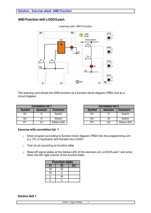
AND-Function with LOGO!LearnLearning card: AND-FunctionThe learning card shows the AND-function as a function block diagram (FBD) and as acircuit diagram.Correlation list 1Correlation list 2Symbol absolute Comment Symbol absolute Comment S1 I1 Switch S3 I7 Switch S2 I3 Switch S4 I8 SwitchLED P2 Q3LEDStatusStatusP1 Q1Exercise with correlation list 1o Enter program according to function block diagram (FBD) into the programming unit(i.e. PC or keyboard) and transfer into LOGO!o Test circuit according to function tableo Read-off signal states at the Status-LED of the exercise unit …LOGO!Learn“ and enter them into the right column of the function table.Function tableI1 I3 Q1H HH LL HL LSolution field 1Exercise with correlation list 2o Enter program according to ladder diagram (LAD) into the programming unit (i.e. PC or keyboard) and transfer into LOGO!o Test circuit according to function table.o Read-off signal states at the Status-LED of the exercise unit …LOGO!Learn“ and enter them into the right column of the function table.o Draw the ladder diagram together with the respective parameters into the solution field.Function tableI7 I8 Q3H H HH L LL H LL L LSolution field 2OR-Function with LOGO!LearnLearning card: OR-FunctionThe learning card shows the OR – Function as function block diagram (FBD) and as circuit diagram.Correlation list 1Correlation list 2Symbol absolute Comment Symbol absolute Comment S1 I1 Switch S3 I7 Switch S2 I3 Switch S4 I8 SwitchLEDStatus P1 Q1LED P2 Q3StatusExercise with Correlation list 1o Enter program according to function block diagram (FBD) into the programming unit(i.e. PC or keyboard) and transfer into LOGO!o Test circuit according to function table.o Read-off signal states at the Status-LED of the exercise unit …LOGO!Learn“ and enter them into the right column of the function table.Function tableI1 I3 Q1H H HH L HL H HL L LSolution field 1Exercise with correlation list 2o Enter program according to ladder diagram (LAD) into the programming unit (i.e. PC or keyboard) and transfer into LOGO!o Test circuit according to function table.o Read-off signal states at the Status-LED of the exercise unit …LOGO!Learn“ and enter them into the right column of the function table.Function tableI7 I8 Q3H H HH L HL H HL L LSolution field 2NOT - Function (Reverse step) with LOGO!LearnLearning card: NOT-FunctionThe learning card shows the NOT- Function as a function block diagram (FBD) and as acircuit diagram.Correlation list 1Correlation list 2Symbol absolute Comment Symbol absolute Comment S1 I1 Switch S2 I7 SwitchStatusLEDLED P2 Q4 P1 Q1StatusExercise with Correlation list 1o Enter program according to function block diagram (FBD) into the programming unit(i.e. PC or keyboard) and transfer into LOGO!o Test circuit according to function table.o Read-off signal states at the Status-LED of the Exercise unit …LOGO!Learn“ and enter them into the right column of the function table.I1 Q1H LL HSolution field 1Exercise with correlation list 2o Enter program according to ladder diagram (LAD) into the programming unit (i.e, PC or keyboard) and transfer into LOGO!o Test circuit according to function table.o Read-off signal states at the Status-LED of the exercise unit …LOGO!Learn“ and enter them into the right column of the function table.I7 Q4H LL HSolution field 2NAND - Function with LOGO!LearnLearning card: NAND – FunctionThe learning card shows the NAND -Function as a function block diagram (FBD) and as acircuit diagram.If an AND-Function and a NOT-Function are interconnected, all output states at output (Q)are reversed (negated). At output …Q“ of a NAND -Function state …H“ exists if state …H“ is notpresent on any of the inputs.Correlation list 1Correlation list 2Symbol absolute Comment Symbol absolute Comment S1 I1 Switch S3 I7 Switch S2 I3 Switch S4 I8 SwitchLEDStatus P1 Q1StatusLED P2 Q4Exercise with correlation list 1o Enter program according to function block diagram (FBD) into the programming unit(i.e. PC or keyboard) and transfer into LOGO!o Test circuit according to function table.o Read-off signal states at the Status-LED of the exercise unit …LOGO!Learn“ and enter them into the right column of the function table.Function tableI1 I3 Q1H H LH L HL H HL L HSolution field 1Exercise with correlation list 2o Enter program according to ladder diagram (LAD) into the programming unit (i.e.PC or keyboard) and transfer into LOGO!o Test circuit according to function table.o Read-off signal states at the Status-LED of the exercise unit …LOGO!Learn“ and enter them into the right column of the function table.Function tableI7 I8 Q4H H LH L HL H HL L H Solution field 2NOR - Function with LOGO!LearnLearning card: NOR - FunctionThe learning card shows the NOR - Function as a function block diagram (FBD) and as a circuit diagram.If an OR-Function and a NOT-Function are interconnected, all output states at output (Q) are reversed (negated). At output …Q“ of a NOR – Function state …H“ exists if state …H“ is not present on any of the inputs.Correlation list 1Correlation list 2Symbol absolute Comment Symbol absolute Comment S1 I1 Switch S3 I5 Switch S2 I3 Switch S4 I6 Switch P1 Q1 Status LEDP2 Q4StatusLEDExercise with correlation list 1o Enter program according to function block diagram (FBD) into the programming unit(i.e. PC or keyboard) and transfer into LOGO!o Test circuit according to function table.o Read-off signal states at the Status-LED of the exercise unit …LOGO!Learn“ andenter them into the right column of the function table.Function table I1 I3 Q1 H H L H L L L H L L L HSolution field 1Exercise with correlation list 2o Enter program according to ladder diagram (LAD) into the programming unit (i.e.PC or keyboard) and transfer into LOGO!o Test circuit according to function table.o Read-off signal states at the Status-LED of the exercise unit …LOGO!Learn“ and enter them into the right column of the function table.Function tableI7 I8 Q4H H LH L LL H LL L HSolution field 2XOR – Function (Exclusive-OR) with LOGO!LearnLearning card: XOR - FunctionThe learning card shows the XOR -Function as a function block diagram (FBD) and as acircuit diagram.Often a combination of logic gates is required which always has …H“ at the output if the initialstates (input values) are different. Such a function is also called an Exclusive-OR.Correlation list 1Correlation list 2Symbol absolute Comment Symbol absolute Comment S1 I1 Switch S3 I5 Switch S2 I3 Switch S4 I6 SwitchLEDStatus P1 Q1StatusLED P2 Q4Exercise with correlation list 1o Enter program according to function block diagram (FBD) into the programming unit(i.e. PC or keyboard) and transfer into LOGO!o Test circuit according to function table.o Read-off signal states at the Status-LED of the exercise unit …LOGO!Learn“ and enter them into the right column of the function table.o Draw the ladder diagram together with the respective parameters into the solution field.Funcion tableI1 I3 Q1H H LH L HL H HL L LSolution field 1Exercise with correlation list 2o Enter program according to ladder diagram (LAD) into the programming unit (i.e. PC or ketboard) and transfer into LOGO!o Test circuit according to function table.o Read-off signal states at the Status-LED of the exercise unit …LOGO!Learn“ and enter them into the right column of the function table.o Draw the ladder diagram together with the respective parameters into the solution field.Function tableI5 I6 Q4H H LH L HL H HL L LSolution field 2Combined circuit: AND before OR with LOGO!LearnLearning card: AND before ORThe learning card shows the combined circuit: AND before OR is depicted as circuit diagram.Output P1 carries an H-signal only if the AND-condition is true on input S1 respectively S2 or if the input S3 respectively S4 carries an H-signal.Correlation listSymbol absolute CommentS1 I1 SwitchS2 I2 SwitchS3 I4 SwitchS4 I6 SwitchLEDP1 Q1 StatusExerciseo Convert circuit diagram into function block diagram (FBD) (Solution field 1).o Convert circuit diagram into ladder diagram (LAD) (Solution field 2).o Enter program according to function block diagram (FBD) into the programming unit(i.e. PC or keyboard) and transfer into LOGO!o Enter program according to ladder diagram (LAD) into the programming unit (i.e. PC or keyboard) and transfer into LOGO!o Test program..Solution field 1Solution field 2Alternating circuit with LOGO!LearnLearning card: Alternating circuitAn alternating circuit is used to switch a lamp E 1 (Q3) on or off with S1 or S8 from two different locations.Correlation listSymbol absolute CommentS1 I1 SwitchS8 I8 SwitchE1 Q3 Status LED (Pilot lamp)ExerciseSolution diagram 1 shows a suggested solution.o Enter program according to function block diagram (solution field 1) into the programming unit (i.e. PC or keyboard) and transfer into LOGO!o Test program.o Enter the solution …FBD“ as …LAD“ (ladder diagram) into solution field 2.o Enter program according to LAD (solution field 2) into the programming unit. (i.e. PC or keyboard) and transfer into LOGO!o Test program.Solution field 1 (suggested solution)Solution field 2 (ladder diagram)3-way circuit with LOGO!LearnLearning card: 3-way circuitA 3-way circuit is used to switch lamp E1 (Q2) on or off from three different locations with S1, S2 or S3.Correlation listSymbol absolute CommentS1 I1 SwitchS2 I2 SwitchS3 I3 SwitchE1 Q1 Status LED (Pilot lamp)ExerciseSolution diagram 1 shows a suggested solution.o Enter program according to function block diagram (solution field 1) into the programming unit (i.e. PC or keyboard) and transfer into LOGO!o Test programo Enter the solution …FBD“ as …LAD“ (ladder diagram) into solution field 2.o Enter program according to LAD (solution field 2) into the programming unit (i.e. PC or keyboard) and transfer into LOGO!o Test programSolutoin field 1 (suggested solution)Solution: 3-way circuit Solution field 2 (ladder diagram)Pulse Relay with LOGO!LearnLearning card: Pulse RelayA pulse relay circuit is used to switch lamps E1+E2 on or off from two different locations with S1 or S2.Correlation listSymbol absolute CommentS1 I1 ButtonS2 I5 ButtonE1 Q1 LampE2 Q2 LampExercise with correlation list 1o Enter program according to function block diagram (FBD) into the programming unit(i.e. PC or keyboard) and transfer into LOGO!o Draw function block diagram together with the respective parameters into solution field 1.o Draw ladder diagram into solution field 2.o Test programSolution field 1Solution field 2Stairway lighting switch with LOGO!LearnLearning card: Stairway lighting switchA stairway lighting switch is used to switch lamps E1+E2 on from two different locations with S1 or S2. The lamps then switch off automatically with a time delay.Correlation listSymbol absolute CommentS1 I6 ButtonS2 I7 ButtonE1 Q1 LampE2 Q2 LampExercise with correlation list 1o Enter program according to function block diagram (FBD) into the programming unit(i.e. PC or keyboard) and transfer into LOGO!o Draw function block diagram together with the respective parameters into solution field 1.o Draw ladder diagram into solution field 2.o Test programSolution field 1Solution field 2Switch-on delay with LOGO!LearnLearning card: Switch-on delayA circuit with a switch-on delay has to be tested. The example on the learning card is programmed for a delay time of 5 sec.Please programCorrelation listSymbol absolute CommentS1 I1 SwitchP1 Q4 Status LED (Pilot lamp)ExerciseSolution diagram 1 shows a suggested solution.o Enter program according to function block diagram (solution field 1) into the programming unit (i.e. PC or keyboard and transfer into LOGO!o Test programo Transfer the solution …FBD“ as …LAD“ (ladder diagram) into solution field 2.o Enter program according to LAD (solution field 2) into the programming unit (i.e. PC or keyboard) and transfer into LOGO!o Test program.Solution field 1 (suggested solution)Solution field 2 (ladder diagram)Switch-off delay with LOGO!LearnLearning card: Switch-off delayA circuit with a switch-off delay function has to be tested.The example on the learning card is programmed for a delay time of 5 sec.Please programCorrelation listSymbol absolute CommentS1 I1 SwitchP1 Q4 Status LED (Pilot lamp)ExerciseSolution diagram 1 shows a suggested solution.o Enter program according to function block diagram (solution field 1) into the programming unit (i.e. PC or keyboard) and transfer into LOGO!o Test programo Transfer the solution …FBD“ as “LAD“ (ladder diagram) into solution field 2.o Enter program according to LAD (solution field 2) into the programming unit (i.e. PC or keyboard) and transfer into LOGO!o Test program.Solution field 1 (suggested solution)Solution field 2 (ladder diagram)Exercise sheet: 1 of 3Selection circuit 1 of 3 with LOGO!LearnLearning card: Selection circuit 1 of 3The learning card shows the selection circuit 1 of 3 as a circuit diagram.Output P1 carries an H-Signal if only one switch is switched-on. If more then one switch is switched-on, output P1 (Q1) will carry an L-Signal.Correlation listSymbol absolute CommentS1 I1 SwitchS2 I2 SwitchS3 I3 SwitchLEDP1 Q1 StatusExerciseo Convert circuit diagram into function block diagram (FBD) (solution field 1).o Convert circuit diagram into ladder diagram (LAD) (solution field 2).o Enter program according to function block diagram (FBD) into the programming unit(i.e. PC or keyboard) and transfer into LOGO!o Enter program according to ladder diagram (LAD) into the programming unit (i.e. PC or keyboard) and transfer into LOGO!o Test program.Exercise sheet: 1 of 3 Solution field 1Solution field 2Selection circuit 2 of 3 with LOGO!LearnLearning card: Selection circuit 2 of 3The learning card shows the selection circuit 2 of 3 as a circuit diagram.Critical parameters in dangerous processes are monitored by several sensors.If a critical parameter (i.e. temperature of a chemical process) is only monitored by one measuring instrument, an error could occur due to a fault of a measuring device which could trigger a false alarm. Therefore, critical parameters are monitored threefold. The alarm will only be triggered, if at least two of the three measuring instruments indicate that they have exceeded the limit.Correlation listSymbol absolute CommentS1 I1 SwitchS2 I2 SwitchS3 I3 SwitchLEDP1 Q1 StatusExerciseo Convert circuit diagram into function block diagram (FBD) (solution field 1)o Convert circuit diagram into ladder diagram (LAD) (solution field 2)o Enter program according to function block diagram (FBD) into the programming unit(i.e. PC or keyboard) and transfer into LOGO!o Enter program according to ladder diagram (LAD) into the programming unit (i.e. PC or keyboard) and transfer into LOGO!o Test program.Solution field 1Solution field 2Counting of bottles with LOGO!LearnLearning card: Counting of bottlesOperating descriptionBottles have to be counted which are fed onto a conveyor belt.The system is switched-on with switch S1. The conveyor belt begins to move. Once 12 bottles have passed the light beam (B0), the belt has to stop.If button S2 (reset) is activated, the process starts again.Correlation listSymbol absolute CommentS1 I1 Switch onResetS2 I2 ButtonbeamB0 I8 LightQ1 P1 Pilot lamp Quantity reachedQ2 M Conveyor belt motorExerciseSolution field 1 shows a suggested solution.o Enter program according to function block diagram (solution field 1) into the programming unit (i.e. PC or keyboard) and transfer into LOGO!o Test programo Transfer the solution …FBD“ as …LAD“ (ladder diagram) into solution field 2.o Enter Program according to LAD (solution field 2) into the programming unit (i.e. PC or keyboard) and transfer into LOGO!o Test programSolution field 1 (suggested solution)Solution field 2 (ladder diagram)Pulse circuit with contactor with LOGO!LearnLearning card: Pulse circuit with contactorThe learning card shows a pulse circuit with contactors as a circuit diagram.If button S1 is pressed, the contactor K1 closes and holds for as long as the buttonis pressed. Simultaneously the contactor K3 closes and holds automatically and at the same time the pilot lamp (P1) lights up. If button S1 is pressed again, the contactor K2 closes and releases the contactor K3 and the pilot lamp goes out. This process can be repeated as often as required.Correlation listSymbol absolute CommentS1 I1 ButtonflagK1 M1 MemoryflagK2 M2 MemoryflagK3 M3 MemoryP1 Q1 Status LED (Pilot lamp)Exerciseo Convert circuit diagram into function block diagram (FBD) (solution field 1)o Convert circuit diagram into ladder diagram (LAD) (solution field 2)o Enter program according to function block diagram (FBD) into the programming unit(i.e. PC or keyboard) and transfer into LOGO!o Enter program according to ladder diagram (LAD) into the programming unit (i.e. PC or keyboard) and transfer into LOGO!o Test program.Solution field 1 (function block diagram)Solution field 2 (ladder diagram)Garage lighting with LOGO!LearnLearning card: Garage lightingOperating descriptionA garage light should not switch-off directly after activation of the switch (S1) but only a while later, so that the operator does not have to move around in the dark.In the example a time of 5 sec was chosen.Correlation listSymbol absolute CommentS1 I1 SwitchE1 Q1 Status LED (outside light)ExerciseSolution field 1 shows a suggested solution.o Enter program according to function block diagram (solution field 1) into the programming unit (i.e. PC or keyboard) and transfer into LOGO!o Test programo Transfer the solution …FBD“ as “LAD“ (ladder diagram) into solution field 2.o Enter program according to ladder diagram (LAD) into the programming unit (i.e. PC or keyboard) and transfer into LOGO!o Test program.Solution field 1 (suggested solution)Solution field 2 (ladder diagram)Wind turbine with LOGO!LearnLearning card: Wind turbineOperating descriptionThree wind turbines in a wind farm supply environmentally friendly power. In order to warn air traffic, a flashing light has to be installed at the top of the column of each wind turbine. Within a period of 5 sec 2 impulses in short succession should switch the lights P1, P2 and P3 on/off.Correlation listSymbol absolute CommentS1 I1 SwitchP1 Q1 Status LED (Pilot light)P2 Q3 Status LED (Pilot light)P3 Q3 Status LED (Pilot light)ExerciseSolution field 1 shows a suggested solution.o Enter program according to functionblock diagram (solution field 1) into the programming unit (i.e. PC or keyboard) and transfer into LOGO!o Test programo Transfer the solution …FBD“ as …LAD“ (ladder diagram) into solution field 2.o Enter program according to LAD (solution field 2) into the programming unit (i.e. PC or keyboard) and transfer into LOGO!o Test progam.Solution field 1 (suggested solution)Solution field 2 (ladder diagram)Mixing plant with LOGO!LearnLearning card: Mixing plantOperating descriptionThe selection switch S2 allows a choice of two types of bulk goods in a mixing plant.At switch position A (S2=L-signal) bulk goods A are delivered to a mixing tank if button S1 is pressed simultaneously. Bulk goods B are transported likewise if selection switch S2 is at position B (S2=L-signal) and button S1 is pressed simultaneously.The dispensing process is switched-off with switch S0.ZuordnungslisteSymbol absolut KommentarS0 I1 SwitchS1 I3 ButtonswitchS2 I2 SelectionY1 Q1 Valve Bulk goods AY2 Q3 Valve Bulk goods BFunction tableS0 S1 S2 Y1 Y2H L L L LH L H L LH H L H LH H H L HL H H L LL L H L LL H L L LExerciseSolution field 1 shows a suggested solution.o Enter program according to function block diagram (solution field 1) into the programming unit (i.e. PC or keyboard) and transfer into LOGO!o Test program according to function table.o Transfer the solution …FBD“ as …LAD“ (ladder diagram) into solution field 2.o Enter program according to LAD (solution field 2) into the programming unit (i.e. PC or keyboard) and transfer into LOGO!o Test programSolution field 1Solution field 2Gear wheel lubrication with LOGO!LearnLearning card: Gear wheel lubricationOperating descriptionMoving gear wheels have to be lubricated at regular intervals. The valve (star) Y1 has to open 5 times and close 5 times for a period of 1 sec within 10 sec (lubricating cycle). The plant is switched-on with button S1 (close) and switched-off with button S2 (open).Correlation listSymbol absolute CommentonS1 I1 ButtonoffS2 I2 ButtonY1 Q3 Status LED (Valve)ExerciseSolution field 1 shows a suggested solution.o Enter program accordingto function block diagram (solution field 1) into the programming unit (i.e. PC or keyboard) and transfer into LOGO!o Test programo Transfer the solution …FBD“ as …LAD“ (ladder diagram) into solution field 2.o Enter program according to LAD (solution field 2) into the programming unit (i.e. PC or keyboard) and transfer into LOGO!o Test programsolution field 1 (suggested solution)。
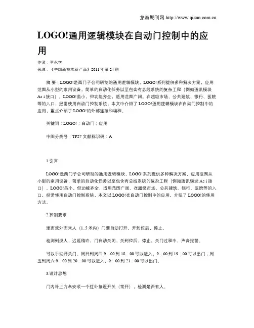
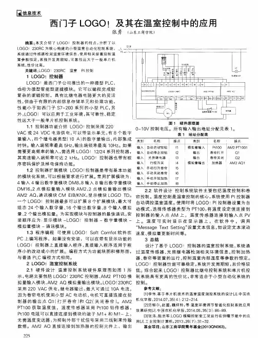
LOGO!通用逻辑模块在自动门控制中的应用作者:李永学来源:《中国新技术新产品》2011年第24期摘要:LOGO!是西门子公司研制的通用逻辑模块,LOGO!系列提供多种解决方案,应用范围从小型的家用设备,简单的自动化任务以至包含有总线系统的复杂工程(例如通讯模块As-i接口)。
LOGO!虽小,但功能齐全,适用范围广阔。
在超级市场、公共建筑、银行、医院等的入口,经常使用自动门控制系统,本文中介绍了LOGO!通用逻辑模块在自动门控制中的应用,重点介绍了LOGO!的外部连接和编程。
关键词:LOGO!;自动门;应用中图分类号:TP27 文献标识码:A1.引言LOGO!是西门子公司研制的通用逻辑模块,LOGO!系列提供多种解决方案,应用范围从小型的家用设备,简单的自动化任务以至包含有总线系统的复杂工程(例如通讯模块As-i接口)。
LOGO!虽小,但功能齐全,适用范围广阔。
在超级市场、公共建筑、银行、医院等的入口,经常使用自动门控制系统,本文以LOGO!在自动门控制中的应用,介绍了LOGO!的使用方法。
2.控制要求里面或外面来人(1..5米内)门要自动打开,开到位后,停止。
检测到没人,迟延稍许,门自动关闭,关到位后,停止,关门过程中,声音报警。
可以手动开关门。
周日到周四9:00到18:00可以进入,9:00到19:00可以出门;周五到周六9:00到20:00可以进入,9:00到21:00可以出门。
3.设计思想门内外上方各安装一个红外接近开关(常开),检测是否有人。
开门到位处、关门到位处安装开门限位开关(常闭)和关门限位开关(常闭)。
用一个切换开关(两个位置:自动、手动)来进行控制方式切换,另一个切换开关(两个位置:投入、停用)来进行投入、停用切换,停用位置兼作紧急停止位置,紧急时,可以让门立即停下来。
另用两个按钮作为手动开门和关门按钮。
开关门的电动机由开门接触器和关门接触器控制,关门时由蜂鸣器发出声音报警。
LOGO! 手册2003年6月版本LOGOi前言尊敬的客户:感谢您购买LOGO!产品,同时对您的明智决策表示祝贺。
您所得到的LOGO! 符合ISO9001严格的质量要求,是值得信赖的产品。
LOGO! 应用非常广泛,功能强、易于操作,在任何实际应用领域中,LOGO! 都具有很高的性能价格比。
本手册的宗旨LOGO! 手册提供您关于建立线路程序,关于安装和使用LOGO! OBA4新系列及其扩展模块,以及和其以前的产品OBA0-OBA3型号(OBAX是订货号的最后4个字符,用以区别设备系列)兼容性等信息。
LOGO!在信息技术(IT)中的位置在LOGO! 手册中接线信息也能在所有包含设备中的LOGO! 产品信息中找到。
关于在PC机上对LOGO! 进行编程的更多信息,可通过PC机中LOGO! 轻松软件(LOGO! SoftComfort)的在线帮助获得。
LOGO! 轻松软件是用于PC机上的编程软件。
它可以运行于Windows®,Linux®,MacOS X®等环境。
它帮助您了解和启动LOGO!,并可独立于LOGO! 对程序进行编制,测试、打印和归档。
本手册使用指南本手册共分9章:• 了解 LOGO!• LOGO! 的安装和接线• LOGO! 的编程• LOGO! 的功能• 组态LOGO!• LOGO! 程序模块(卡)• LOGO! 软件• 应用• 附录本手册的有效范围本手册适用于OBA4系列的LOGO!i前言ii 与以前发布的手册比较,增加了以下的内容:•增加了LOGO! 24o •增加了数字量模块LOGO! DM 8 24R •增加了模拟量模块LOGO! AM 2 PT100 • 描述所作的改变和OBA4系列的新特点与以前的系列(OBA0到OBA3)相比较,其主要优点为:• 更优越的性能;更快的执行时间• 存储容量更大的新程序模块(卡),能保护程序机密,以及可选择的参数• 带背景光的显示和4 x 12个字符推出的OBA4系列的新特点:•提供130个用于建立线路程序的块 •对时间功能还可以选择保持功能 •可使用LOGO! 光标键作输入 •可使用“移位寄存器”、“模拟量放大器”、“模拟量值监控”和“模拟量差值触发器”等专用功能 •可反相每个输入 •基本功能中的6个可通过4个输入进行扩展 •可使用PC 机在线测试线路程序 •某些功能的参数还能从模拟量值和计数器值导出 •对计数器还能使用快速输入(I5,I6)附加的支持 通过我们的Internet 地址:/logo您可以快速、方便地找到您所咨询的问题有关LOGO! 的答案您还能从以下联系信息获得技术支持:电话:+49(0)180 5050-222传真:+49(0)180 5050-223电子邮件:adsupport@德国电话:+49(0)180 5050-222传真:+49(0)180 5050-223电子邮件:adsupport@中国北京 电话:010-64719990传真:010-64719991电子邮件:adscs.china@上海:021-58795255广州:020-87323967成都:028-86200939大连:0411-3699760-40前言iii安全导则在本用户手册中的注意事项是为了您本人的生命安全和避免损坏财产。
111西门子LOGO !自动打铃控制系统王浩然(辽宁工程职业学院,辽宁 铁岭 112000)摘 要:随着时代的发展,目前的打铃系统多种多样,如多媒体中控系统、音乐电铃以及打铃器控制的电铃等,针对学院的实际情况,我们从经济性、可靠性以及操作难易程度上选择了PLC控制的打铃系统,本文主要介绍PLC控制的打铃系统的优点及系统组成。
关键词:学院;LOGO!;打铃一、PLC打铃控制系统的优点(一)经济性。
PLC即可编程序控制器,本系统我们选择的PLC是西门子公司生产的LOGO!控制器。
LOGO!是西门子公司生产的小型PLC。
LOGO!的全球唯一生产基地在中国南京,中国制造却发往世界各地,所以中国客户拿到的产品就代表着全球质量水准。
本地化生产给中国客户带来的就是更短的订货周期、更快的售后服务响应。
相比其他类型的PLC,LOGO!从选型到编程都力求精简,对用户的技术要求最低,而且相对中国市场主流的PLC价格更低,更加经济。
(二)可靠性。
因为PLC采用了大规模集成电路设计,不需要大量的活动元件和连线电子元件,它的连线大大减少。
与此同时PLC采用了一系列可靠性设计的方法进行设计。
例如冗余设计、断电保护、故障诊断和信息保护及恢复。
它具有比通用计算机控制更简单的编程语言和更可靠的硬件。
(三)操作简单。
本系统选用的西门子LOGO!集成了多功能显示面板,我们可以通过面板和组合按键来实现参数修改、系统监控、时钟调整等功能。
而普通类型的PLC及其他打铃系统则必须通过编程软件或专用的多媒体软件来实现。
(四)容易扩展。
西门子LOGO!的输入点可以针对打铃的控制方案来选取,比如日常打铃可以通过一路输入控制,当有考试时可以换另一路输入。
这样就可以通过选取输入点来控制输出,从而实现不同打铃方案快速切换。
如需要临时添加打铃方案,还可通过增加输入点来实现,操作简单,易于扩展。
二、系统组成针对以上优点,我们设计了以LOGO!为控制单元的打铃系统,本系统主要包括CPU模块(西门子LOGO!)、输入、输出模块、控制箱以及软件设计等几部分。
基于西门子LOGO!的洗衣机自动控制系统设计武永红张福顺杜立江(北京铁路电气化学校铁道电气化专业科,北京,102202)摘要:西门子LOGO!是介于PLC和继电器之间的可编程逻辑控制器,它适应控制技术市场细分的趋势,简单灵活,易于设计、维护。
本文采用西门子LOGO!作为全自动洗衣机的控制器,对整个系统进行了创造性的设计,方便了职业教育的控制技术教学,也为LOGO!步入洗衣机控制领域做出了有益的尝试。
关键词:西门子LOGO! 洗衣机自动控制设计LOGO!即可编程逻辑控制器。
它不同于PLC,不具备数学运算功能,但它本身集成了编程能力,且其带负载能力非常强,继电器输出的LOGO!,无须中间继电器与接触器,就可直接接入负载;它也不是继电器,其内部集成了多种继电器功能,外部接线极其简单。
它填补了继电器与PLC之间的技术空间。
随着控制技术市场日益细分,它以简单灵活,易于设计,易于维护逐渐赢得青睐。
为了适应日益细分的技术市场,我们整和现有设备,设计了基于西门子LOGO!的洗衣机自动控制系统,方便今后的控制技术教学,同时,也为LOGO! 创新性地进入全自动洗衣机的控制领域提供了技术参考。
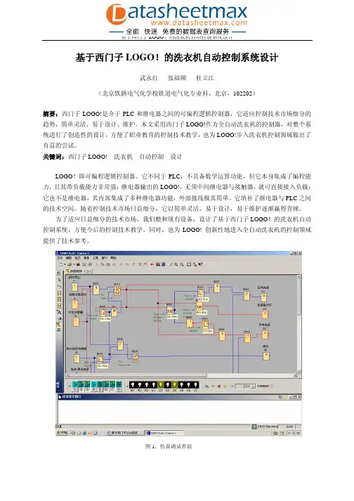
图1.仿真调试界面1、系统总体方案设计概述本系统是在现有设备基础上,进行的改造性设计。
传统的洗衣机采用单片机控制,控制稳定,效率高,LOGO!虽然不如单片机功能强大,但是LOGO!的控制系统更加灵活简便。
在该系统中,我们采用LOGO!做为控制器,选用LOGO!230RC 。
洗衣机我们选用的是现有的海尔宁静型XQB45-A 全自动洗衣机,在拆除系统的单片机之后,保留电机、选择按键等其他设备部件。
按照LOGO!的接线方式设计解决方案,根据硬件电路,把LOGO! 接入洗衣机的基本电路中,完成电路搭建。
此外,由于LOGO!直接由交流220V 电源供电,所以,本系统就不同于单片机,不需要另设直流电源。
在搭建系统的过程中,我们采用LOGO!的配套编程软件在PC 机上开发控制系统程序,并进行仿真调试。
基于西门子LOGO!的真空泵自动控制系统设计摘要本文基于西门子LOGO!控制系统,设计了一种真空泵自动控制系统。
系统由真空泵、空气压缩机、压力传感器、液晶显示屏、西门子LOGO!控制器等部件组成,实现了对真空泵的自动控制和监测。
本文详细阐述了系统的设计思路、硬件连接和程序设计等内容。
实验表明,该控制系统能够实现精确的真空泵控制和运行状态监测,具有较好的实用性和可靠性。
AbstractKeywords: Siemens LOGO!; Vacuum pump; Automatic control; Pressure sensor一、引言随着科技的日益进步,真空技术在工业生产、航空航天、医疗卫生等领域的应用越来越广泛。
真空泵是实现真空技术的关键设备之一,对其的控制和监测显得尤为重要。
目前,大部分真空泵的控制和监测还是采用人工操作的方式,存在着操作不便、控制精度低、实时监测不足等问题。
因此,需要设计一种能够实现真空泵自动控制和监测的系统,提高真空技术的应用效率和生产效益。
二、系统设计2.1 系统功能本文设计的真空泵自动控制系统主要实现以下功能:1)输入真空泵的目标压力值。
2)自动控制真空泵的启停,使其保持在目标压力范围内工作。
3)实时监测真空泵的运行状态,包括压力值和运行时间等。
4)通过液晶显示屏显示真空泵的运行状态和参数信息。
5)实现对真空泵的远程控制和维护,便于实际应用。
本系统采用以下硬件组成:1)真空泵:负责提供真空环境。
2)空气压缩机:用来驱动真空泵工作,保证其不间断连续运行。
3)压力传感器:用来检测真空泵的压力值,并将检测结果传输给控制器。
5)Siemens LOGO!控制器:根据压力传感器的检测结果和用户设置的目标压力值,自动控制真空泵的启停,控制液晶显示屏的显示内容等。
6)其他电气元器件:包括继电器、开关、线路等,用于连接各个硬件之间的电气信号。
2.3 系统设计思路系统的主要设计思路如下:2)用户通过液晶显示屏设置真空泵的目标压力值。
基于西门子LOGO!的真空泵自动控制系统设计作者:户振峰来源:《科学导报·科学工程与电力》2019年第12期【摘要】西门子LOGO!是介于继电器和PLC之间的可编程逻辑控制器,它简单灵活,易于设计、维护。
本文采用西门子LOGO!作为真空泵自动控制系统的控制器,对海普赛能源科技公司原来真空控制系统进行了改造设计。
阐述了其控制原理、特点,在实际应用中的可靠性和优越性。
同时对在安装调试、维护使用中应注意的问题提出了有益的建议。
【关键词】真空泵;西门子LOGO!;可靠性0引言在锂电电池等制造行业,烤箱、搅拌机、自动注液机、封口机等设备必须在真空状态下运行,一旦真空系统出现故障,不仅只是维修真空泵的问题,而且生产无法进行,直接损失巨大,因此保证真空系统包括其控制系统运行的可靠性至关重要。
LOGO!即可编程逻辑控制器。
它不同于PLC,不具备数学运算功能,但它本身集成了编程能力,且其带负载能力非常强,只要选对型号,无须中间继电器和交流接触器,就可直接接入负载;它也不是继电器,其内部集成了多种继电器功能,外部接线极其简单。
它填补了继电器和PLC之间的技术空间。
以简单灵活、易于设计、易于维护逐渐赢得青睐。
1 控制系统的构成1.1基于西门子LOGO!控制的设计思想环宇集团海普赛能源科技有限公司真空系统由两台真空泵组成,原来的电气控制柜是继电器控制,各种继电器合计十余个。
由于继电器触点容易接触不良,时常出现故障,因此必须进行改造,原先准备改用PLC进行控制,这样可用软件代替大量继电器,只要程序写好,故障率会大大下降。
但是PLC各输入、输出端硬件接线线路都要经过公共输入、输出端,接线很不方便,同时PLC动辄几千元或以上,价格不菲,这就造成原料成本和安装成本很高,可是LOGO!市场价格才几百元,并且各输入点只要取自同一相电源即可,而输出又是继电器触点,没有公共端,这在硬件设计上相当自由。
在软件编程上又可将故障状态编成文本显示在显示面板上,并且给出输出报警。
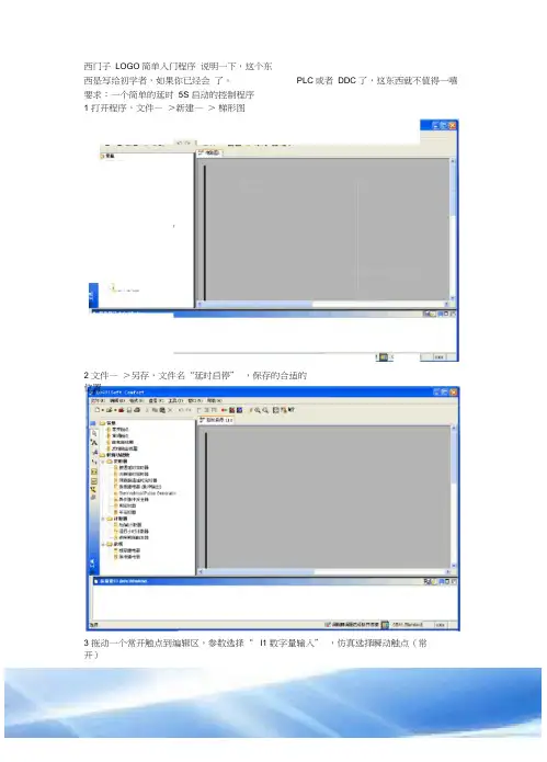
西门子LOGO简单入门程序说明一下,这个东
西是写给初学者,如果你已经会了。
要求:一个简单的延时5S 启动的控制程序
1 打开程序,文件—>新建—>梯形图
2 文件—>另存,文件名“延时启停” ,保存的合适的
位置
3 拖动一个常开触点到编辑区,参数选择“I1 数字量输入” ,仿真选择瞬动触点(常
开)
PLC或者DDC 了,这东西就不值得一嘻
4 同样拖动I2,仿真设置同I1
5 拖动“锁存继电器” ,不用设置参
数
6 拖动常开触点,参数设置“ SF01 锁存继电器”
5S 7 拖动接通延时继电器,双击模块设定参
数
8 拖动常开触点,参数选择TO2 接通延时继电器
9 拖动继电器线圈,参数选Q1 输出
10 连线,单击右键,选择连线,按图连
接
11 仿真,工具—>仿真,可操作下侧开关,查看线路运行情况
另附一个PI 控制图,这个是用的功能块图编写的,仿真时的截图。
《工业控制计算机》2009年22卷第2期摘要西门子LOGO选是介于PLC和继电器之间的可编程逻辑控制器,它适应控制技术市场细分的趋势,简单灵活,易于设计、维护。
采用西门子LOGO选作为全自动洗衣机的控制器,对整个系统进行了创造性的设计,方便了职业教育的控制技术教学,也为LOGO选步入洗衣机控制领域做出了有益的尝试。
关键词:西门子LOGO选,洗衣机,自动控制,设计AbstractSiemens LOGO选is a program controller between PLC and relay.Its advent is a response to the trend of market subdi-vision in the realm of control technology.It is easy to design for the system,simple to use and maintain.In the system, Siemens LOGO选is adopted for the controller of automatic washing machine and a creative design is completed.The new system is not only convenient to the control technology teaching for the vocational education,but also it makes helpful at-tempt that Siemens LOGO选is applied in the industry of automatic washing machine for the controller.Keywords:Siemens LOGO选,washing machine,automatic control,design为了适应日益细分的技术市场,我们整合现有设备,设计了基于西门子LOGO!的洗衣机自动控制系统,方便今后的控制技术教学,同时也为LOGO选创新性地进入全自动洗衣机的控制领域提供了技术参考。
基于西门子LOGO!的水族箱控制系统设计作者:黄桂萍唐张维赖振达吴素华来源:《无线互联科技》2019年第20期摘; ;要:以西门子LOGO!控制器为控制核心的水族箱控制系统具有自动投食、自动换水等功能,同时对液位检测、温度及水质进行实时监测,并具备通信功能,能够与触摸屏、Web Server、手机APP等组建局域网络,该系统设有HMI,可方便进行参数设置及对水环境数据的查询与监控,使得整个系统更加自动化、集成化。
文章对此进行了分析。
关键词:LOGO!;人机接口;网页服务器;手机软件1; ; 新型水族箱提出背景随着我国经济的发展和人民生活水平的大幅提高,人们的消费观念逐渐发生变化,观赏鱼水族箱这个舶来品也开始走进人们的生活当中。
随着人们消费档次与水平的提高,生活环境更加个性化,与之相关的休闲、居家装饰行业相应地不断蓬勃发展。
家用水族产业规模的年增长率达到13.8%,且有逐年递增的趋势,五花八门的水族箱也随之映入人们的眼帘。
但是这些传统的水族箱都普遍功能单一[1-2],水温、照明、排水及充氧等控制器都较普通,并且种类繁多,功能不统一,用户使用时需投入较高费用,安装繁琐,使用复杂,无法提高整体性能,且大多都是非智能化的控制器[3],需要人们投入大量精力去管理水族箱,它们的价格有的较贵,结构复杂,性能不稳定,容易损坏。
随着人工智能的高速发展,本文提出了一款以西门子LOGO!控制器为控制核心的新型水族箱[4-5],采用西门子LOGO!来控制电磁阀、水泵、加热器、增氧泵、灯光,并通过温度传感器、液位传感器实时反馈水族箱里的信息,从而实现智能控制[6-7],其控制系统具有自动化程序高、通信功能强、节能环保3大优点。
2; ; 系统总体设计水族箱控制系统由24 V/5 V开关电源提供所有电力能源,以西门子LOGO!24RCE为核心控制器,液位传感器、温度传感器、pH检测传感器作为数据采集器采集关键参数,并通过触摸屏、Web Server功能、手机APP来实时监控水族箱内各执行部件,如电磁阀、循环泵、加热器、增氧泵、灯光等。
基于LOGO!的全自动洗衣机控制系统设计佚名【摘要】Automatic washing machine is normally controlled by micro-controller unit,which is complicated in programming and hardware,and is difficult to maintain. If automatic washing machine is controlled byPLC,cost is increased. In order to cut costs,simplify programming and maintain convienently,LOGO!con-troller of SIEMENS was applied in the automatic washing machine. Control system of automatic washing ma-chine is analyzed and designed. The software programs was compiled to implement the control in different laundry modes for bafta,chemical fiber,wool fabric at different temperature,and in the modes of single washing,single rinse and dehydration. Frequency converter was used to adjust the speed of dehydration to make the process smooth and steady. The simulation debugging and validation on the control system were made. The results show that the LOGO!can realize all kinds of control functions of automatic washing ma-chine.%针对全自动洗衣机控制系统采用单片机控制存在编程复杂、硬件复杂、维修困难以及采用PLC控制成本高等问题,提出在全自动洗衣机中采用西门子LOGO!控制器。
西门子LOGO!在自动化专业实验教学中的应用与探索【摘要】西门子LOGO!是一款用于自动化控制的软件平台,在自动化专业实验教学中具有重要的应用价值。
本文通过对西门子LOGO!在自动化专业实验教学中的现状分析、特点与优势、具体应用案例的探讨,揭示了其在教学中的实际效果和优势。
本文还对西门子LOGO!在未来发展方向进行了探索,指出了其所面临的挑战和可能的解决方案。
通过对西门子LOGO!在自动化专业实验教学中的重要性和展望未来的讨论,展示了它在培养学生实际操作能力和解决问题能力方面的巨大潜力,为自动化专业实验教学的发展提供了新的思路和方向。
【关键词】西门子LOGO!、自动化专业、实验教学、应用与探索、现状分析、特点、优势、应用案例、未来发展方向、挑战、解决方案、重要性、展望未来1. 引言1.1 背景介绍自动化技术在现代社会中发挥着越来越重要的作用,自动化专业的教育也变得愈发重要。
而实验教学作为自动化专业中不可或缺的一部分,对学生的综合能力培养起着至关重要的作用。
随着科技的不断发展,越来越多的实验教学平台被引入到自动化专业的教学中,以提升学生的学习效果和实践能力。
本文将重点探讨西门子LOGO!在自动化专业实验教学中的应用与探索,分析其现状并探讨未来的发展方向,以期能够为自动化专业实验教学的改进提供参考和借鉴。
1.2 研究意义自动化技术在当今社会发展中扮演着越来越重要的角色,而实验教学是培养学生实践能力和创新思维的重要途径。
研究如何更好地应用西门子LOGO!在自动化专业实验教学中具有重要的意义。
随着工业4.0时代的到来,自动化技术的应用领域越来越广泛,对相关专业人才的需求也在不断增长。
加强西门子LOGO!在自动化专业实验教学中的应用与探索,有助于培养更多符合市场需求的高素质自动化专业人才,推动相关产业的发展。
探索西门子LOGO!在实验教学中的创新应用方法,还可以为教育教学领域的发展提供借鉴和参考,推动实践教学的改革与创新。
基于西门子LOGO!的洗衣机自动控制系统设计
武永红;张福顺;杜立江;王建立
【期刊名称】《工业控制计算机》
【年(卷),期】2009(22)2
【摘要】西门子LOGO!是介于PLC和继电器之间的可编程逻辑控制器,它适应控制技术市场细分的趋势,简单灵活,易于设计、维护.采用西门子LOGO!作为全自动洗衣机的控制器,对整个系统进行了创造性的设计,方便了职业教育的控制技术教学,也为LOGO!步入洗衣机控制领域做出了有益的尝试.
【总页数】2页(P89-90)
【作者】武永红;张福顺;杜立江;王建立
【作者单位】北京铁路电气化学校铁道电气化系,科,北京,102202;北京铁路电气化学校铁道电气化系,科,北京,102202;北京铁路电气化学校铁道电气化系,科,北京,102202;北京铁路电气化学校铁道电气化系,科,北京,102202
【正文语种】中文
【中图分类】TP3
【相关文献】
1.基于LOGO!控制的建筑消防给水自动控制系统设计 [J], 马振峰;姜广坤
2.基于西门子S7-200和组态王6.53的洗衣机监控系统设计 [J], 张红娟;姜波
3.基于西门子LOGO!的海洋钻井平台固井空压机控制系统设计 [J], 王伦;符新涛;李文磊;陈尚广
4.基于LOGO!的全自动洗衣机控制系统设计 [J],
5.基于西门子LOGO!的水族箱控制系统设计 [J], 黄桂萍; 唐张维; 赖振达; 吴素华因版权原因,仅展示原文概要,查看原文内容请购买。