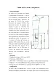
HDPE反应器R6300吊装方案 B
- 格式:doc
- 大小:10.66 MB
- 文档页数:23
hdpe施工方案HDPE(High Density Polyethylene)即高密度聚乙烯,是一种热塑性材料,具有优异的机械性能和耐化学腐蚀性,广泛应用于各种工程领域。
下面是一个HDPE施工方案的简要描述,总共约700字。
一、施工准备1. 准备材料:HDPE料、焊接机、管件等。
2. 清理施工现场:将施工现场清理干净,确保平整无障碍,清除任何可能影响施工的杂物。
3. 建立施工档案:记录施工过程中的关键信息,包括工程名称、施工日期、施工人员等。
二、施工工艺1. 编制详细的施工方案:根据设计图纸和相关规范,编制施工方案,并与相关人员进行沟通。
2. 确定施工顺序:根据施工方案确定施工顺序,包括管道的安装、焊接、连接等。
3. 确保安全:在进行任何施工操作前,必须确保工作场所安全,并采取必要的安全措施,如佩戴个人防护设备、设置示警标志等。
4. 管道安装:根据设计要求,将HDPE管道进行准确定位和定位,确保管道的安装位置准确无误。
5. 管道焊接:使用焊接机进行焊接,保证焊接接头牢固可靠,焊接质量符合规范要求。
6. 管道连接:使用相应的管件进行连接,确保连接紧密、密封可靠。
7. 管道测试:完成管道焊接和连接后,进行相应的压力测试和漏水测试,确保管道的完整性和可靠性。
8. 质量检查:进行质量检查,确保施工质量符合相关标准和规范。
9. 施工记录:及时记录施工过程中发生的重要事项,包括焊接参数、检测结果等。
三、施工要点1. 保持施工现场的清洁,避免杂物对施工造成干扰。
2. 严格按照规范要求进行焊接,确保焊接接头质量可靠。
3. 在进行压力测试和漏水测试时,确保测试过程中的安全,避免意外发生。
4. 在施工过程中,如遇到无法解决的问题,及时与设计人员和相关专业人员沟通。
四、施工注意事项1. 遵守相关安全规范和操作规程,确保工作场所的安全。
2. 严格按照设计要求和施工方案进行施工,确保施工质量符合规范。
3. 在施工过程中注意环境保护,避免对周围环境造成污染。
CSPC NANHAI PETROCHEMICALS PROJECT
中海壳牌南海石化项目
R6300反应器吊装工作安全分析
JSA FOR R6300 REACTOR LIFTING
NH-HDPE+PP-HSE-JSA-009 RevB
2 of 6 中油六建惠州项目HSE 部R6300反应器吊装工作安全分析JSA FOR R6300 REACTOR LIFTING HuiZhou Proj. HSE Dept. of CP6CC
NH-HDPE+PP-HSE-JSA-009 RevB 3 of 6 中油六建惠州项目HSE部
R6300反应器吊装工作安全分析JSA FOR R6300 REACTOR LIFTING HuiZhou Proj. HSE Dept. of CP6CC
NH-HDPE+PP-HSE-JSA-009 RevB
4 of 6 中油六建惠州项目HSE 部R6300反应器吊装工作安全分析JSA FOR R6300 REACTOR LIFTING HuiZhou Proj. HSE Dept. of CP6CC
NH-HDPE+PP-HSE-JSA-009 RevB 5 of 6 中油六建惠州项目HSE部
R6300反应器吊装工作安全分析JSA FOR R6300 REACTOR LIFTING HuiZhou Proj. HSE Dept. of CP6CC
NH-HDPE+PP-HSE-JSA-009 RevB 6 of 6 中油六建惠州项目HSE部
R6300反应器吊装工作安全分析JSA FOR R6300 REACTOR LIFTING HuiZhou Proj. HSE Dept. of CP6CC。
HDPE管安装专项 施工方案中国水利水电******有限公司南昌市*********************项目部2013年12月一、工程简介南昌市***工程主要位于**********工程涉及HDPE截污管33.4km。
二、参照规范1、《给排水管道工程施工及验收规范》(GB50268-2008)2、《埋地聚乙烯排水管道工程技术规程》(CECS164:2004)3、《埋地排水聚乙烯(PE)结构壁管道系统》(GB/T19472.2-2004)三、施工流程HDPE管施工流程如图1所示。
四、施工准备4.1管道装卸与存放1、管道主要采用机械装卸,装卸时应采用柔韧性好的皮带、吊带或吊绳进行吊装,不得采用钢丝绳或链条进行装卸和运输。
2、管道装卸时应采用两个支撑点,两个支撑点位置宜放在管长的四分之一处,以保持管道稳定。
3、在管道装卸过程中应防止管道撞击或摔跌,尤其注意对管端承插口的保护,如有擦伤应及时与厂家联系,以便妥善处理。
4、管道直接放在地上时,要求地面平整,不能有石块和容易引起管道损坏的尖利物体,要有防止管道滚动的措施。
5、不同管径的管道堆放时,应把大而重的放下边,轻的放上边,管道两侧用木板挡住。
堆放时注意底层管道的承重能力,堆放高度不超过3米。
4.2管道进场检测1、运到现场的管道,先查验出厂合格证及出厂检测报告。
现场可采用目测法对管道是否有损伤进行检验,同时做好记录与验收手续。
2、如发现管道有损伤,应及时进行标记并分开存放,同时通知厂家驻地工程师进行检查鉴定,不合格的进入不合格品处理程序。
图1 HDPE管施工流程图3、每一批次及时进行现场取样检测,通知监理工程师现场见证,样品应随机抽取,取样数量与长度应符合规范及实验要求。
五、沟槽的开挖1、沟槽开挖时,开挖坡度应按设计图纸或已经经监理工程师批复的施工方案进行。
2、管道沟槽底部开挖宽度应设计要求进行,设计无要求时,可按下式计算:B=D0+2(b1+b2)+b3 式中:D0-管道结构外径管道吊装 现场取样b1-管道一侧工作面宽度,可按下表进行取值b2-管道一侧的支撑厚度,可以取15-20cm ,没有支撑时取b2=0 b3-沟槽底部排水沟宽度,可取b3=50cm管道一侧工作面宽度管道外径D0(mm)最小一侧工作面宽度b1(mm)D0≤500 300 500<D0≤1000 400 1000<D0≤1500 500 1500<D0≤30007003、 开挖沟槽时,槽底设计标高以上0.2-0.3m 原状土应给予保留,铺管前用人工清理,但一般不宜挖至沟底设计标高以下,如局部超挖,需用沙土或原土填补并分层夯实。

反应器吊装施工方案编制人:审核:审定:部门会签:批准:目录1、编制说明 02、编制依据和执行规范 03、工程概况和特点 03.1 工程概况 03.2 工程特点 04、吊车选择及使用计划 (1)4.1 吊车选择 (1)4.2 吊车使用计划 (1)5、加氢反应器吊装 (1)5.1 方案编制依据 (1)5.2 具体施工工艺 (2)5.3 吊装过程说明 (2)5.4 吊车绳索具 (4)5.5 吊装工艺及吊车抗杆计算 (5)6、吊装过程力学分析 (7)6.1 主吊车与溜尾吊车初始提升力计算 (7)6.2 吊耳设计校核 (8)6.3 裙座加固处理 (11)7、地基处理及地耐力计算 (12)7.1 地基处理依据 (12)7.2 主吊车对地面压力计算 (12)7.3 溜尾吊车400T汽车吊车作业时地基受力分析 (13)7.4 总结及地面处理范围 (14)7.5 地基处理程序及要求 (14)7.6 井、地下管的保护措施 (14)8、大型设备吊装施工管理组织体系和操作人员岗位职责 (15)8.1 大型设备吊装组织体系图 (15)8.2 设备吊装岗位职责 (16)9、QHSE管理 (17)9.1 吊装安全质量保证体系岗位职责 (17)9.2 安全技术要求 (18)9.3 JHA危害分析以及安全对策表 (19)10、吊装施工用主要施工机索具及手段用料一览表 (25)11、附录吊盖计算 (26)1、编制说明本吊装施工方案主要针对XXXXXXXXXXXXXXXXXXXXXXXXXXXXXXXXXXXXXX吊装施工。
本方案涉及的设备参数依据本工程项目设计及施工图。
本方案是目前依据业主提供的设备整体供货信息而编制的,若设备实际到货情况与本方案不符时,另行编制修订方案或补充方案。
2、编制依据和执行规范国家(行业)有关标准、规范:—《起重机械安全规程》GB6067-2010—《建筑地基基础设计规范》 GB50007-2002—《大型设备吊装工程施工工艺标准》 SH/T3515-2003—《石油化工工程起重施工规范》SH/T3536-2002—《大型设备吊装安全规程》SY6279-2008—《工程建设安装工程起重施工规范》 HG20201-2000—《化工设备吊耳及工程技术要求》 HG/T21574-2008—300万吨/年柴油加氢装置平面布置图—加氢精制反应器R101设计蓝图—利勃海尔LR1750履带吊车性能表—利勃海尔LTM1400型汽车吊车性能表—神钢CLK2600履带吊车性能表3、工程概况和特点3.1 工程概况XXXXXXXXXXXXXXXXXXXXXXXXXXXXXXXXXXXXXXXXXXXXXXXXXXXXXXXXXXXXXXXXXXXXXXXXX XXXXXXXXXXXXXXXXXXXXXXXXXXXXXXXXXXXXXXXXXXXXXXXXXXXXXXXXXXXXXXXXXXXXXXXXX XXXXXXXXXXXXXXXXXXXXXXXXXXXXXXXXXXXXXXXXXXXXXXXXXXXXXXXXXXXXXXXX3.2 工程特点(1)设备吊装重量大,对吊装的要求较高。
CONTENTS1. SCOPE2. REFERRENCE DOCUMENTS3. PIPING QUALITY REQUIREMENT & QUALITY INSPECTION PROCEDURE4. CONSTRUCTION PREPARATION5. PIPING PREFABRICATION & INSTALLATION6. PIPING HYDROTEST7. PIPING CLEAN AND REINSTALL8. CONSTRUCTION HSE REQUIREMENT9. REVISION1. SCOPEThis PLAN applies for CSPC NANHAI PETROCHEMICAL PROJECT HDPE UNIT RX-6300 CYCLE GAS PIPING prefabrication, installation, inspection, test, purging, and etc.2. REFERRENCE DOCUMENTS2.1 R6300-CYCLE GAS SPECIFICATION-HDPE(DS-PB01-TMOC-0901 REV.00)2.2 RX6300 COLD PULL PROCEDURE (SP-8230-TMOC-0120)2.3 FCN-PI-0070 (3163-LE-TIST/CP6CC-2937)2.4 DIMESIONAL SPECIFICATION BOLTS FOR FLANGED CONNECTIONS R6300(RECYCLE GAS) (DS-PB01-TMOC-0800 REV. A)2.5 SHOP AND FIELD FABRICATION OF PIPING (DEP 31.38.01.31-CSPC)2.6 BOLT TENSIONING AND FLANGE BOLT-UP REQUIREMENTS (P1-8130-TEC1-0002)2.7 CONSTRUCTION DRAWINGS FOR STD ELEMENTS (58-8230-TMOC-0106)2.8 PIPING PRESSURE TEST BLIND SELECTION & DESIGN (PETROLEUM PROJECTCONSTRUCTION, No1ST, 29TH VOLUME)2.9 INDUSTRIAL METAL LIC PIPING PROJECT CONSTRUCTION & ACCEPTANCE CODE(GB50236-98)2.10 INDUSTRIAL PIPING WELD CONSTRUCTIONN & ACCEPTANCE CODE (GB50236-98) 2.11 PETROCHEMICAL TOXIC, FLAMMABLE MEDIUM PIPING CONSTRUCTION &ACCEPTANCE CODE (SH3501-2002)2.12 PIPING FIELD PRESSURE TESTING (PR-8330-TECI-0002, REV2)3. PIPING QUALITY REQUIREMENT & QUALITY INSPECTION PROCEDURE3.1 Quality requirement accords with design document, vendor document and relevant technicalspecification & code.3.1.1 For surface treatmenta. All internal welds to be ground smooth and level with plate surface;b. Internal areas of nozzles, including inner face of displacer where applicable, to beground smooth without steps or ridges, and contoured to pipe internal wall radius.3.1.2 For mechanical completion of pipe system after hydro-test finished.a. Each spool must be checked for internal smoothness and cleanliness.b. No surface rust scale, indentations, ridges, weld spatter, grooves etc. is allowed. Anyoil, wax or surface protection coatings (e.g. from roll mill) must be removed.c. The whole internal area of the pipe must be completely clean.3.1.3 NDT inspection. To perform 100% RT for all annular welds, the quality grade shall notlower than Ⅱ; perform 100% MT for all fillet welds, the quality grade shall not lower than Ⅱ. All rejected welds must be reworked up to acceptance.3.1.4 When dismantle R-6300 top & bottom blind for pipe installation, the installation work mustcomplete as soon as possible. Once pipe installation completion, fill in N2 to R-6300 timely.3.2 Quality inspection procedure.a. Dismantle & lift down the pipe to the ground, internal welds to be grinded smooth andlevel with internal surface, and clean.b. Submit Inspection Request, inform TISA/BSF to check.c. NDT check.d. Hydro-test.e. Clean pipe internal surface, ensure the cleanliness.f. Submit Inspection Request, inform TISA/BSF to check pipe internal cleanliness beforespool reinstatement (if the spool pass hydro-test and has to put on the ground for a longer time, the ends of the spool shall be blinded and fill in with N2).g. To reinstall spool R-6300 top and bottom, the both ends shall start simultaneously.Meanwhile blinds are required to seal the spools, to fill in N2 until the pipe installation completion.4. CONSTRUCTION PREPARATION4.1 Piping material, fittings, components, etc are completely checked & prepared, and also theyshall conform to relevant technical documents and material lists.4.2 Relevant technical specifications, codes, design documents & vendor standards are at hand.4.3 Well Prepare construction equipments, tools, facilities and auxiliary materials. Constructionarea shall be clear and reach construction requirement.4.4 Study construction drawings, design documents, vendor specifications, and installation &acceptance codes. Lifting plan for removal & reinstall shall be prepared.4.5 Work out construction plan and submit for approval.4.6 Prior to commence piping construction, make job safety analysis, refer to JSA.5. PIPING PREFABRICATION & INSTALLATION5.1 Piping prefabrication shall follow with project document and relevant specification.5.2 Piping installation shall follow with project document and relevant specification.5.3 Piping cold pull.As per design documents RX6300 COLD PULL PROCEDURE (SP-8230-TMOC-0120), cold pull installation is required for heat exchanger EA-6321 outlet (T2) spool-3, see attachment-1. To meet with relevant requirement, the construction procedure below shall be strictly followed:a. To measure the central elevation of R-6300 bottom flange nozzle (N2) and EA-6321flange (T2). At the same time, to measure horizontal spool length spool-1, spool-2, see attachment-1)b. To connect flanges on spool -3 to body flange on equipment EA-6321 with bolts.Meanwhile, to insert aδ=20+h(h=height of gasket raising out of flange face) mm thick, 40mm wide annular spacer between two flanges. To adjust flanges concentricity and level, and then tighten the bolts.c. To measure the whole length of horizontal spool -3, elbow and flange actual length.According to the measurement, weld the joint ○A. Ensure to keep uprightness and levelof spool end and flange.d. Successively, complete installation of spools -2 and spool-1. The weld joint ○B onspool-1 is the last joint to be welded on piping 203-PG632004.5.4 After complete the whole piping, submit inspection request, inform TISA/BSF to performwalkdown, to check if the piping installation meets with relevant specification and code requirement.5.5 To rectify and modify the installation problems if any has observed.5.6 After rectification to TISA/BSF’s satisfaction, dismantle the pipe to ground and prepare forhydro-test. Work on the ground shall be completed ASAP.6. PIPING HYDROTEST6.1 Test pressure confirmation. According to TQ-1313 reply, the design pressures are the same of25 bar for compressor K-6330 inlet & outlet pipes 203-PG632001, 203-PG632002,203-PG632003, 203-PG632004, so hydro-test pressure shall be 37.5 bar for RX-6300 cycle gas piping.6.2 Hydro-test classification. Cycle gas piping to be conducted hydro-test by 2(two) groups.Details as follows:6.2.1 The 1st hydro-test includes the following spools and which shall be connected in the orderof spool-10→spool-9→spool-8→spool-7→spool-5→spool-4→spool-3→→spool-2→spool-1. All above spools in this test group must be dismantled to ground and connected together for hydro-test.The 2nd hydro-test includes the spool -6. This spool is unnecessary to be dismantled to ground. It can be directly conduct hydro-test in its installation position. This spool can not be dismantle to ground owing to field space restriction.6.2.2 Weld internal surface grind, clean and check6.3 Dismantle spools to ground.6.4 Then connect the spools as per item 6.2.1. Temporary gasket for hydro-test.6.5 Blind selection for hydro-test (available before perform hydro-test).6.5.1 The ends of spool tested are flanges. What is more, no redundant flanges to match them.So blind flanges for hydro-test must be fabricated by us.6.5.2 The thickness of blind for hydro-test. As per PIPING PRESSURE TEST BLINDSELECTION AND DESIGN (PETROLEUM PROJECT CONSTRUCTION, No1ST, 29TH VOLUME), the thickness of blind used for hydro-test is calculated as follows:δ=0.44Dc (P/[σ]t)1/2+CIn which: Dc----piping design diameter/mm, normally Dc=Di (Di is pipe actual insidediameterP----piping hydro-test pressure/MPa[σ]t ----material tolerance stress/MPa. 20R material [σ]t =130MPa, 16Mnmaterial [σ]t =170MPa, Q235 material [σ]t =120MPaC----blind wall thickness, normally C=1~3mmδ= calculated thickness of blind flange6.6 Piping hydro-test procedure and requirementPiping hydro-test procedure and requirement will be followed with PIPING FIELD PRESSURE TESTING (PR-8330-TECI-0002, REV 2).7. PIPING CLEAN AND REINSTALL7.1 Clean the pipe immediately as soon as hydro-test finished.7.2 To self-check spool internal surface cleanliness, then inform TISA/BSF to check. Checkcontents as the same as Item 3.1.2.7.3 Spool painting and insulation. Solvent used to degrease flange surface. Clean and dry theflanges. Then paint the flange surface (excluding sealing surface) and spool external surface.7.4 Lift and reinstate spool.8. CONSTRUCTION HSE REQUIREMENT8.1 Before commence piping prefabrication and installation, Project HSE Requirement must bestrictly complied with. Wear correct PPE. 100% Tie-off safety harness during high work.8.2 Before dismantle platform, barricade the dangerous area with warning tape to preventirrelevant person from entering. Operator must take good care of himself, be sure 100% Tie-off. Take notice the surrounding risk once the grating and beams removed. If necessary, strengthen the potential risk area.8.3 Barricade the working area when conduct lifting work and hydro-test. Irrelevant person areprohibited from entering.8.4 Prior to lift spool, carefully check lifting tools, sling, to ensure them in good condition. As perconfiguration, height of lifting spool, crane capacity, to estimate lifting reliability.8.5 During hydro-test, when increase or hold pressure, in case leakage observed, never try tosettle the leakage problem. To settle the leakage problem after release pressure only.8.6 In case enter pipe and perform welding, grind, clean or purge, applying and obtainCONFINED SPACE ENTRY PERMIT is a must. Moreover, dedicated watchmen are required.8.7 In case pipes fit up, welding, temporary supports must be firm and credible. Chock used toprevent pipe from slipping/rolling must have adequate height and contact area with ground.Chock shall be put firmly.8.8 Safely make use of power supply during construction. Conform to relevant regulation onpower supply usage.8.9 Violating regulation to work, operate and instruct is whatever never allowed.9. REVISIONIn case this PLAN cannot completely guarantee the completion of this PIPING construction, new construction condition observed, and/or requirement from TISA, the PLAN shall be discussed, supplemented, and revised accordingly.。
Contents1.设备的主要参数General description (2)2.吊装方案的选择Section of lifting scheme (2)3.吊装平面布置Lifting layout (2)4.吊装立面图Lifting elevation (3)5.吊车吊装工况的选用Selection of Operating Condition of the Cranes (4)6.吊车对地面的压力核算Pressure accounting of crane to ground (5)7.吊索具的选用Selection of Slings and Rigging (5)8.安装步骤:The Erection Sequence (6)9. 安全措施Safety Measures (7)10. 所需机具、设备Lifting Equipments and Tools Needed (8)1.设备的主要参数General descriptionV6370 的设备总重量为64t,外形尺寸φ4830×14540mm,如下图所示:The total weight of V6370 is 64t with a outline size of φ3524×25982mm which is shown in the sketch below.V6370安放在距地面有23.25米高的钢结构基础框架上,吊装时要越过42.25米处的钢梁。
所以吊装高度H=42250+500+25982=68732mm。
V6370 is to be placed on a 23.25m high steel frame, and it should go over the steel beam that is 42.25m high. Then the lifting height is H=42250+500+25982=68732mm. 2.吊装方案的选择Section of lifting scheme根据现场的条件及现有的吊装机具,V6370吊装采用单台吊车提升的方法来安装,主吊车选用一台400t履带吊(LR1400型),另外还需用一台50t汽车吊(KATO NK500E型)辅助溜尾。
塑料幕墙吊装方案
1. 引言
本文旨在提供一份塑料幕墙的吊装方案,以保证施工过程的顺
利进行。
塑料幕墙作为一种常用的建筑幕墙材料,在现代建筑中得
到广泛应用。
本方案将介绍吊装所需的设备和步骤,以及注意事项。
2. 设备与工具
- 吊车:具备足够吨位的吊车,用于将塑料幕墙吊装到指定位置。
- 吊装索具:包括起重链条、吊钩、吊具等,用于连接和固定
塑料幕墙。
- 安全带:用于吊装操作人员的安全保护。
- 支撑材料:用于支撑塑料幕墙在吊装过程中的稳定性。
3. 吊装步骤
1. 准备工作:确定吊装位置和吊装高度,并清理好工作区域,
确保安全无障碍。
2. 安装吊装索具:将吊装索具连接到塑料幕墙上,确保牢固可靠。
3. 吊装操作:由吊车操作员操作吊车将塑料幕墙吊装到指定位置,并由其他人员用支撑材料做好支撑工作,以确保塑料幕墙的稳
定性。
4. 安全检查:吊装完成后,进行安全检查,确保塑料幕墙安装
牢固且无安全隐患。
4. 注意事项
1. 在吊装过程中,要严格按照操作规程进行,确保施工安全。
2. 吊装前需检查吊车和吊装索具的工作状态,确保设备正常运行。
3. 吊装操作人员需穿戴好安全带,做好安全防护措施。
4. 吊装过程中,要保持良好的沟通协调,确保操作的顺利进行。
5. 对施工环境和塑料幕墙进行全面检查,排除潜在危险因素。
以上为塑料幕墙吊装方案的概要,详细操作及安全注意事项应
根据实际情况进行制定。
在施工过程中,务必依照相关法律法规和
安全规定进行操作。
HDPE装置施工方案1. 引言本文档旨在为HDPE装置施工方案提供详细的说明和指南。
HDPE是指高密度聚乙烯(High Density Polyethylene)的缩写,它具有优异的耐腐蚀性和高强度,被广泛应用于各种工业领域。
本文将介绍HDPE 装置施工的步骤和注意事项,以确保施工顺利进行。
2. 施工步骤2.1 基础准备在开始施工之前,必须做好基础准备工作。
包括但不限于以下步骤:•清理施工现场,确保没有杂物和障碍物。
•确定施工区域的边界,并进行标记。
•检查工具和设备的完好性,确保其符合安全标准。
•配备必要的安全设备,如安全帽、防护眼镜和手套等。
2.2 安装前的准备工作在正式安装HDPE装置之前,需要进行一些准备工作,以确保施工的顺利进行。
以下是准备工作的步骤:1.绘制设备安装图纸:根据实际情况,制作设备安装的平面图和剖面图,并确保图纸的准确性和完整性。
2.订购和检查材料:根据设备安装图纸,订购所需的HDPE管材和配件等材料,并进行检查以确保其质量符合要求。
3.设备检查和调试:对待安装的HDPE设备进行检查和调试,确保其功能正常并符合设计要求。
2.3 施工步骤根据设计要求和设备安装图纸,进行以下HDPE装置的施工步骤:1.位置定位:根据设备安装图纸,确定HDPE装置的准确位置,并进行标志。
2.材料准备:将所需的HDPE管材和配件等材料按照要求准备齐全,确保其数量和质量符合要求。
3.安装管道:根据设备安装图纸,按照顺序进行HDPE管道的安装。
确保管道之间的连接紧密可靠,并进行必要的密封处理。
4.安装阀门和仪表:根据设计要求,安装HDPE装置所需的阀门和仪表,确保其位置准确、功能正常。
5.系统测试:完成HDPE装置的施工后,对整个系统进行测试,包括压力测试和泄漏测试,以确保系统的稳定性和安全性。
6.清理和整理:施工结束后,清理施工现场,将垃圾和废料进行分类处理,并整理好工具和设备。
7.完工验收:根据设计方案和技术标准进行完工验收,确保HDPE装置的质量和安全性符合要求。
HDPE管道施工方案1.1.1.适用范围适用于室外雨水管道和室外排水管道。
1.1.2.工艺原理HDPE管道安装,采用人工安装。
用非金属绳溜管,使管道放入沟槽,确认胶圈安装位置及插口的插入深度,将承口内壁清理干净,并在胶圈上涂润滑剂,对准中心轴线利用手动葫芦等提力工具逐节依次安装就位。
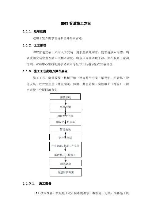
1.1.3.施工工艺流程及操作要点施工工艺:测量放线→机械开槽→槽底整平夯实→铺设中、粗砂基→管道安装→砼井室垫层→井室砌筑、抹面、井室防腐→胸腔填土(稳管)→闭水试验→分层回填夯实1.1.3.1.施工准备(1)技术准备:按照施工设计图纸的要求,编制施工方案,准备施工机械设备。
(2)施工放样:复测控制点及控制网和导线,测放井室位置和管道中心线。
(3)施工便道:合理布置施工便道,与沟槽保证一定的距离,满足施工需要亦不影响槽壁稳定。
(4)管线交底:首先开挖前了解已有管线位置,检查开挖沟槽前地下是否有管线,光缆或其他物体,若有,及时通知工程师及设计代表确认,并协商解决办法,进行妥善处理。
(5)技术(安全)交底:对参与施工的项目管理人员及劳务队进行施工(安全)技术交底。
(6)材料进场:HDPE双壁波纹管施工中的原材料按要求进场。
(7)实验检验:完成原材料检验及混凝土配合比设计及实验等工作。
1.1.3.2.测量方案进场后对设计单位交接的水准点和导线点进行复测,闭合差符合要求后,进行导线点、水准点的加密,加密点必须进行闭合平差,确保加密点的准确,以满足排水管高程,线型控制的精度。
由于井室中桩在施工中要被挖掉,因此在不受施工干扰、易于保护的地方测设施工控制桩,采用延长线法,测设附属构筑物位置控制桩。
施工过程中的测量主要是槽底高程的确定,机械开挖后,采用跟机测量,随挖随测,杜绝超挖现象,确保槽底高程符合设计要求,铺设砂基时,进行复测,发现问题及时处理,使管底高程控制在允许偏差范围内。
每次测量工作开始前,都要进行相邻点的复核测量。
管道中心有井室中心桩来确定,通过控制桩在管道基础上打出边线,确定管道的铺设位置。
HDPE Reactor R6300 Lifting Scheme1. General DescriptionThe outline size of the HDPE reactor R6300is φ7600/φ5000×32765mm with a weight of278.5t, which is to be installed vertically onthe steel structural frame at an elevation onthe ground of ▽+23.25m (the referenceelevation on the ground is ▽+0.00m). Theelevation at the top of the equipment afterinstalled in place is ▽+42.75m. Themaximum elevation at the top of theequipment during lifting operation is ▽+57m.The main lifting lug is located at the flangeface on the top of the equipment, which is aspecial lifting device connected to the flangeface on the top by bolts. The tailing lug is setat a position 2.37m from the bottom of theequipment. Both the main lifting lug and thetailing lug are plate-typed lifting lug of singlelifting point. The center of gravity of theHDPE reactor is at the axis 15.4m from thebottom of the equipment. The outline andSketch1dimension of the reactor R6300 is shown insketch 1.2. References2.1 Equipment drawing of HDPE reactor R63002.2 Plan layout of HDPE/PP plant2.3SH/T 3536——2002 Lifting Construction Specification for Petrochemical Engineering 2.4 SHJ 515——90 Technical Standard for Heavy Equipment Lifting Construction2.5 Design Documents of Climbing Jack System provided by Bidlift Co. Ltd., U.K3. Lifting SchemeThe lifting of the reactor R6300 will be performed with the Kramo climbing jack system introduced from Bidlift Limited, U.K by our company. This system has a maximum liftingcapacity of 2,400t and a maximum lifting height of 140m according to the present configuration of the system we ordered. For this project, only part of the system is needed to perform the lift of the reactor R6300. Therefore, the system is to be used as main lifting gear for the lift of the reactor R6300 and a 400t crawler crane for tailing.The lifting process of the reactor is shown in the following sketches.1. Start Lifting2.Jacks are climbing up while tailing-in crane carries the reactor forwardto vertical position.surface of the foundation.5. The reactor is moved over the foundation by horizontally-moving jacks6. The reactor is lowered in place4. Route for the Equipment Access and Lifting Plan LayoutThe reactor R6300 will be transported to the north side of the foundation along the road on the west side of HDPE/PP plant. After being offloaded, it will be laid as shown in sketch 2 with its top facing west and its end facing east. The plan layout for the lift and the locations of deadman are shown in sketch 3 below.图2Sketch 2Sketch 35. Reactor OffloadingThe offloading of the reactor can be carried out by taking advantage of the hydraulic up-and-down performance of the bogie. The location for laying the reactor shall be leveled and compacted and paved with a 200mm thick layer of gravel. 8 reinforced concrete bearing blocks will be placed before hand for supporting the reactor. The concrete block will be 1.6m×1m×1.2m (L×W×H). These 8 concrete blocks will be arranged in position as shown in sketch 4 prior to the arrival of the reactor to allow access for the bogie to get the midst of the concrete blocks. When the 4 saddles of the reactor are aligned with the concrete blocks, the reactor can be offloaded.Sketch 46.the Lifting System ConfigurationLifting elevation of HDPE reactor R6300 is shown in sketch 5 and sketch 6 below.Sketch 5Sketch 61——Mast Tower2——Lifting Beam3——Climbing Jacks4——Base5——Base Sliding Rail 6—— Swivel 7——Guy Wire System the system components required for the lift of the reactor R6300 are described as follows. 6.1Mast SectionsThe center dimension of the cross section of the mast sections is 2.2m×3m. Altogether 14 sections of 12m long each are needed to build two 84m mast towers.6.2 Lifting BeamThe lifting beam is 18m long with a capacity of 800t.6.3 JacksTwo 400t jacks, each with a power pack.6.4 BaseTwo mast tower bases have a bearing capacity of 1,200t each.6.5 Base Sliding BeamTwo base sliding beams is 15m long each.6.6 SwivelOne set of swivel with a lifting capacity of 800t.6.7 Guy Wire SystemUpper and lower guy wires will be set up. There are 12 guy wires altogether, 6 for upper guy wires and 6 for lower guy wires.6.8 Square Bar28 square bars of 200mm×200mm×6000m each ,8 square bars of 100mm×100mm×3000mm each.6.9 Jacks for horizontal movementThree 100t jacks for horizontal movement, each with a power pack.6.10地锚 DeadmanTwo 60t deadman and four 40t deanman are required.6.11 Control SystemOne set of computer controlled system is to be used.7.有关受力计算 Relevant Force Calculation7.1 Maximum Load Force of the Tailing Crane The tailing crane has the maximum load force when the lifting starts. See sketch 7.图7t G Pa 16063.306.175.27863.306.17=⨯=⨯= One 400t crawler crane will be used for tailing. The operating condition of the crane is: boom length 49m, operating radius 9m. The rated lifting capacity of the crane under thisoperating condition is 204tons, the load percentage is 74.4%, which satisfy the lifting requirement.7.2 Maximum Load of JacksSee sketch 8. During the full process of the lifting operation, the maximum load of the jacks acts on the jacks on the north mast tower, that is the load after the reactor is lifted from the position starting lifting to vertical position. The maximum load P of the jacks is:Sketch 8t Q g G P 2393021185.13)205.278(21185.13)(=⨯+⨯+=+⨯+=where :G ——reactor weight ,G=278.5t g ——weight of swivel and rigging ,g=20t Q ——weight of the beam ,Q=30t 7.3 Load Force on the GroundSee sketch 9. During the whole process of the lifting operation, the maximum compressivestress the ground under the mast section base bears is: (1) maximum compressive stress N360t on the ground under the inner side of the mast tower; (2) maximum compressive stress 64t on the ground under the outer side of the mast tower.图97.4 Tension Force of Guy Wires and DeadmanSee sketch 10 and Sketch 11. By calculation, the maximum tension force of the guy wires in the direction of north-to-south is 28.2t, their deadman horizontal component of forces is 44t while the vertical component of forces is 33.6. The maximum tension force of the guy wires in the direction of west-to-east is 19.8t, their deadman horizontal component of forces is 31t while the vertical component of forces is 23.7t.The calculation of the tension forces of the guy wires and deadman is attached.Sketch 10Sketch 117.5 the Load Force of the Other ComponentsThe calculation of load forces of the other components will not be described in this scheme since the weight of the reactor R6300 is within the design capacity of the lifting system.8. Selection of Rigging8.1 Main RiggingThe maximum tension force of the main rigging is the same as the weight of the HDPE reactor R6300 278.5t. The rigging is made up by connecting in series 2 pieces of 20m in circumference, φ184mm dia. non-joint wire rope loop to three 400t shackles as shown in sketch 12. The break tensile force of a single φ184mm non-joint wire rope loop is 1,800t and its allowable working load is 300t.8.2 Tail RiggingThe maximum tension force of the tail rigging is 160t. The rigging is made up by connecting in series one 16m long, φ104mm dia. pressed wire sling to a 200t shackle. The sling is used bent double as shown in sketch 13. The break tensile force of a single φ104mm sling is 853t and its allowable working load is 142t. The allowable working load increases to 213t when it is used bent double.Sketch 12 Sketch 139.Procedure for the Erection of the Lifting System & the Lifting of the Reactor 9.1 VesselCheck lifting attachments attached securely per specificationCheck lifting shackles fit lifting attachmentsCheck weight of vessel and location of C of G as expectedCheck for unexpected protruberances, ensure vessel may be delivered in the space allocated Prepare delivery route, level and compact9.2 BasesPrepare mast base foundationsSurvey, level and shim, mark set out linesAssemble 2 No. mast basesPlace mast bases on foundations, check level, shim as requiredCheck position and alignmentBolt into position9.3 Masts to 36mPre-assemble 12m mast sections (14 total)Fit ladders and platformsClean and lightly lubricate mast point pins and joint holesClean climbing bar location fixing pointsClean bar mounting feet and bar/bar location dowel/holesEnsure bar clamps clean, free from blemishesFit 2 No. 6m 200 sq climbing bars to central fixing points and clamp lightly in position Secure bar for upending mastDeliver mast section c/w bar to Western mast baseLift mast section clear and upend using 2 cranesLift into position and fit mast joint pins, once secure - release craneRepeat process, lifting 2nd mast section onto 1st and securingRepeat process, lifting 3rd mast section onto 2nd and securingRepeat process for Eastern mast base to 3 sections highTemporarily guy masts using Tirfors to concrete blocksCheck alignment of masts and bar / bar spacing and adjust if required9.4 Climbing jacksFit 400T climbing jack c/w articulating ring to each climbing bar at approx foundation EL Level the two jacks to the same elevationDeliver 18m lifting beam and lower into position supported on jacksDeliver and fit 100mm sq pushing bar to lifting beamDeliver and fit 2 No. pump platformsDeliver and locate 2 No. pump unitsHose up to jacks9.5 SuspensionLightly grease assembly location on lift beam for slide bogieDeliver and fit sliding bogie c/w Teflon slide pads & drop link suspension pinDeliver and fit swivel and adapter plate, fit to each other and secureDeliver and fit drop links to swivelLift assembly to height and fit link heads over suspension pin. Secure.Fit pump support platform to sliding bogiePlace 100T climbing jack on pushing bar and engageHose up pushing jackFit shackleFit suspension sling9.6 Controls and commissioningLocate control containerRun power, control and signal cables to pump units and secureCommission control system, run beam up and down, check slide jack worksLevel lifting beam9.7 Masts to 48m & guyingContinue assembly of masts to 48m heightConstruct deadmen anchor pointsFit temporary x-wires between masts and lightly tensionAssembly 6 no lower level guy lines at ground level and lift up in turn to mast, attachPull up 28mm wire with winch or similar to take out initial slack (opposing wires at same time) Secure 28mm wire back to itself using Crosby clipsRepeat for all 6 wiresUsing strand jacks progressively pull up guy wires to defined preload, opposite wires at same time Check mast alignment and correct as required using guysRemove temporary Tirfors at 36m levelContinue assembly of masts to 60m heightFit permanent x-wires at 60m level, tension and remove 48m temporaries9.8 Masts to 84m & guyingContinue assembly of masts to 84m heightRepeat guying process9.9 ChecksCheck alignment of masts and correct as requiredCheck bars all correctly engaged, no gaps at joints, slacken and pull down if requiredGrease beam lightlyCheck cables are secure, not snagged and have the freedom required to liftSet up theodolites in two directionsCheck weatherDefine exclusion zone for worksEnsure permits in place9.10 Receipt of vesselDeliver vessel to under the beam as defined in the lift studyFit shackle and attach to slingRaise beam to take weightConfigure tail crane as required for tailingLay mats if required for imposed pressureBring into radius and attach sling and shackle to tail lugTake weight, remove lashing / securing to trailerLower trailer, lay down saddlesRemove trailer to NorthLay mats ahead of tail crane if required for imposed pressure9.11 LiftingClear zone, check weather window againProgressively raise beam, tailing to maintain vertical suspensionMonitor mast alignment throughout and correct with guys if requiredEnsure beam will clear intermediate cross wiresMake sure control cables don't snagWhen completely vertical, release and remove tail crane (manbasket required)Continue lifting to approx 1m above foundation heightCheck nothing to snag for x-slidingEngage jack and operate to smoothly slide suspended load along lifting beamCorrect orientation of suspended load using swivel, ensure safety rails around foundation firstSlowly lower vessel into foundation, correcting as required until bolts engage base ringPartially release load to prepared shims, check aligment and levelAdjust as requiredWhen satisfied, secure and release head rigging (manbasket required)9.12 Stripping lifting rigRelease jaws on 100T jack & slide suspension back to the North using TirforsLower lifting beam to just below 48m levelFit temporary x-wires at just below 48m levelSlacken guys wires at 84m level (same on opposite wires)Release guys and remove masts down to 48m levelStrip out suspensionRemove lifting beamRemove climbing jacksSlacken wires at 48m level and strip rig out to groundDisassemble mast section and bases10.Safety Measures10.1 The lifting operation will be directed and managed by the U.K vendor of this Kramo climbing jack system.10.2 The lifting operation must be under unified control and the personnel engaged in the lifting operation shall be given clear responsibility and are required to concentrate on the work, to follow orders and to stick to his post. A general inspection shall be conducted before lifting operation. Lifting operation shall not be started until the problems found during the inspection are properly solved.10.3 The banksman shall be standing at a location where he can see clearly the whole process of the lifting. Signals given to the operator must correct and clear. The bankaman shall have free communication with the operator.10.4 There must be “Four Access and One Level” available at the site, that is “ access to water, access to electricity, access to communication, access to road and level site”10.5 No lifting or work at height is allowed in a rainy or a foggy day or in a day with windover 4 scale.10.6 All personnel who will work at height must have physical check up. Only those who pass the physical check up will be allowed to work at height. Personnel working at height over 2 m (including 2m) must wear approved safety harness.10.7 Personnel working at height are prohibited from throwing from height. Any objects shall be lowered down with a hemp rope. Personnel working at height shall wear skidproof shoes. Skidproof measures shall be taken for working at height after rain.10.8 Visible warning signs shall be set up around the lifting area and barricades shall be provided to prevent unauthorized entry.11.Attachment: Calculation of the Tension Forces of the Guy Wires and Deadman。
hdpe施工方案HDPE材料是高密度聚乙烯的一种,具有优异的耐化学性和耐磨性能,广泛应用于各种领域的工程施工中。
下面为大家介绍一下HDPE施工方案。
首先,在施工前需要对施工现场进行勘测和设计。
根据实际情况确定施工区域的大小和形状,并根据工程要求设计出施工方案。
接下来,进行土地开挖工作。
根据设计要求,在施工区域内进行土地开挖,使得施工区域的地面平坦。
同时,将开挖出的土方进行分类堆放,以便后续的回填工作。
然后,进行基础处理工作。
将施工区域的地面进行整平和压实,确保地面的稳定性。
然后在地面上铺设一层透水性材料,以减少土壤沉降和提高工程的稳定性。
接下来,进行HDPE材料的铺设。
根据设计要求和施工方案,在施工区域内铺设HDPE材料,可以采用焊接或覆盖的方式进行铺设。
在铺设过程中,要保证HDPE材料的平整和紧密连接,避免出现松动和漏水等问题。
然后,进行连接和修补工作。
在HDPE材料的铺设过程中,可能会出现连接不紧密或者材料损坏的情况,需要及时进行修补和连接。
可以使用专用的HDPE接头和修补材料进行处理,确保铺设的HDPE材料的完整性和稳定性。
最后,进行回填和修整工作。
将土方进行回填,并逐步进行压实和修整,使得施工区域的地面恢复到原有的状态。
同时,对铺设的HDPE材料进行清洗和检查,确保其质量达到设计要求。
综上所述,HDPE施工方案包括勘测设计、土地开挖、基础处理、材料铺设、连接和修补、回填和修整等工作。
通过合理的施工方案和严格的施工流程,可以确保HDPE材料的质量和施工工程的稳定性。
1.设备进场路线Trailer routingR6300反应器的运输进场路线是由42#路转至21#路,再由21#路进入48区,直至卸车的位置,详见下面的进场路线图(图1)。
Delivery of reactor R6300 will follow Road 42, and then turn to Road 21 until arriving at the unloading location in Area 48. Details see sketch 1 below.Sketch 12.卸车方案Unloading schemeR6300反应器的运输采用由自行式可升降液压工作平台组成的平板车,该车的正常行进高度为1180mm,在此高度上可在+325mm的范围内进行调整,见图2。
Flat bed trailers formed by automatic lifting hydraulic platform, whose normal traveling height is 1180mm, will be used for delivery of reactor R6300. At this height, it can be adjusted within a range of +325mm. See sketch 2.Sketch 2R6300反应器共由4个8m 宽的鞍式支座支撑,利用平板车可升降的性能,待设备运送至卸车的位置后,将鞍式支座对准预先准备好的8个1m ×1.2m ×1.6m 的混凝土预制块,然后降下平板车身,让鞍座直接落在混凝土预制块上,再将平板车开走,详见图3。
Reactor R6300 is supported by 4 saddle stands with a width of 8m. By performance of flat bed trailer, after delivering equipment to unloading location, saddle stands should be fixed to 8 prepared concrete blocks (1m ×1.2m ×1.6m), and then lower the trailer to let saddle3.卸车平面布置Unloading plan layout混凝土预制块布置的位置见图4,图中阴影部分的地面需要平整压实后,再铺上100mm厚的碎石层,在此范围内的井面均需要铺上20mm厚的钢板加以保护。
HDPE模块施工方案一、背景介绍HDPE(高密度聚乙烯)模块是一种用于构建各种建筑结构的可重复使用模块化单元。
它具有轻质、耐用、防水和易于安装等特点,因此在建筑领域得到了广泛应用。
本文档将介绍HDPE模块的施工方案,包括材料准备、施工步骤和注意事项等内容。
二、材料准备在开始施工前,需要准备以下材料:1.HDPE模块:根据实际需要确定所需模块的数量和规格。
2.HDPE连接件:用于连接HDPE模块的特殊连接件。
3.钢筋和混凝土:如果需要在HDPE模块上设置钢筋和混凝土支撑框架,需准备相应的材料。
4.施工工具:包括锤子、螺丝刀、扳手、水平仪等基本工具。
三、施工步骤1. 模块组装1.将HDPE模块按照设计要求进行组装。
根据需要,可以将多个模块连接在一起形成一个更大的单元。
2.使用HDPE连接件将模块连接在一起。
根据模块之间的连接方式,选择合适的连接件进行固定。
2. 钢筋和混凝土支撑框架(可选)1.根据设计要求,决定是否需要在HDPE模块上设置钢筋和混凝土支撑框架。
2.在HDPE模块上设置钢筋和固定支撑框架。
3.在支撑框架上浇筑混凝土,并确保其均匀分布和密实性。
3. 模块安装1.根据设计要求,将组装好的HDPE模块按照正确的位置和排列顺序安装到施工现场。
2.使用螺丝刀或扳手将模块连接在一起,确保连接牢固且稳定。
4. 高度调整和水平校准1.在完成模块安装后,使用水平仪检查模块的水平度。
2.如有需要,通过调整模块底部的支撑脚或加垫高度,使模块达到所要求的水平度。
5. 辅助设施安装(如有需要)1.根据设计要求,安装HDPE模块的辅助设施,如管道、电缆等。
2.确保辅助设施与HDPE模块的连接牢固可靠。
6. 完成施工所有施工步骤完成后,进行验收并确保所有连接点牢固。
清理施工现场,确保安全无隐患。
如有需要,进行进一步的表面处理和装饰。
四、注意事项1.在施工过程中,请遵守安全操作规程,佩戴好安全防护装备。
2.在选用HDPE模块前,请确保模块的质量符合相关标准要求。
第一章1.概述1.1 工程概况30万吨/年HDPE装置钢结构工程是由中国石化集团上海工程有限公司EPC总承包,濮阳市中原石化工程建设监理有限公司监理,我公司负责现场制作和安装。
主要包括原料供给与精制单元框架、溶剂回收框架、反应区框架、产品掺混区框架、挤压造粒区框架、管廊及操作平台等。
为统筹安排,保证后续工程顺利进行,确保安装质量,杜绝各类事故的发生,特编制本方案。
1.2 工程特点⑴工程量较大,施工中应合理组织、加快预制、安装,为后续安装工程创造条件。
⑵钢结构工程施工作业面高,要做好安全防范措施。
⑶本装置钢结构框架安装标高较高,最高标高约为63m,为了减少高处作业,在施工中要加大预制深度,尽可能采取成片、成框预制、安装。
⑷框架结构高强螺栓连接引起的精度要求高。
⑸钢结构内设备较多,为了减少设备安装难度,尽可能要求设备在钢结构安装前到货安装。
设备不能及时到货根据现场情况对钢结构安装进行预留,以便设备的顺利安装。
1.3 钢结构工程实物工程量见表-1。
钢结构的施工的程序见图-130万吨/年HDPE装置钢结构施工技术方案22第一章2. 编制依据2.1 本装置钢结构施工图(备料图);中国石化集团上海工程有限公司编制的《武汉80万吨/年乙烯及配套项目高密度聚乙烯装置基础工程设计》以及相关规定;2.2 《武汉80万吨/年乙烯及配套项目总体统筹计划》;2.3 武汉80万吨/年乙烯及配套项目《项目管理手册》;2.4 武汉80万吨/年乙烯及配套项目《HSE管理协议》、《特殊工种持证管理规定》;2.5 中国石化集团上海工程有限公司《质量手册》、《HSE管理手册》、《施工管理程序》、《应急管理程序》、《不合格品和不符合项控制程序》等相关管理文件;2.6 《中国石油化工集团公司安全生产禁令》2.7 《钢结构工程施工质量验收规范》GB50205-2001;2.8 《建筑钢结构焊接规程》JGJ81-2002;2.9 《石油化工工程建设交工技术文件规定》SH3503-2007;2.10 《热扎H型钢和部分T型钢》GB/T11263-2005;2.11 《石油化工施工安全技术规程》SH3505-1999;2.12 《石油化工钢结构工程施工及验收规范》SH3507-2005;2.13 《钢结构用扭剪型高强度螺栓连接》GB/T 3632-1995;2.14 《钢结构用扭剪型高强度螺栓连接副技术条件》GB/T 3632-1995;2.15 《工程建设交工技术文件规定》SH3503-2001;2.16 《钢结构高强度螺栓的设计、施工及验收规范》JGJ82-913.施工组织机构施工组织机构图4.钢结构施工原则①钢结构的预制、安装要考虑到总体施工计划。
R—6300反应器吊装塔架底座地基处理方法Treatment of Mast Base Foundation for Lifting Reactor R-6300编号Ref.No: NH- HDPE+WPR-273Plant: PP+HDPE Contractor: TCM REV:CClient: CSPC Subcontractor: CP6CCPage 1 of 6R—6300反应器吊装塔架底座地基处理方法Treatment of Mast Base Foundation for Lifting Reactor R63001.北面塔架前片对地面压力核算Calculation of Pressure of Mast Frame Front (North side) to the Ground塔架前片对地面的作用力为360t,通过底座、底座滑梁、H型钢、钢板传到地面,塔架前片基础的做法是:The applied force of mast frame front to the ground is 360t, which is transferred through the base, the base sliding beam, crossties and steel plates to the ground. The method of preparing the foundation of the mast frame front is as follows:a. 在两根地管(400—CWR615030—17120N—NI及400—CWS615001—17120N—NI)的上方铺设40条200x200x2000mm的枕木。
Lay 40 pieces of crossties of 200x200x2000mm above the two underground pipes (400—CWR615030—17120N—NI及400—CWS615001—17120N—NI)b. 经过平整和压实的地面上铺150mm厚的碎石层。
HDPE管吊装准备工作1.把第一根钢绞线穿于PE管内(在起吊之前进行)因第一根钢绞线带着整根PE管起吊,重量较大,自重垂度亦大,故第一根钢绞线长度较其它各根钢绞线显著增大。
每根钢绞线的下料长度应计算确定。
下料长度L=L0+Ll+L2+L3式中,L0为塔端和梁端锚具夹片之间的距离Ll为梁端锚具夹片外的预留长度L2为塔端锚具夹片外的预留长度L3为第-根钢绞线连同HDPE外套管挂设时由于垂度及预拉力的影响需增加的长度(仅在第一根钢绞线下料时有)。
张拉端锚具夹片外的预留长度除应满足干斤顶张拉要求外,应确保钢绞线张拉后的预留长度满足设计要求。
每根钢绞线外包HDPE皮的剥皮长度也应计算确定。
固定端的剥皮长度应满足:(1)大于(锚具夹片外的预留长度+夹片长度+5cm);(2)小于(锚具外的预留长度+夹片至锚具端部密封圈之间的距离一5cm)。
钢绞线上未剥皮的长度应满足:(1)大于(上下锚具密封圈之间的距离+固定端剥皮位置至固定端密封圈的距离-上下锚具密封圈之间钢绞线的张拉伸长量+5cm);(2)小于(上下锚具夹片之间的距离-固定端剥皮位置至固定端夹片之间的距离一上下锚具夹片之间钢绞线的张拉伸长量-5cm)。
张拉端剥皮长度等于(钢绞线下料长度一固定端剥皮长度一钢绞线上未剥皮的长度)。
桥面锚具处的聚乙烯皮应在钢绞线插入索道管和锚具前剥皮。
塔柱处剥皮至预定长度并在用夹子夹住前应去除钢绞线表面油脂,以防打滑。
第一根钢绞线穿人HDPE管内的方法可采用以下三种:(1)用带橡胶轮的牵引机拖动钢绞线(2)用卷扬机拖动钢绞线(3)用人工拖动钢绞线2.连接固定:(1)钢绞线穿过后,起吊PE管前,须用角钢和钢丝绳夹子把钢绞线固定于塔柱端PE管口处,以防滑脱;(2)把膨胀延伸管及其连接钢环滑到塔柱端的外套管上,直至外套管穿过延伸管约15m为止;(3)把哈夫夹具固定到HDPE外套管(标准管)上,螺栓眼向上;(4)用尼龙绳把延伸管和哈夫夹具连接好;(5)用钢绞线夹子夹紧钢绞线,留出包括连接螺栓在内约3OOmm的长度;(6)用U型卡环把塔上5t卷扬机绳头与哈夫夹具中间孔眼连接好;(7)塔内1.5t无级卷扬机钢丝绳通过转向轮伸入锚具下方的专用牵引孔眼内,一旦PE管上端吊至塔外萦道管口时,用1t卷扬机钢丝绳将第一根钢绞线引向塔内锚固。
HDPE反应器R6300吊装方案1.设备的主要参数General DescriptionHDPE反应器R6300的外形尺寸为φ7600/φ5000×32765mm,重量为278.5t,设备立式安放在标高为▽+23.25m(以地面的标高为▽+0.00m,以下相同)的钢结构框架上。
安装就位后设备的顶部标高为▽+42.75m,在吊装的过程中,设备的顶部最大标高约为▽+57m。
主吊耳设在设备顶部的法兰口上,用螺栓将专用的吊装头盖与顶部的法兰口相连接;溜尾吊耳设在距设备底部2.37m处,主吊耳及溜尾吊耳均为单吊点的板式吊耳,HDPE反应器的重心位置是在距设备底部15.4m的轴线上;HDPE反应器R6300的外形及尺寸见图1。
The outline size of the HDPE reactorR6300 is φ7600/φ5000×32765mm with a图1weight of 278.5t, which is to be installedvertically on the steel structural frame atan elevation on the ground of ▽+23.25m (the reference elevation on the ground is ▽+0.00m). The elevation at the top of the equipment after installed in place is ▽+42.75m. The maximum elevation at the top of the equipment during lifting operation is ▽+57m. The main lifting lug is located at the flange face on the top of the equipment, which is a special lifting device connected to the flange face on the top by bolts. The tailing lug is set at a position 2.37m from the bottom of the equipment. Both the main lifting lug and the tailing lug are plate-typed lifting lug of single lifting point. The center of gravity of the HDPE reactor is at the axis 15.4m from the bottom of the equipment. The outline and dimension of the reactor R6300 is shown in sketch 1.2.吊装方案Lifting Scheme反应器R6300的吊装采用我公司从英国Bidlift Limited引进的液压顶升门式吊装系统,按我公司目前的配置,这套系统的最大吊装能力为2400t,最大吊装高度为140m。
对本工程而言,只需用这套系统的部分液压千斤顶和部分构架即可满足反应器R6300的吊装要求。
因此,反应器R6300的吊装采用液压顶升门式吊装系统主吊,用1台250t履带吊车配合溜尾的吊装方案。
The lifting of the reactor R6300 will be performed with the Kramo climbing jack system introduced from Bidlift Limited, U.K by our company. This system has a maximum lifting capacity of 2,400t and a maximum lifting height of 140m according to the present configuration of the system we ordered. For this project, only part of the system is needed to perform the lift of the reactor R6300. Therefore, the system is to be used as main lifting gear for the lift of the reactor R6300 and a 400t crawler crane for tailing.反应器的吊装操作过程见下面的示意图:The lifting process of the reactor is shown in the following sketches.a. Start Liftingb.Jacks are climbing up while tailing in crane carries the reactor forwardc. with the help of the tailing in crane, the reactor is lifted from horizontal position to vertical position.d.jacks continue climbing until the bottom of the reactor is lifted over the top surface of the foundation.e.the reactor is moved over the foundation by horizontally-moving jacksf. the reactor is lowered in place3.吊装平面布置Lifting Plan Layout反应器R6300在现场的摆放位置及方向见图2。
The position and direction of Reactor R-6300 laid on site are shown in sketch 2 below.Sketch 2吊装的平面布置及拖拉绳地锚的位置见下面的图3。
The plan layout for the lift and the locations of deadman are shown in sketch 3 below.图34.液压吊装系统的安装Installation of Climbling Jack System4.1 反应器R6300吊装所需的液压吊装系统应尽可能在料场组装。
Climbing jack system used for lifting reactor R6300 should be assembled in laydown area as much as possible.4.2 桅杆底座在安装时需要一名测量员对桅杆底座的就位进行精确测量。
One surveyor should be assigned to make a precise surveying to positioning of mast base when mast base installed.4.3 每节12m长的桅杆节重12吨,每根桅杆需要安装7节,总高84米。
Each mast section of 12m long weighs 12t, and seven of such sections are needed to build one 84m mast tower.4.4 设备应从料场直接运抵安装现场并就位,以避免二次倒运。
Move equipment from laydown area and position immediately to avoid double handling.4.5 设置临时地锚。
Temporary deadmen to be positioned.4.6 安装桅杆至24m的高度。
Erect mast to 24m4.7 第三段桅杆节吊装组对前系临时拖拉绳。
Section No.3 is to be fitted by temporary guys before lifting.4.8 第三段桅杆吊装就位后稍稍拉紧临时拖拉绳。
Lift Section No.3 into position, and then run out Temp. guys and lightly tension.4.9 安装临时对拉绳并检查桅杆的垂直度。
Fit temporary cross guying and check mast verticality采用临时拉绳的原因是因为基础高于地坪24米,起重梁将在36米高处安装至桅杆中间。
正常情况下应在12米高处安装。
起重梁一方面联结桅杆另一方面起着压重作用以保持吊装系统的稳定性。
The temp. guying to be used because the foundation is 24m above ground. The lifting beam is to be fitted between the masts at the 36m level. Normally this would be done at the 12m level. The lifting beam connects the masts and also acts as ballast giving the rig stability.4.10 在28米高处将400吨千斤顶及圆形垫板安装到桅杆上。
Fit 400t jacks and articulating plates to mast at 28m level.4.11 将起重梁安装至6m高的临时塔架上,在此位置将吊装系统的多种附属设备安装到起重梁上。
在安装附件后起重梁的重量将达到60吨,就位后高30米。
Position lift beam on stools (6m mast sections) and fully dress before lifting into position.Dressed weight 60t to 30m.4.12 将起重梁从临时塔架移至正式吊装的桅杆上,因高度较高,在36m高处安装起重梁将是一项艰巨的工作。
Position the beam between the masts at 26m level and dress, but because of the height, this will make it a difficult procedure.4.13 起重梁就位并使千斤顶受力。