滤波器手册
- 格式:pdf
- 大小:1.99 MB
- 文档页数:48
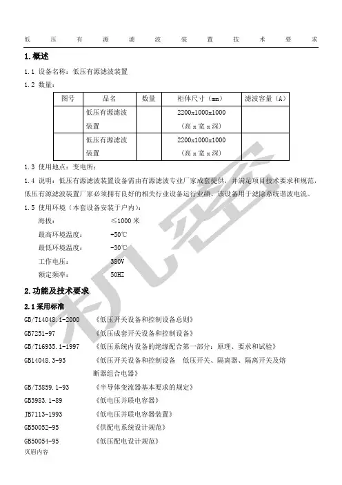
低压有源滤波装置技术要求1.概述1.1 设备名称:低压有源滤波装置1.2 数量:1.31.41.52.2.1GB14048.3-93 《低压开关设备和控制设备低压开关、隔离器、隔离开关及熔断器组合电器》GB/T3859.1-93 《半导体变流器基本要求的规定》GB3983.1-89 《低电压并联电容器》JB7113-1993 《低电压并联电容器装置》GB50052-95 《供配电系统设计规范》GB50054-95 《低压配电设计规范》JGJ/T16-92 《民用建筑电气设计规范》DGJ08-100-2003 《低压用户电气装置规程》IEC 61642 《受谐波影响的工业交流电网、过滤器和并联电容器的应用》IEC 61000-2-4 《电磁兼容(EMC).第2部分:环境—第4分部分:工厂低频传导骚扰兼容水平》IEC 61000-4-7 《电磁兼容(EMC)—第4部分:试验和测量技术—第7分部分:供电系统及所连设备谐波和谐间波和测量和测量仪器导则》GB/T12325-2003 《电能质量供电电压允许偏差》2.22.2.1*2.2.2*2.2.3证书。
*2.2.42.2.51)有源滤波器需要有检测报告认定的滤波效率在95%以上。
2)有源滤波模块要求功率器件采用IGBT,其开关频率为20KHz实现动态补偿,其逆变系统,高可靠性,控制简单,技术达到国际先进水平3)核心控制器件采用国际大品牌器件,如 PWM变流器、电解电容(直流电容)、滤波电容和软磁电抗器、控制器、IGBT、互感器等4)有源滤波器模块要求能快速动态治理谐波,改善电能质量,300us内响应负载变化,全部响应时间小于20ms。
5)MTBF(平均无故障时间)≥10万小时;6)可自动消除系统谐波,并不受系统阻抗影响,本装置功能不受下列因素的影响:6.1)电网阻抗的变化;6.2)要补偿的电流波形形状和电流变化的动态特性;6.3)对称或不对称负荷;在改善电压畸变率,抑制谐波电流主频带,同时保证可靠、安全运行;7)过载能力250%(10ms)。

直流滤波器产品手册直流滤波器是一种电子元件,用于过滤直流电源中的杂波和噪声,以保证电路的正常运行。
直流滤波器产品手册是一份详细介绍直流滤波器产品的手册,其中包含了产品的特点、技术参数、应用场景等信息,为用户提供了全面的了解和选择。
一、产品特点直流滤波器产品具有以下特点:1.高效过滤:直流滤波器能够有效地过滤直流电源中的杂波和噪声,保证电路的稳定性和可靠性。
2.低损耗:直流滤波器采用优质材料和先进工艺,具有低损耗、高效率的特点。
3.稳定性好:直流滤波器具有良好的稳定性和可靠性,能够长时间稳定运行。
4.安装方便:直流滤波器体积小、重量轻,安装方便,适用于各种场合。
二、技术参数直流滤波器产品的技术参数包括:1.额定电压:直流滤波器的额定电压是指其能够承受的最大电压值。
2.额定电流:直流滤波器的额定电流是指其能够承受的最大电流值。
3.工作温度:直流滤波器的工作温度是指其能够正常工作的温度范围。
4.频率范围:直流滤波器的频率范围是指其能够过滤的频率范围。
5.尺寸:直流滤波器的尺寸是指其外形尺寸,包括长度、宽度、高度等。
三、应用场景直流滤波器产品广泛应用于各种电子设备和电路中,包括:1.电源滤波:直流滤波器能够有效地过滤电源中的杂波和噪声,保证电路的正常运行。
2.电机控制:直流滤波器能够对电机控制电路中的噪声进行过滤,提高电机的稳定性和可靠性。
3.通信设备:直流滤波器能够对通信设备中的杂波和噪声进行过滤,提高通信质量和稳定性。
4.医疗设备:直流滤波器能够对医疗设备中的噪声进行过滤,保证医疗设备的正常运行。
总之,直流滤波器产品手册是用户了解和选择直流滤波器产品的重要参考资料,其中包含了产品的特点、技术参数、应用场景等信息,为用户提供了全面的了解和选择。
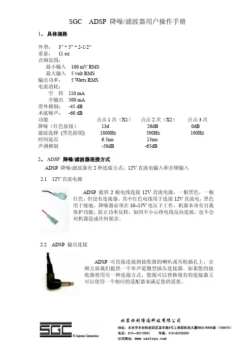
SGC ADSP降噪/滤波器用户操作手册1、具体规格外型:3” * 5” * 2-1/2”重量:11 oz音频范围:最小输入100 mV RMS最大输入 5 volt RMS输出功率: 5 Watts RMS电流消耗:空转110 mA全输出500 mA带外抑制:-45 dB本底噪声:-60 dB功能点击1次(X1)点击2次(X2)点击3次降噪(红色按钮)13d 26dB 0dB滤波选择(黑色按钮) 1800Hz 500Hz 100Hz时间延迟 6.5ms 13ms声调抑制-50dB -65dB2、ADSP降噪/滤波器连接方式ADSP降噪/滤波器有2种连接方式:12V直流电输入和音频输入2.112V直流电源ADSP提供2根电线连接12V直流电源,一根黑色,一根红色,但没有连接器。
其中红色电线用于连接12V直流电,黑色用于接地。
降噪器必须在10~15V电压下工作,机器本身有自我保护功能,防止功率反转,如因不小心将电线反向连接,也不会对机器造成任何损害。
2.2ADSP输出连接ADSP可直接连接到接收器的喇叭或耳机插孔上,音频方面我们提供一个单声道微型插头连接器。
如果您的接收器使用另一种连接方式,您既可以替换现有的连接器又可以使用一个相应的适配器来满足您的需要。
北京保利博通科技有限公司12V电源的连接以及接地,可在任何方便的位置进行3、ADSP降噪/滤波器操作说明ADSP操作非常简便,只需“一键”就能轻松控制降噪和音频抗干扰度。
当电源接通ADSP时,红色LED灯亮。
初始上电后,降噪器会进入旁路模式,音频信号直接连接到降噪器上。
当一级降噪启用时,绿色的LED灯亮。
当二级降噪启用时,两个绿色的LED灯亮。
没有任何LED指示灯亮时,这将视音频情况而定。
2个开关按钮的操作如下图所示:每个开关的功能分别为:•测试ADSP功能:压下&松开ADSP的红色按钮用于X1降噪压下&松开ADSP的红色按钮用于X2降噪压下&松开ADSP的红色按钮停止降噪重复几次验证操作•测试滤波器功能:压下&松开滤波器黑色按钮用于声音过滤压下&松开滤波器黑色按钮用于宽带载波过滤压下&松开滤波器黑色按钮用于窄带载波过滤压下&松开滤波器黑色按钮停止过滤重复几次验证操作4、故障检修当LED灯亮顺序杂乱时,应松开电源,对其进行重新调试。
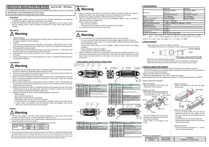
MaintenanceWarningSelection1. Thoroughly and carefully check the purpose of use, required specifications and operatingconditions then select a model with the appropriate specifications.2. Contact SMC beforehand when the product will be used in applications such as a caisson shieldand for breathing and/or medical treatment that affects the human body either directly or indirectly.Mounting1. Operation ManualRead and understand this Operation Manual carefully before mounting and using the productand keep it available for future reference. 2. FlushingFlush and clean the piping before connecting it to the product. If the piping has dust or other contaminants the product may fail or break. Also, ensure that all required mounting parts are firmly fixed before using the product.3. Use tube fittings with resin threads for the piping to the IN and OUT ports. If a fitting with metalthreads is used it may damage the ports. (Only for SFD100)4. Follow directions for the one-touch fitting to connect tubing to the one-touch fitting at the IN andOUT ports.5. Check the flow direction for the tubing indicated by an arrow. Connecting the tubing incorrectlymay damage the element.Installation1. The element may lose its given performance if the pressure difference (pressure drop) betweenthe primary pressure and secondary pressure exceeds 0.1MPa.2. Design your system to allow this product to be mounted in a place without vibrations, which cancause the pressure difference to exceed 0.1MPa.3. Beware of dust from air equipment mounted at the secondary side. If such equipment is mountedthere it may generate dustand decrease the cleanliness of the product. Check the mounting position of the air equipment.4. Set the air-flow capacity with an initial pressure drop of 0.03MPa or less. If the initial pressuredrop exceeds the required value the flow over the rated value will clog the element, which may shorten the product’s life span.5. Determine the appropriate model by assessing the maximum consumption flow rate. When usingcompressed air for an air blow application, calculate the maximum volume of air that will be consumed before selecting the SFD series product size.6. Generally compressed air could contain the following particle contaminants:・Moisture (drain)・Dust sucked from ambient air・Deteriorated oil discharged from compressor・Solid foreign matter such as rust and oil in the piping1) The SFD series is not available for compressed air containing a liquid such as water and oil. 2) Install a dryer, mist separator, micro mist separator, super mist separator, odor removal filter, etc. for the air source used for the SFD series.Piping1. The filter was packed in anti-static closing double packaging in a clean room and the innerpackage should be removed in a clean environment (clean room, etc.).2. For the piping, apply a wrench to two chamfered flats or width-across flats on the IN or OUT side to prevent the product housing from rotating.3. Use the following torque specifications to screw fittings into the product.4. Flush (air blow) the product when the filter is used for the first time or has been replaced. When connecting piping and other fittings flush before first use or when replacing parts to reduce the effect of dust and other contaminants. Also flush the line to eliminate contaminants that may result from installing the pipe line. Be sure to flush the line before actually running the system.1. Follow the procedure described in this manual to replace the element. When the element isreplaced incorrectly it may cause damage and failure to equipment and the machine. 2. Exhaust the air supply completely to release all pressure in the product.3. When the element comes to the end of its life immediately replace it with a new filter orreplacement element (cartridge type). -When to replace the element- ・After one year of operation.・The pressure drop has reached 0.1MPa even before a year elapses.4. Do not disconnect and replace the one-touch fitting.EnvironmentWarningWarning1.Do not use the product in the following environments, which could cause failure.・In or near a place that may be exposed to a corrosive gas, organic solvent or chemicals. ・A place exposed to water, steam or oil. Direct sunlight (ultraviolet) and high temperatures that may deteriorate resin.・A place with a heat source and poor ventilation. (Shade the heat source with heating insulation.)・A place exposed to impact and vibration.・A place exposed to excessive humidity and dust.3. How to mount・Check which side is IN and OUT before connecting.The direction of IN and OUT must follow the arrow marking on the product housing. Arrow marking OUT IN 2.When air blowing, be careful not to contaminate a work piece with entrained ambient air. If air blowing with compressed air the air emitted from a blow nozzle may entrain foreign matter (solid and/or liquid) from the ambient air and attach it to the work piece. Check the ambient environment.1. Description and Function of Each Part・Ensure that each sealing part does not leak.*The figure shows SFD100-C08. ・Keep a space on the cover (at the IN side) to remove the element for maintenance. ・Follow the instructions for the one-touch fitting to connect and disconnect tubing.Warning4. How to replace the elementThe SFD200 element can be replaced. Follow the procedure shown below to replace it.The SFD100 element cannot be disassembled or replaced. It is therefore necessary to replace the entire housing to replace the element. «Reference for the replacement of element»Refer to the following pressure loss value to replace the element.Referential pressure loss for the replacement of element: 0.1MPa (initial pressure loss: 0.03MPa )«How to replace the element»«Element for replacement»Applicable size Part numberIncludingSFD200 SFD-EL200Element + O-ring (3 pcs)Thread size Material torque (N ・m)Resin 2 to 3 Rc1/4Metal 12 to 141)Stop the operation ・Stop the operation of the product and release the internal pressure.2)Remove the cover・Remove the nut and pull out the tie rod. ・Pull out the cover (1) from the elementand remove the rod cover.・Pull out the element from the cover (2). ・Eliminate dust attached to the inside of the case by air blowing.(Ensure there is no damage on the O-ring.)3)Mount the element・Mount a new element on the cover and return the rod cover.4)Mount the rod cover・Line up the flange on the rod cover with the matching socket on the cover, bottom out the rod cover, insert the tie rod, replace the nuts and tighten.Ensure that the cover cannot be pulled out. ・Mount the plain washer to the tie rod which the bracket does not pass.5)Start the operation・Follow the procedure described in “3.How to mount” to start the operation.WarningNut Cover 2 Element Cover socket Plain washer。
Introduction and Applications for Ceramic Band Pass FiltersDATA SHEETFeaturesGHigh Q ceramic G RuggedG Temperature compensated G Custom designsBenefitsGLow insertion loss G Small compact design G Frequency stability G MechanicalstabilityIntroductionTrans-Tech Inc.,a wholly-owned subsidiary of Skyworks Solutions Inc.,is a world-class supplier of high performance ceramic band pass filters.Specializing in band pass,notch and diplexing applications,Trans-Tech can cover a frequency range from 300MHz to 6000MHz with surface mount or connectorized devices.Utilizing state of the art assembly automation,Trans-Tech provides cost-effective solutions meeting high performance specifications.Trans-Tech surface mount PCB configured filters are designed to comply with “green”manufacturing initiatives eliminating heavy metal elements.This configuration is designed to comply with pending European regulations regarding the elimination of lead in electronic assemblies.Custom assemblies can be obtained with flat pack style SMT devices,through-hole or Sn/Pb coated PCB surface mount designs.Trans-Tech assembly methodology offers a wide array of designs,from 2mm x 2pole –8mm x 10pole band pass filters and diplexers,to advanced band stop (notch)designs and high-pass or low-pass filters.For typical applications and ranges of prod-ucts,refer to the Standard Filters/Duplexers listing included in this document.Detailed specifications,both mechanical andelectrical,are maintained for many popular designs on our Web site,or by contacting your local sales representative.The nature of applications utilizing a band pass filter,duplexer or notch filter,necessitates the close interaction of the customer and Trans-Tech application engineering.Our application engi-neers employ the latest in simulation and circuit analysis software with accurately defined design rules to provide rapid turnaround on new filter designs.With our experience and design aids,Trans-Tech can provide the necessary support for your application from prototype through production.In addition to the personal attention,Trans-Tech offers a computer-aideddesign tool,CRaFT,to assist engineers designing filters (the latest version can be downloaded from our Web site,.The strength of Trans-Tech designs begin with our ability to produce our own coaxial resonators from proprietary ceramic formulations.These resonators provide a high Q element that allows us to maintain our low filter insertion loss values.With numerous design package styles,Trans-Tech offers aggressive leadtimes on both prototype and volume applications.DATA SHEET •INTRODUCTION AND APPLICATIONS FOR CERAMIC BAND PASS FILTERSCenter frequency 300MHz to 6GHzStandard filter type Ceramic band pass,duplexer,notch,LPF Number of poles 2–10Resonator sizes 2,3,4,6,8and 12Bandwidth 1.0%–10%(May vary depending on resonator size,F O &εR )Insertion loss 1–4dB typical by design Attenuation Varies by number of poles Impedance 50or 75ΩVSWR2.0:1maximum Operating temperature range -40to +85°CMechanical packaging options PCB surface mount,thru-hole,&flat pack surface mount Power handling (continuous)1W typical*Figure 1.1Standard Capabilities**Contact Skyworks application engineering for assistance with any other requirement.Standard Filters/Duplexers*This list contains Trans-Tech most popular filter and diplexer designs.A variety of footprints and configurations are available for application-specific needs.Please contact the factory or your local representative with your specifications or for more informa-tion on any of these designs.Trans-Tech maintains a list of over 700active filters and diplexers.We welcome every opportunity to assist in the selection or creation of a filter or diplexer that will meet your specifications.Standard Filter Selection GuideTrans-Tech has a wide range of standard filters,as well as the capability to rapidly create new custom designs.Figure 1.1illus-trates our general capability for filters.If a desired requirement falls within the listed categories,Trans-Tech can easily offer a suitable design.Beyond this general list,Trans-Tech has a staff of experienced filter designers who can provide new custom and more technologically difficult filters.In addition,the CRaFT pro-gram functions as a useful tool when analyzing filter requirements.Trans-Tech welcomes the chance to review specifications and determine a design solution.Center FrequencyBandwidth Insertion LossPart Number Filter Type Size/Poles (MHz)(MHz)(dB)Package TT3P2-1068P0-3507Band Pass 3mm/2pole 1068350.7PCB SMT TT4P2-1013P2-2020Band Pass 4mm/2pole 1013202PCB SMT TT4P2-1082.5P2-0720Band Pass 4mm/2pole 1082.572PCB SMT TT4P2-1082P2-0620Band Pass 4mm/2pole 108262PCB SMT TT4P2-1090P2-0610Band Pass 4mm/2pole 109061PCB SMT TT4P3-1030P2-1535Band Pass 4mm/3pole 103015 3.5PCB SMT TT4P3-1067P2-4420Band Pass 4mm/3pole 1067442PCB SMT TT6P4-1080P4-7015Band Pass 6mm/4pole 108070 1.5PCB SMT TT6P4-1090P2-1036Band Pass6mm/4pole1090103.6PCB SMTCATVCenter FrequencyBandwidth Insertion LossPart Number Filter Type Size/Poles (MHz)(MHz)(dB)Package TT6P6-0750P0-5017Band Pass 6mm/4pole 75050 1.7PCB SMT TT6P5-0765P0-11225Band Pass 6mm/5pole 765112 2.5PCB SMT TT6P2-0770T-1215Band Pass 6mm/2pole 77012 1.5PCB SMT TT6P3-0770T-1225Band Pass 6mm/3pole 77012 2.5PCB SMT TT6P3-0770T-2020Band Pass6mm/3pole770202PCB SMTWCSDATA SHEET•INTRODUCTION AND APPLICATIONS FOR CERAMIC BAND PASS FILTERSMDSCenter Frequency Bandwidth Insertion Loss Part Number Filter Type Size/Poles(MHz)(MHz)(dB)PackageTT4P3-2120P2-6020Band Pass4mm/3pole2120602PCB SMTTT4P6-2122P0-2835Band Pass4mm/6pole212228 3.5PCB SMTTT6P4-2158P2-14220Band Pass4mm/4pole2158142PCB SMTTT6P6-2500P3-3635Band Pass6mm/6pole250036 3.5PCB SMTISMCenter Frequency Bandwidth Insertion Loss Part Number Filter Type Size/Poles(MHz)(MHz)(dB)PackageTT4P2-0915P2-2620Band Pass4mm/2pole915262PCB SMTTT6P2-0902F-2518Band Pass6mm/2pole90225 1.8PCB SMTTT6P2-0915T-2518Band Pass6mm/2pole91525 1.8PCB SMTTT6P3-0902T-2520Band Pass6mm/3pole902252PCB SMTTT6P3-0915T-2520Band Pass6mm/3pole915252PCB SMTTT6P3-0917F-1425Band Pass6mm/3pole91714 2.5PCB SMTTT3P3-2400P1-1030Band Pass3mm/3pole2400103PCB SMTTT3P3-2450P1-1445Band Pass3mm/3pole245014 4.5PCB SMTTT6P3-2467P0-3330Band Pass6mm/3pole2467333PCB SMTCellular/PCS/DCS/UMTSCenter Frequency Bandwidth Insertion Loss Part Number Filter Type Size/Poles(MHz)(MHz)(dB)PackageTT3P2-1880P0-6010Band Pass3mm/2pole1880601PCB SMTTT3P3-0881.5P2-2530Band Pass3mm/3pole881.5253PCB SMTTT3P3-1880P0-6022Band Pass3mm/3pole188060 2.2PCB SMTTT3P3-1960P0-6022Band Pass3mm/3pole196060 2.2PCB SMTTT3P3-1960P2-6030Band Pass3mm/3pole1960603PCB SMTTT3P4-0836.5P2-2525Band Pass3mm/4pole836.525 2.5PCB SMTTT3P4-0881.5P2-2525Band Pass3mm/4pole881.525 2.5PCB SMTTT3P4-1880P2-6020Band Pass3mm/4pole1880602PCB SMTTT3P4-1880P2-6030Band Pass3mm/4pole1880603PCB SMTTT4P3-0863P0-0585Band Pass4mm/3pole86358.5PCB SMTTT4P3-2180P1-2540Band Pass4mm/3pole2180254PCB SMTTT4P4-1880P0-6216Band Pass4mm/4pole188062 1.6PCB SMTTT4P4-1960P0-6216Band Pass4mm/4pole196062 1.6PCB SMTTT4P5-2240P2-1032Band Pass4mm/5pole224010 3.2PCB SMTTT4P6-0860.5P0-1937Band Pass4mm/6pole860.519 3.7PCB SMTTT6P3-0836T-2520Band Pass6mm/3pole836252PCB SMTTT6P3-0860P3-2020Band Pass6mm/3pole860202PCB SMTTT6P3-0860T-2020Band Pass6mm/3pole860202PCB SMTTT6P3-0881F-2520Band Pass6mm/3pole881252PCB SMTTT6P5-1960P0-6025Band Pass6mm/5pole196060 2.5PCB SMTTT6P5-2280P1-7032Band Pass6mm/5pole228070 3.2PCB SMTTT6P6-1900P3-8035Band Pass6mm/6pole190080 3.5PCB SMTTT6P3-2140P2-6011Band Pass6mm/3pole214060 1.1PCB SMTTT6P10-R1950-T2140Diplexer6mm/10pole1950--PCB SMTDATA SHEET•INTRODUCTION AND APPLICATIONS FOR CERAMIC BAND PASS FILTERSGPSCenter Frequency Bandwidth Insertion Loss Part Number Filter Type Size/Poles(MHz)(MHz)(dB)Package TT4P4-R1227.6-T1575.42Diplexer6mm/3pole1227.6--PCB SMT TT4P3-1227.6P1-2030Band Pass6mm/3pole1227.6203PCB SMT TT4P3-1575.42P2-2040Band Pass6mm/3pole1575.42204PCB SMT TT3P3-1227.6P1-1030Band Pass6mm/3pole1227.6103PCB SMT TT3P3-1575.42P2-1030Band Pass6mm/3pole1575.42103PCB SMTOtherCenter Frequency Bandwidth Insertion Loss Part Number Filter Type Size/Poles(MHz)(MHz)(dB)Package TT3P4-2513P2-5055Band Pass6mm/3pole251350 5.5PCB SMT TT3P5-3687P1-7466Band Pass6mm/3pole368774 6.6PCB SMT TT4P3-3417P2-0220Band Pass6mm/3pole341722PCB SMT TT4P5-1090P0-1050Band Pass6mm/3pole1090105PCB SMT TT6P5-0810P3-5030Band Pass6mm/3pole810503PCB SMT TT6P4-0509P7-0148Band Pass6mm/3pole5091 4.8PCB SMT TT4P4-1000P2-1030Band Pass6mm/3pole1000103PCB SMT TT6P3-0826.5P3-0520Band Pass6mm/3pole826.552PCB SMT TT6P3-0827P3-0620Band Pass6mm/3pole82562PCB SMT TT6P6-1000P5-8530Band Pass6mm/3pole1000853PCB SMT TT6P6-0545P6-3022Band Pass6mm/3pole54530 2.2PCB SMT TT4P3-3500P2-10020Band Pass6mm/3pole3500102PCB SMT TT6P6-0889P3-4029Band Pass6mm/3pole88940 2.9PCB SMT TT6P4-0722P4-4817Band Pass6mm/3pole72248 1.7PCB SMT TT3P3-1088P2-9015Band Pass6mm/3pole108890 1.5PCB SMT TT6P3-0740P3-2020Band Pass6mm/3pole740202PCB SMT TT6P5-1950P3-6040Band Pass6mm/3pole1950604PCB SMT TT3P4-0917P2-4524Band Pass6mm/3pole91745 2.4PCB SMT TT6P3-1090P2-1029Band Pass6mm/3pole109010 2.9PCB SMT TT6P4-0770P0-1240Band Pass6mm/3pole770124PCB SMT TT6P3-1030P2-1029Band Pass6mm/3pole103010 2.9PCB SMT TT6P5-0881.5P0-2530Band Pass6mm/3pole881.5253PCB SMT TT6P3-0730P3-1213Band Pass6mm/3pole73012 1.3PCB SMT TT6P3-0445.25T-0145Band Pass6mm/3pole445.251 4.5PCB SMT TT4P3-2400P1-20015Band Pass6mm/3pole240020 1.5PCB SMT TT6P3-1080P2-0650Band Pass6mm/3pole108065PCB SMT TT6P3-0745.3P3-1920Band Pass6mm/3pole745.3192PCB SMT TT6P4-0435P0-3019-NS Band Pass6mm/3pole43530 1.9PCB SMT TT3P4-0895.5P2-3926Band Pass6mm/3pole895.539 2.6PCB SMTDATA SHEET •INTRODUCTION AND APPLICATIONS FOR CERAMIC BAND PASS FILTERSAvailable PackagesTrans-Tech offers filters in a number of standard packages.In addition to SMT,Trans-Tech offers a flat-pack and through-hole configuration.Mechanical drawings are provided for most of our filters.In addition to our standard offering,Trans-Tech has the capability and experience to meet many unique footprint layouts and custom packages.For each of our 2to 6pole packages,Trans-Tech can offer pro-files ranging from 2mm to 6mm.2mm SMTTT2P2—P—TT2P3—P—TT2P4—P—TT2P5—P—TT2P6—P—SMT FilterLengthFilter Inches mm P10.43411P20.51213P30.59015P40.66917P50.74819P60.82721P70.90623P0CustomCustomDimension ‘L’will vary in length dependent upon filter’s frequency.DATA SHEET •INTRODUCTION AND APPLICATIONS FOR CERAMIC BAND PASS FILTERSTT3P2—P—3mmSMTTT3P3—P—TT3P4—P—TT3P5—P—TT3P6—P—Dimension ‘L’will vary in length dependent upon filter’s frequency.SMT Filter LengthFilter Inches mm P10.43411P20.51213P30.59015P40.66917P50.74819P60.82721P70.90623P0CustomCustomDATA SHEET •INTRODUCTION AND APPLICATIONS FOR CERAMIC BAND PASS FILTERSTT4P2—P—4mmSMTTT4P3—P—TT4P4—P—TT4P5—P—TT4P6—P—Dimension ‘L’will vary in length dependent upon filter’s frequency.SMT Filter LengthFilter Inches mm P10.43411P20.51213P30.59015P40.66917P50.74819P60.82721P70.90623P0CustomCustomDATA SHEET •INTRODUCTION AND APPLICATIONS FOR CERAMIC BAND PASS FILTERSTT6P2—P—6mmSMTTT6P3—P—TT6P4—P—TT6P5—P—TT6P6—P—Dimension ‘L’will vary in length dependent upon filter’s frequency.SMT Filter LengthFilter Inches mm P10.43411P20.51213P30.59015P40.66917P50.74819P60.82721P70.90623P0CustomCustomDATA SHEET •INTRODUCTION AND APPLICATIONS FOR CERAMIC BAND PASS FILTERS6mm Flat Pack (F)6mm Thru-Hole (T)TT6P2—FTT6P2—TTT6P3—TTT6P3—FDimension ‘L’will vary in length dependent upon filter’s frequency.DATA SHEET•INTRODUCTION AND APPLICATIONS FOR CERAMIC BAND PASS FILTERSCopyright©2006,2007,Trans-Tech Inc.,Inc.All Rights Reserved.Information in this document is provided in connection with Trans-Tech,Inc.("Trans-Tech"),a wholly-owned subsidiary of Skyworks Solutions,Inc.These materials,including the information contained herein,are provided by Trans-Tech as a service to its customers and may be used for informational purposes only by the customer.Trans-Tech assumes no responsibility for errorsor omissions in these materials or the information contained herein.Trans-Tech may change its documentation,products,services,specifications or product descriptions at any time,without notice.Trans-Tech makes no commitment to update the materials or information and shall have no responsibility whatsoever for conflicts,incompatibilities,or other difficulties arising fromany future changes.No license,whether express,implied,by estoppel or otherwise,is granted to any intellectual property rights by this document.Trans-Tech assumes no liability for any materials,products or information provided hereunder,including the sale,distribution,reproduction or use of Trans-Tech products,information or materials,except as may be provided in Trans-Tech Terms and Conditions of Sale.THE MATERIALS,PRODUCTS AND INFORMATION ARE PROVIDED"AS IS"WITHOUT WARRANTY OF ANY KIND,WHETHER EXPRESS,IMPLIED,STATUTORY,OR OTHERWISE,INCLUDING FITNESS FOR A PARTICULAR PURPOSE OR USE,MERCHANTABILITY,PERFORMANCE,QUALITY OR NON-INFRINGEMENT OF ANY INTELLECTUAL PROPERTY RIGHT;ALL SUCH WARRANTIES ARE HEREBY EXPRESSLY DISCLAIMED.TRANS-TECH DOES NOT WARRANT THE ACCURACY OR COMPLETENESS OF THE INFORMATION,TEXT,GRAPHICS OR OTHER ITEMS CONTAINED WITHIN THESE MATERIALS.TRANS-TECH SHALL NOT BE LIABLE FOR ANY DAMAGES,INCLUDING BUT NOT LIMITED TO ANY SPECIAL,INDIRECT,INCIDENTAL,STATUTORY,OR CONSEQUENTIAL DAMAGES,INCLUDING WITHOUT LIMITATION, LOST REVENUES OR LOST PROFITS THAT MAY RESULT FROM THE USE OF THE MATERIALS OR INFORMATION,WHETHER OR NOT THE RECIPIENT OF MATERIALS HAS BEEN ADVISED OF THE POSSIBILITY OF SUCH DAMAGE.Trans-Tech products are not intended for use in medical,lifesaving or life-sustaining applications,or other equipment in which the failure of the Trans-Tech products could lead to personal injury, death,physical or environmental damage.Trans-Tech customers using or selling Trans-Tech products for use in such applications do so at their own risk and agree to fully indemnify Trans-Tech for any damages resulting from such improper use or sale.Customers are responsible for their products and applications using Trans-Tech products,which may deviate from published specifications as a result of design defects,errors,or operation of products outside of published parameters or design specifications.Customers should include design and operating safeguards to minimize these and other risks.Trans-Tech assumes no liability for applications assistance,customer product design,or damage to any equipment resulting from the use of Trans-Tech products outside of stated published specifications or parameters.。

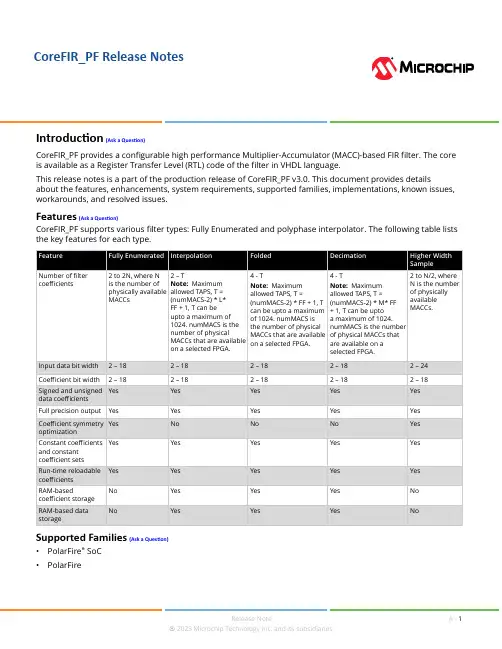
CoreFIR_PF Release NotesCoreFIR_PF provides a configurable high performance Multiplier-Accumulator (MACC)-based FIR filter. The core is available as a Register Transfer Level (RTL) code of the filter in VHDL language.This release notes is a part of the production release of CoreFIR_PF v3.0. This document provides details about the features, enhancements, system requirements, supported families, implementations, known issues, workarounds, and resolved issues.Features (Ask a Question)CoreFIR_PF supports various filter types: Fully Enumerated and polyphase interpolator. The following table liststhe key features for each type.Supported Families (Ask a Question)•PolarFire® SoC•PolarFireTable of ContentsIntroduction (1)Features (1)Supported Families (1)1. Overview (3)1.1. Licensing (3)1.2. Supported Tool Flows (3)1.3. Installation Instructions (3)1.4. Supported Test Environments (3)2. Discontinued Features and Devices (4)3. Known Limitations and Workarounds (5)4. Resolved Issues (6)4.1. Resolved Issues in the CoreFIR_PF v3.0 Release (6)4.2. Resolved Issues in the CoreFIR_PF v2.3 Release (6)4.3. Resolved Issues in the CoreFIR_PF v2.2 Release (6)4.4. Resolved Issues in the CoreFIR_PF v2.1 Release (6)4.5. Resolved Issues in the CoreFIR_PF v2.0 Release (6)5. Revision History (7)Microchip FPGA Support (8)Microchip Information (8)The Microchip Website (8)Product Change Notification Service (8)Customer Support (8)Microchip Devices Code Protection Feature (8)Legal Notice (9)Trademarks (9)Quality Management System (10)Worldwide Sales and Service (11)Overview 1. Overview (Ask a Question)This release contains a copy of the CoreFIR_PF user guide. The user guide, describes the IP corefunctionalities and provides step-by-step instructions on how to simulate, synthesize, and place-and-route this IP core, and also provides implementation suggestions.For updates and additional information about the software, devices, and hardware, visit theIntellectual Property pages on the Microchip FPGA Products Group website.1.1 Licensing (Ask a Question)CoreFIR_PF is freely distributed with Microchip Libero SoC. Complete HDL source code is providedfor the core and testbenches.1.2 Supported Tool Flows (Ask a Question)CoreFIR_PF v3.0 requires Libero System-on-Chip (SoC) software v12.0 or later.1.3 Installation Instructions (Ask a Question)The IP core must be installed to the IP Catalog of Libero SoC software. This is done automaticallythrough the IP Catalog update function in Libero SoC software, or the IP core can be manuallydownloaded from the catalog. Once the IP core is installed in Libero SoC software IP Catalog, thecore can be configured, generated, and instantiated within SmartDesign for inclusion in the Liberoproject.1.4 Supported Test Environments (Ask a Question)The test environment supported for default configuration constant coefficient set, VHDL usertestbench.Discontinued Features and Devices 2. Discontinued Features and Devices (Ask a Question)CoreFIR_PF discontinued support for SmartFusion2 and IGLOO2 devices. These devices aresupported in CoreFIR v8.6.Known Limitations and Workarounds 3. Known Limitations and Workarounds (Ask a Question)None.4. Resolved Issues (Ask a Question)This topic describes the resolved issues for the various CoreFIR_PF core releases.4.1 Resolved Issues in the CoreFIR_PF v3.0 Release (Ask a Question)The following table lists all the resolved issues in the CoreFIR_PF v3.0 release.4.2 Resolved Issues in the CoreFIR_PF v2.3 Release (Ask a Question)There were no issues reported or resolved in the CoreFIR_PF v2.3 release. PolarFire SoC support was added.4.3 Resolved Issues in the CoreFIR_PF v2.2 Release (Ask a Question)The following table lists all the resolved issues in the CoreFIR_PF v2.2 release.4.4 Resolved Issues in the CoreFIR_PF v2.1 Release (Ask a Question)The following table lists all the resolved issues in the CoreFIR_PF v2.1 release.4.5 Resolved Issues in the CoreFIR_PF v2.0 Release (Ask a Question)The following table lists all the resolved issues in the CoreFIR_PF v2.0 release.5. Revision History (Ask a Question)The revision history describes the changes that were implemented in the document. The changes are listed by revision, starting with the most current publication.Microchip FPGA products group backs its products with various support services, including Customer Service, Customer Technical Support Center, a website, and worldwide sales offices. Customers are suggested to visit Microchip online resources prior to contacting support as it is very likely that their queries have been already answered.Contact Technical Support Center through the website at /support. Mention the FPGA Device Part number, select appropriate case category, and upload design files while creating a technical support case.Contact Customer Service for non-technical product support, such as product pricing, product upgrades, update information, order status, and authorization.•From North America, call 800.262.1060•From the rest of the world, call 650.318.4460•Fax, from anywhere in the world, 650.318.8044The Microchip Website (Ask a Question)Microchip provides online support via our website at /. This website is used to make files and information easily available to customers. Some of the content available includes:•Product Support – Data sheets and errata, application notes and sample programs, design resources, user’s guides and hardware support documents, latest software releases and archived software•General Technical Support – Frequently Asked Questions (FAQs), technical support requests, online discussion groups, Microchip design partner program member listing•Business of Microchip – Product selector and ordering guides, latest Microchip press releases, listing of seminars and events, listings of Microchip sales offices, distributors and factoryrepresentativesProduct Change Notification Service (Ask a Question)Microchip’s product change notification service helps keep customers current on Microchip products. Subscribers will receive email notification whenever there are changes, updates, revisions or errata related to a specified product family or development tool of interest.To register, go to /pcn and follow the registration instructions.Customer Support (Ask a Question)Users of Microchip products can receive assistance through several channels:•Distributor or Representative•Local Sales Office•Embedded Solutions Engineer (ESE)•Technical SupportCustomers should contact their distributor, representative or ESE for support. Local sales offices are also available to help customers. A listing of sales offices and locations is included in this document. Technical support is available through the website at: /support Microchip Devices Code Protection Feature (Ask a Question)Note the following details of the code protection feature on Microchip products:•Microchip products meet the specifications contained in their particular Microchip Data Sheet.•Microchip believes that its family of products is secure when used in the intended manner, within operating specifications, and under normal conditions.•Microchip values and aggressively protects its intellectual property rights. Attempts to breach the code protection features of Microchip product is strictly prohibited and may violate the Digital Millennium Copyright Act.•Neither Microchip nor any other semiconductor manufacturer can guarantee the security of its code. Code protection does not mean that we are guaranteeing the product is “unbreakable”.Code protection is constantly evolving. Microchip is committed to continuously improving the code protection features of our products.Legal Notice (Ask a Question)This publication and the information herein may be used only with Microchip products, includingto design, test, and integrate Microchip products with your application. Use of this informationin any other manner violates these terms. Information regarding device applications is provided only for your convenience and may be superseded by updates. It is your responsibility to ensure that your application meets with your specifications. Contact your local Microchip sales office for additional support or, obtain additional support at /en-us/support/design-help/ client-support-services.THIS INFORMATION IS PROVIDED BY MICROCHIP "AS IS". MICROCHIP MAKES NO REPRESENTATIONS OR WARRANTIES OF ANY KIND WHETHER EXPRESS OR IMPLIED, WRITTEN OR ORAL, STATUTORY OR OTHERWISE, RELATED TO THE INFORMATION INCLUDING BUT NOT LIMITED TO ANY IMPLIED WARRANTIES OF NON-INFRINGEMENT, MERCHANTABILITY, AND FITNESS FOR A PARTICULAR PURPOSE, OR WARRANTIES RELATED TO ITS CONDITION, QUALITY, OR PERFORMANCE.IN NO EVENT WILL MICROCHIP BE LIABLE FOR ANY INDIRECT, SPECIAL, PUNITIVE, INCIDENTAL, OR CONSEQUENTIAL LOSS, DAMAGE, COST, OR EXPENSE OF ANY KIND WHATSOEVER RELATED TO THE INFORMATION OR ITS USE, HOWEVER CAUSED, EVEN IF MICROCHIP HAS BEEN ADVISED OF THE POSSIBILITY OR THE DAMAGES ARE FORESEEABLE. TO THE FULLEST EXTENT ALLOWED BY LAW, MICROCHIP'S TOTAL LIABILITY ON ALL CLAIMS IN ANY WAY RELATED TO THE INFORMATION ORITS USE WILL NOT EXCEED THE AMOUNT OF FEES, IF ANY, THAT YOU HAVE PAID DIRECTLY TO MICROCHIP FOR THE INFORMATION.Use of Microchip devices in life support and/or safety applications is entirely at the buyer's risk, and the buyer agrees to defend, indemnify and hold harmless Microchip from any and all damages, claims, suits, or expenses resulting from such use. No licenses are conveyed, implicitly or otherwise, under any Microchip intellectual property rights unless otherwise stated.Trademarks (Ask a Question)The Microchip name and logo, the Microchip logo, Adaptec, AVR, AVR logo, AVR Freaks, BesTime, BitCloud, CryptoMemory, CryptoRF, dsPIC, flexPWR, HELDO, IGLOO, JukeBlox, KeeLoq, Kleer, LANCheck, LinkMD, maXStylus, maXTouch, MediaLB, megaAVR, Microsemi, Microsemi logo, MOST, MOST logo, MPLAB, OptoLyzer, PIC, picoPower, PICSTART, PIC32 logo, PolarFire, Prochip Designer, QTouch, SAM-BA, SenGenuity, SpyNIC, SST, SST Logo, SuperFlash, Symmetricom, SyncServer, Tachyon, TimeSource, tinyAVR, UNI/O, Vectron, and XMEGA are registered trademarks of Microchip Technology Incorporated in the U.S.A. and other countries.AgileSwitch, APT, ClockWorks, The Embedded Control Solutions Company, EtherSynch, Flashtec, Hyper Speed Control, HyperLight Load, Libero, motorBench, mTouch, Powermite 3, Precision Edge, ProASIC, ProASIC Plus, ProASIC Plus logo, Quiet- Wire, SmartFusion, SyncWorld, Temux, TimeCesium, TimeHub, TimePictra, TimeProvider, TrueTime, and ZL are registered trademarks of Microchip Technology Incorporated in the U.S.A.Adjacent Key Suppression, AKS, Analog-for-the-Digital Age, Any Capacitor, AnyIn, AnyOut, Augmented Switching, BlueSky, BodyCom, Clockstudio, CodeGuard, CryptoAuthentication, CryptoAutomotive, CryptoCompanion, CryptoController, dsPICDEM, , DynamicAverage Matching, DAM, ECAN, Espresso T1S, EtherGREEN, GridTime, IdealBridge, In-Circuit Serial Programming, ICSP, INICnet, Intelligent Paralleling, IntelliMOS, Inter-Chip Connectivity, JitterBlocker, Knob-on-Display, KoD, maxCrypto, maxView, memBrain, Mindi, MiWi, MPASM, MPF, MPLAB Certified logo, MPLIB, MPLINK, MultiTRAK, NetDetach, Omniscient Code Generation, PICDEM, , PICkit, PICtail, PowerSmart, PureSilicon, QMatrix, REAL ICE, Ripple Blocker, RTAX, RTG4, SAM-ICE, Serial Quad I/O, simpleMAP, SimpliPHY, SmartBuffer, SmartHLS, SMART-I.S., storClad, SQI, SuperSwitcher, SuperSwitcher II, Switchtec, SynchroPHY, Total Endurance, Trusted Time, TSHARC, USBCheck, VariSense, VectorBlox, VeriPHY, ViewSpan, WiperLock, XpressConnect, and ZENA are trademarks of Microchip Technology Incorporated in the U.S.A. and other countries.SQTP is a service mark of Microchip Technology Incorporated in the U.S.A.The Adaptec logo, Frequency on Demand, Silicon Storage Technology, and Symmcom are registered trademarks of Microchip Technology Inc. in other countries.GestIC is a registered trademark of Microchip Technology Germany II GmbH & Co. KG, a subsidiary of Microchip Technology Inc., in other countries.All other trademarks mentioned herein are property of their respective companies.© 2023, Microchip Technology Incorporated and its subsidiaries. All Rights Reserved.ISBN:Quality Management System (Ask a Question)For information regarding Microchip’s Quality Management Systems, please visit/quality.Worldwide Sales and ServiceRelease Note© 2023 Microchip Technology Inc. and its subsidiaries A - 11。
EMI2121, SZEMI2121Single Pair Common Mode Filter with ESD Protection DescriptionThe EMI2121 is an integrated common mode filter providing both ESD protection and EMI filtering for high speed serial digital interfaces such as USB2.0.The EMI2121 provides EMI filtering for one differential data line pair and ESD protection for one data pair plus a supply input such as USB2.0 Vbus or USB ID pin. It is supplied in a small RoHS−compliant WDFN8 package.Features•Highly Integrated Common Mode Filter (CMF) with ESD Protection provides protection and EMI Reduction for systems using high speed Serial Data Lines with cost and space savings over Discrete Solutions •Large Differential Mode Bandwidth with Cutoff Frequency > 2 GHz •High Common Mode Stop Band Attenuation: >25 dB at 700 MHz, >30 dB at 800 MHz Typical•Provides ESD Protection to IEC61000−4−2 Level 4, ±12 kV Contact Discharge•Low Channel Input Capacitance provides Superior Impedance Matching Performance•Low Profile Package with Small Footprint in WDFN8 2.0 mm length x 2.2 mm width x 0.75 mm height Pb−Free Package•SZ Prefix for Automotive and Other Applications Requiring Unique Site and Control Change Requirements; AEC−Q101 Qualified and PPAP Capable•These Devices are Pb−Free, Halogen Free/BFR Free and are RoHS CompliantApplications•USB2.0 and other High Speed Differential Data Lines in Mobile Phones, Digital Still Cameras, and Automotive interfaces •MIPI D−PHYDevice Package Shipping†ORDERING INFORMATIONEMI2121MTTAG WDFN8(Pb−Free)3000/T ape & ReelWDFN8CASE 511BNMARKINGDIAGRAMSIMPLIFIED SCHEMATIC†For information on tape and reel specifications, including part orientation and tape sizes, please refer to our Tape and Reel Packaging Specification Brochure, BRD8011/D.(Note: Microdot may be in either location)PIN CONNECTIONSC2= Specific Device CodeM= Date CodeG= Pb−Free Device1Out_1+Out_1−In_1+In_1−V DD/I D GNDGNDGND(Top View)Internal(ASIC) External(Connector)SZEMI2121MTTAG WDFN8(Pb−Free)3000/T ape & ReelPIN DESCRIPTIONPin No.Pin Name Type Description1In_1+I/O CMF Channel 1+ to Connector (External)2In_1−I/O CMF Channel 1− to Connector (External)8Out_1+I/O CMF Channel 1+ to ASIC (Internal)7Out_1−I/O CMF Channel 1− to ASIC (Internal)6V DD/I D I/O Supply Protection to Connector (External)3,4,5GND GND GroundMAXIMUM RATINGS (T A = 25°C unless otherwise stated)Parameter Symbol Value Units Operating Temperature Range T OP−40 to +85°C Storage Temperature Range T STG−65 to +150°C Maximum Lead Temperature for Soldering Purposes (1/8” from Case for 10 Seconds)T L260°C DC Current per Line I LINE100mA Stresses exceeding those listed in the Maximum Ratings table may damage the device. If any of these limits are exceeded, device functionality should not be assumed, damage may occur and reliability may be affected.ELECTRICAL CHARACTERISTICS (T A = 25°C unless otherwise specified)Parameter Symbol Test Conditions Min Typ Max Unit Channel Leakage Current I LEAK T A = 25°C, V IN = 5 V, GND = 0 V 1.0m A Channel Negative Voltage V F T A = 25°C, I F= 10 mA0.1 1.5VChannel Input Capacitance to ground (Pins 1,2,4,5 to Pins 3,8)C IN T A = 25°C, At 1 MHz, GND = 0 V,V IN = 1.65 V0.8 1.3pFChannel Resistance (Pins 1−16, 2−15, 4−13,5−12, 7−10 and 9−9)Rch8.0W Differential Mode Cut*Off Frequency f3dB50 W source and load termination 2.0GHz Common Mode Stop Band Attenuation F atten@ 800 MHz30dBIn−system ESD Withstand Voltagea) Contact discharge per IEC 61000−4−2 standard, Level 4 (External Pins)b) Contact discharge per IEC 61000−4−2 standard, Level 1 (Internal Pins)V ESD(Notes 1 and 2)±12±2kVTLP Clamping Voltage (See Figure 9)V CL Forward I PP = 8 AForward I PP = 12 AReverse I PP = −8 AReverse I PP = −12 A1316−6−8.5VVVVReverse Working Voltage V RWM(Note 3) 5.0V Breakdown Voltage V BR I T = 1 mA; (Note 4) 5.59.0V Maximum Peak Pulse Current (Pin 6 to GND)I PP8x20 m s Waveform12A Clamping Voltage (Pin 6 to GND)V C I PP = 5 A10VDynamic Resistance Positive Transients Negative Transients R DYN T A= 25C, I PP=1 A, t P= 8/20 us,Any I/O to GND0.670.59WW1.Standard IEC 61000−4−2 with C Discharge = 150 pF, R Discharge = 330, GND grounded.2.These measurements performed with no external capacitor.S devices are normally selected according to the working peak reverse voltage (V RWM), which should be equal or greater than the DCor continuous peak operating voltage level.4.V BR is measured at pulse test current I T.Normal (Differential) ModeFigure 1. Normal (Differential) Mode TestConfigurationFigure 2. Application CircuitTYPICAL CHARACTERISTICSFigure 3. Differential Mode Attenuation vs.Frequency (Zdiff = 100 W)Figure 4. Common Mode Attenuation vs.Frequency (Zcomm = 50 W)Figure 5. Differential Return Loss vs. Frequency(Zdiff=100 W)Figure 6. Differential Impedance vs. Frequency(Zdiff=100 W)Figure 7. EMI2121 Measured Eye Diagram @ 480 MbpsTransmission Line Pulse (TLP) MeasurementsTransmission Line Pulse (TLP) provides current versus voltage (I −V) curves in which each data point is obtained from a 100 ns long rectangular pulse from a charged transmission line. A simplified schematic of a typical TLP system is shown in Figure 8. TLP I −V curves of ESD protection devices accurately demonstrate the product’s ESD capability because the 10 s of amps current levels and under 100 ns time scale match those of an ESD event. This is illustrated in Figure 9 where an 8 kV IEC61000−4−2 current waveform is compared with TLP current pulses at 8 and 16 A. A TLP curve shows the voltage at which the device turns on as well as how well the device clamps voltage over a range of current levels. Typical TLP I −V curves for the EMI2121 are shown in Figure 10.Figure 8. Simplified Schematic of a Typical TLP SystemFigure 9. Comparison Between 8 kV IEC61000−4−2 and 8 A and 16 A TLP WaveformsFigure 10. Positive and Negative TLP WaveformsESD Voltage ClampingFor sensitive circuit elements it is important to limit the voltage that an IC will be exposed to during an ESD event to as low a voltage as possible. The ESD clamping voltage is the voltage drop across the ESD protection diode during an ESD event per the IEC61000−4−2 waveform. Since the IEC61000−4−2 was written as a pass/fail spec for larger systems such as cell phones or laptop computers it is not clearly defined in the spec how to specify a clamping voltage at the device level. ON Semiconductor has developed a way to examine the entire voltage waveform across the ESD protection diode over the time domain of an ESD pulse in the form of an oscilloscope screenshot, which can be found on the datasheets for all ESD protection diodes. For more information on how ON Semiconductor creates these screenshots and how to interpret them please refer to On Semiconductor Application Notes AND8307/D and AND8308/D.IEC61000−4−2 Spec.Level Test Volt-age (kV)First Peak Current (A)Current at 30 ns (A)Current at 60 ns (A)127.5422415843622.51264830168IEC61000−4−2 WaveformFigure 12. 8 x 20 ms Pulse Waveform1009080706050403020100t, TIME (m s)% O F P E A K P U L S E C U R R E N TFigure 13. ESD Clamping Voltage +8 kV per IEC6100−4−2 (external to internal pin)Figure 14. ESD Clamping Voltage −8 kV per IEC6100−4−2 (external to internal pin)Micro USBConnector(Top View)Figure 15. EMI2121 Micro − USB Connector Application DiagramWDFN8, 2.2x2, 0.5PCASE 511BN ISSUE ADATE 11 DEC 2012NOTES:1.DIMENSIONING AND TOLERANCING PER ASME Y14.5M, 1994.2.CONTROLLING DIMENSION: MILLIMETERS.3.DIMENSION b APPLIES TO PLATED TERMINAL AND IS MEASURED BETWEEN 0.15 AND 0.25 mm FROM TERMINAL.4.COPLANARITY APPLIES TO THE EXPOSED PAD AS WELL AS THE TERMINALS.BOTTOM VIEW2XSEATING PLANEDIM MIN MAX MILLIMETERS A 0.700.80A10.000.05b 0.150.25D 2.20 BSC D20.340.54E 2.00 BSC E20.600.80e 0.50 BSC L10.050.15L20.300.50L30.150.25DIMENSIONS: MILLIMETERS*For additional information on our Pb −Free strategy and soldering details, please download the ON Semiconductor Soldering and Mounting Techniques Reference Manual, SOLDERRM/D.RECOMMENDEDGENERICMARKING DIAGRAM*XX = Specific Device Code M = Date Code G = Pb −Free Device*This information is generic. Please referto device data sheet for actual part marking.Pb −Free indicator, “G” or microdot “ G ”,may or may not be present.L1DETAIL AOPTIONAL CONSTRUCTIONSDETAIL BOPTIONAL CONSTRUCTIONSA30.20 REF b10.250.35L 0.750.95DETAIL Cb1SOLDERING FOOTPRINT*MECHANICAL CASE OUTLINEPACKAGE DIMENSIONSON Semiconductor and are trademarks of Semiconductor Components Industries, LLC dba ON Semiconductor or its subsidiaries in the United States and/or other countries.ON Semiconductor reserves the right to make changes without further notice to any products herein. ON Semiconductor makes no warranty, representation or guarantee regarding the suitability of its products for any particular purpose, nor does ON Semiconductor assume any liability arising out of the application or use of any product or circuit, and specifically disclaims any and all liability, including without limitation special, consequential or incidental damages. ON Semiconductor does not convey any license under its patent rights nor thePUBLICATION ORDERING INFORMATIONTECHNICAL SUPPORTNorth American Technical Support:Voice Mail: 1 800−282−9855 Toll Free USA/Canada Phone: 011 421 33 790 2910LITERATURE FULFILLMENT :Email Requests to:*******************onsemi Website: Europe, Middle East and Africa Technical Support:Phone: 00421 33 790 2910For additional information, please contact your local Sales Representative。
S VF 1U M ultimode State Variable FilterM anual (English)R evision: 2023.07.24T ABLE OF CONTENTSC OMPLIANCE 3 I NSTALLATION 4B efore You Start 4I nstalling Your Module 5 F RONT PANEL 6C ontrols 6J acks 7 B ACK PANEL 8 T ECHNICAL SPECIFICATIONS 8C OMPLIANCET his device complies with Part 15 of the FCC Rules. Operation is subject tot he following two conditions: (1) this device may not cause harmfuli nterference, and (2) this device must accept any interference received,i ncluding interference that may cause undesired operation.C hanges or modifications not expressly approved by Intellijel Designs, Inc.c ould void the user’s authority to operate the equipment.A ny digital equipment has been tested and found to comply with the limits for aC lass A digital device, pursuant to part 15 of the FCC Rules. These limits ared esigned to provide reasonable protection against harmful interference whent he equipment is operated in a commercial environment. This equipmentg enerates, uses, and can radiate radio frequency energy and, if not installeda nd used in accordance with the instruction manual, may cause harmfuli nterference to radio communications.T his device meets the requirements of the following standards and directives:E MC: 2014/30/EUE N55032:2015 ; EN55103-2:2009 (EN55024) ; EN61000-3-2 ; EN61000-3-3L ow Voltage: 2014/35/EUE N 60065:2002+A1:2006+A11:2008+A2:2010+A12:2011R oHS2: 2011/65/EUW EEE: 2012/19/EUI NSTALLATIONT his module is designed for use within anI ntellijel-standard 1U row, such as containedw ithin the Intellijel Palette, or 4U and 7UE urorack cases. Intellijel’s 1U specification isd erived from the Eurorack mechanicals pecification set by Doepfer that is designed tos upport the use of lipped rails within industrys tandard rack heights.B efore You StartB efore installing a new module in your case, you must ensure your power supply has a free powerh eader and sufficient available capacity to power the module:●S um up the specified +12V current draw for all modules, including the new one. Do the same fort he -12 V and +5V current draw. The current draw will be specified in the manufacturer'st echnical specifications for each module.●C ompare each of the sums to specifications for your case’s power supply.●O nly proceed with installation if none of the values exceeds the power supply’s specifications.O therwise you must remove modules to free up capacity or upgrade your power supply.Y ou will also need to ensure your case has enough free space (hp) to fit the new module. Top revent screws or other debris from falling into the case and shorting any electrical contacts, do not l eave gaps between adjacent modules, and cover all unused areas with blank panels. Similarly, do n ot use open frames or any other enclosure that exposes the backside of any module or the powerd istribution board.Y ou can use a tool like M odularGrid t o assist in your p lanning. Failure to adequately power your m odules may result in damage to your modules or power supply. If you are unsure, please c ontact u s b efore proceeding.I nstalling Your ModuleW hen installing or removing a module, always turn offt he power to the case and disconnect the power cable.F ailure to do so may result in serious injury or equipmentd amage.E nsure the 10-pin connector on the power cable isc onnected correctly to the module before proceeding.T he red stripe on the cable must line up with the -12Vp ins on the module’s power connector. The pins arei ndicated with the label -12V, a white stripe next to thec onnector, the words “red stripe”, or some combination oft hose indicators. Some modules have shrouded headerst o prevent accidental reversal.M ost modules will come with the cable alreadyc onnected, but it is good to double check the orientation.B e aware that some modules may have headers thats erve other purposes so ensure the cable is connectedt o the correct one.T he other end of the cable, with a 16-pin connector,c onnects to the power bus board of your Eurorack case.E nsure the red stripe on the cable lines up with the -12Vp ins on the bus board. On Intellijel power supplies thep ins are labeled with “-12V” and/or a thick white stripe,w hile others have shrouded headers to preventa ccidental reversal:I f you’re using another manufacturer’s power supply,c heck their documentation for instructions.B efore reconnecting power and turning on your modulars ystem, double check that the ribbon cable is fully seatedo n both ends and that all the pins are correctly aligned. Ift he pins are misaligned in any direction or the ribbon isb ackwards you can cause damage to your module,p ower supply, or other modules.A fter you have confirmed all the connections, you canr econnect the power cable and turn on your modular system. You should immediately check that all y our modules have powered on and are functioning correctly. If you notice any anomalies, turn your s ystem off right away and check your cabling again for mistakes.F RONT PANELC ontrols[1] C UTOFF - Sets the cutofff requency of the filter.T he filter’s actualf requency is ac ombination of this settingp lus any modulationa pplied to either theP ITCH CV [B] o rF M CV [C] i nputs.[2] Q- Sets the resonance of the filter. When fully clockwise, t he filter will self-oscillate.[3] F M - Attenuverts the voltage patched into the F M CV [C] i nput.W ith the knob turned clockwise from noon, the filter’s C UTOFF [1] f requency increases as theF M CV [C] v oltage increases. With the knob turned c ounterclockwise from noon, the filter’sC UTOFF [1] f requency decreases as the F M CV [C] v oltage i ncreases. With the knob straightu p (‘noon’ position), none of the F M CV [C] i nput m odulates the C UTOFF [1] f requency.[4] C LIP s witch - Selects whether the filter input is s oft clipped or not and, if so, whether or not anyg ain is added to the input signal. Specifically:+6dB : In the UP position, the input is soft clipped t o a nominal level, and then boosted by6dB, providing a hot signal to the filter. This is particularly useful for boosting low level inputs ignals and/or giving them extra harmonic character for filtering.x: In the MIDDLE position, the input signal is passed s traight through to the filter without anys oft clipping or input gain.S OFT CLIP :I n the DOWN position, the input is soft c lipped to a nominal level, but noa dditional signal boost is added. This setting is good for taming hot signal sources. Thee ffect can be fairly subtle u nless the input is hotter t han normal (i.e. it contains a mix ofs ignals), or is lacking in harmonics, such as a sine or triangle wave.T he corresponding LED indicates t he post CLIP switch s ignal level (i.e., the signal level goingi nto the filter circuit). The brighter the LED, the hotter the signal.[5] B P/NOTCH s witch - Selects whether the B P/N [D] j ack o utputs a bandpass ( B P ) filter or aN OTCH f ilter.N OTE: The L P/HP trimmer o n the back panel adjusts t he LP/HP balance of the notch —a ltering the volume, sonic character and resonance produced by a notch filter. SeeB ACK PANEL f or more information.J acks[A] I N - Input to the SVF 1Um odule.[B] P ITCH CV I n - CV inputf or controlling the cutofff requency. This jacka ccepts 1 V/oct signals,a nd allows theC UTOFF [1] f requency tot rack a keyboard ors equencer input. This is particularly useful when Q[2] i s set to maximum (causing the filter to s elf-oscillate), since it enables the filter to be used as a sine wave oscillator, accurately tracking t he pitch of the incoming CV.[C] F M CV I n - CV input for controlling the cutoff frequency. T he voltage arriving at this jack isa ttenuverted by the F M [3] k nob, making it ideal for e nvelopes, LFOs and other modulations ources.[D] B P/N O ut - Switchable 2-pole (12 dB/Oct) bandpass o r notch filter output. The choice betweenB P a nd N otch i s made using the B P/NOTCH [5] s witch.[E] L P O ut - Dedicated 2-pole (12 dB / oct) low pass filter o utput.[F] H P O ut - Dedicated 2-pole (12 dB / oct) high pass f ilter output.B ACK PANELT here are two trim pots on the back panel:[1] P ITCH - This trimmer I S NOT i ntended for customer u se. It calibrates the filter’s Volt/Octt racking. Tracking is calibrated at the factory, so it should not be touched unless something has k nocked it out of calibration, and you’re comfortable adjusting it.[2] L P/HP - This trimmer I S i ntended for customer use. I t adjusts the balance of the notch filter —t hat is, whether it’s perfectly symmetrical (resulting in no resonance) or skewed toward the LP orH P side. In the middle (50%), the notch is perfectly symmetrical, but results in no resonancea nd a decreased output level. Turning the trimmer to either side will accentuate either thel owpass or highpass side of the notch, resulting in more volume and resonance. The trimmer isf actory set to around 75% HP / 25% LP, providing a nice balance of symmetry, volume, andr esonance — but if you’d like the notch to have a different sonic characteristic, you can find it via t his trimmer.T ECHNICAL SPECIFICATIONSW idth 20 hpM aximum Depth 35 mmC urrent Draw 27 mA @ +12V30 mA @ -12V。
产品手册User manul正弦波滤波器通过LC低通滤波原理将PWM载波调制信号转换为平滑正弦曲线,通过L、C参数配置可使波形电压畸变率降低至5%Traditional symmetric sinusoidal output filters are LC-low passes filters that convert the PWM signal of the frequency converter between the phases into a smooth sinusoidal curve. The residual ripple of the signal can be adjusted by using the values of the L and C. An optimum costbenefit ratio is often reached at a ripple voltage of 5%.Warnning传动的所有电气安装和维护工作应该由具备资格的电气工程师操作。
Operate by skilled electrical engineer传动和连接装置必须接地。
Device must connect ground绝不能对已接通电源的传动尝试任何操作。
切断供应电源后,通常需要等中间回路电容放电5 分钟,然后才能对变频器、电机或电机电缆开始操作。
运行前,最好用电压万用表检查传动已经放电。
如果忽视,将造成人身伤害甚至死亡。
Prohibit any illegal operation when power.after power off and Capacitance discharged,Operating is allow.You must test voltage before Operating Capacitance. Ignore them itmay result in serious personal injury or death.技术规格Technical specifications额定工作电压: 3Φ 400VAC 50/60HZ @ 40°CContinuous operating voltage:额定电流: 40℃时 5A – 1500ARated currents: @ 40°C (25°C)电动机频率:0-70HzMotor Operating frequency:变频器开关频率:2-5KHZ (见设备标签)Switching frequency:2-5KHZ (see Device mark)抗电强度:电感组件(Inductance) 3000VAC 60S;High potential test voltage: RC组件(Capacitance):P-P 2000VDC 2SP-E 2500VDC 2S 防护等级: IP00Protection degree绝缘等级:T40/F(155℃)Insulation level温度范围: -25℃ - +85℃(40℃以上需要进行额定值降低!)Temperature range (operation and storage):额定电流时的压降:about 8%@ 400VAC 50HZ and rated currentVoltage drop @ Rated currents剩余纹波电压:about 5%Ripple voltage:过载能力: 1.5倍额定电流1分钟,每小时1次Overload ability 1.5In 1min/hour执行标准:GB/T14549-1993 IEC61558-2-20design standardsTypical electrical schematic注:请严格按照以上示意图说明接线,否则易造成设备损坏。
—ABB低压交流传动PIHF谐波滤波器用户手册适用变频器ACS510/ACS530 ACx580-01/04ACS880-01/04—相关手册列表变频器手册与指南编号(英文)编号(中文)ACS510 变频器用户手册(1.1...132 kW)3ABD000171993ABD00016170 ACS530 变频器硬件手册3AXD500000354003AXD50000035399 ACS530 标准控制程序固件手册3AXD500000354023AXD50000035401 ACS580-01 变频器硬件手册3AXD500000197383AXD50000018826 ACS580 标准控制程序固件手册3AXD500000160973AXD50000016430 ACS580-04 传动模块硬件手册3AXD500000154973AXD50000016428 ACH580 标准固件手册3AXD500000275373ABD00045445 ACH580-01 变频器硬件手册3AUA00000763313ABD00045444 ACH580-04 传动模块硬件手册3AXD500000486853ABD00046059 ACQ580 标准固件手册3AXD500000358673ABD00045443 ACQ580-01 变频器硬件手册3AXD500000358663ABD00045442 ACQ580-04 传动模块硬件手册3AXD500000486773ABD00046061 ACS880-01 硬件手册3AUA00000780933AXD50000009104 ACS880-04 硬件手册3AUA00001283013AXD50000023005 ACS880 基本控制程序固件手册3AUA00000859673AXD50000009105工具及维护手册与指南Drive composer PC工具用户手册3AUA0000094606@ 2021北京ABB电气传动系统有限公司3ABD00045569 Rev DZH生效日期:2021-02-01目录 3目录1. 手册介绍2. 安全须知本章内容 . . . . . . . . . . . . . . . . . . . . . . . . . . . . . . . . . . . . . . . . . . . . . . . . . . . . . . . . . . . . . . . . . . . . . . . . . . 5安装和维护安全. . . . . . . . . . . . . . . . . . . . . . . . . . . . . . . . . . . . . . . . . . . . . . . . . . . . . . . . . . . . . . . . . . . . . 5 3. 滤波器安装调试指导本章内容 . . . . . . . . . . . . . . . . . . . . . . . . . . . . . . . . . . . . . . . . . . . . . . . . . . . . . . . . . . . . . . . . . . . . . . . . . . .7产品概览. . . . . . . . . . . . . . . . . . . . . . . . . . . . . . . . . . . . . . . . . . . . . . . . . . . . . . . . . . . . . . . . . . . . . . . . . . . .7机械安装 . . . . . . . . . . . . . . . . . . . . . . . . . . . . . . . . . . . . . . . . . . . . . . . . . . . . . . . . . . . . . . . . . . . . . . . . . .10电气连接. . . . . . . . . . . . . . . . . . . . . . . . . . . . . . . . . . . . . . . . . . . . . . . . . . . . . . . . . . . . . . . . . . . . . . . . . . .11型号信息. . . . . . . . . . . . . . . . . . . . . . . . . . . . . . . . . . . . . . . . . . . . . . . . . . . . . . . . . . . . . . . . . . . . . . . . . . .13技术数据. . . . . . . . . . . . . . . . . . . . . . . . . . . . . . . . . . . . . . . . . . . . . . . . . . . . . . . . . . . . . . . . . . . . . . . . . . .15更多信息服务查询 . . . . . . . . . . . . . . . . . . . . . . . . . . . . . . . . . . . . . . . . . . . . . . . . . . . . . . . . . . . . . . . . . . . . . . . . . .21产品培训 . . . . . . . . . . . . . . . . . . . . . . . . . . . . . . . . . . . . . . . . . . . . . . . . . . . . . . . . . . . . . . . . . . . . . . . . . .214 目录安全须知 51安全须知本章内容本章介绍了对谐波滤波器单元进行安装、运行和维护时必须遵守的安全指导。
ader爱得科技集团ader Tech GroupAD-APF系列并联型有源电力滤波器产品手册天津爱得科技集团爱信得电力电子技术有限公司Tianjin Asender Power Electronic Co.,Ltd.目录CONTENS一、公司简介 (1)二、电力系统谐波及治理措施 (1)三、AD-APF系列有源电力滤波器技术原理 (2)四、AD-APF系列有源电力滤波器技术优势 (3)五、AD-APF系列有源电力滤波器性能及参数 (4)六、AD-APF系列有源电力滤波器执行标准 (5)七、AD-APF系列有源电力滤波器产品型号 (5)八、AD-APF系列有源电力滤波器产品选型及安装 (5)九、AD-APF系列有源电力滤波器产品技术服务 (6)十、AD-APF系列有源电力滤波器产品使用注意事项 (7)十一、订货需知 (7)十二、装箱清单 (7)一、公司简介爱得科技集团是一家知识、技术密集型高新技术企业。
集设计、生产、制造高低压输配电设备、电力变压器、自动化仪表、无功滤波补偿装置及自动化控制生产线成套系统的专业综合性企业。
集团下设天津爱得科技发展有限公司、成都爱得电气自动化技术有限公司、佛山爱粤得科技有限公司、天津爱信得电力电子技术有限公司和天津市丰和电气有限公司等五家分公司。
集团十分重视引进、吸收国内外先进技术,先后与国际著名企业及高等院校和科研机构建立了良好合作关系,而且技术水平始终保持处于国内领先地位。
公司引进德国穆勒电气公司先进的低压配电技术,开发生产了FD2000系列智能配电柜及FC1系列全绝缘全封闭配电柜;与马鞍山钢铁研究院及东北大学合作开发了ADER-TL系列动态无源滤波补偿装置和AD-APF系列动态有源电力滤波器。
作为SIEMENS、ABB传动系统集成代理商,采用西门子、ABB产品为冶金、化工、石油、矿业、港口、机械、汽车、环保、能源等领域提供了众多的自动化控制系统。
集团汇集了各方面优秀人才,现有成员90%以上为长期工作在电气行业第一线的工程技术人和专业管理人员,其中有多名专家教授级高级工程师,他们具有充沛的精力、先进的专业技术和丰富的工程实践经验,保证了新产品的不断推出和集团的持续发展。