工程热力学第三版答案【英文】第11章
- 格式:doc
- 大小:599.50 KB
- 文档页数:5
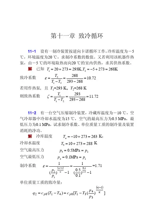
第十一章 致冷循环11-1 设有一制冷装置按逆向卡诺循环工作,冷库温度为-5 ℃,环境温度为20 ℃,求制冷系数的数值。
又若利用该机器作热泵,由-5 ℃的环境取热而向20 ℃的室内供热,求其供热系数。
解 已知 K 2682735,K 2932732021=+−==+=T T 致冷系数 72.10268293268212=−=−=T T T ε 若用作热泵, 且 T 1=293 K ,T 2=268 K则致热系数 72.11268293293211=−=−=T T T ζ11-2 有一台空气压缩制冷装置,冷藏库温度为-10 ℃,空气冷却器中冷却水温度为15 ℃,空气的最高压力为0.5 MPa ,最低压力为0.1 MPa ,试求制冷系数、单位质量工质的制冷量及装置消耗的净功。
解 冷库温度 K ; 263273104=+−=T 冷却水温度 K 288273103=+=T 空气最高压力 23MPa 5.0p p ==空气最低压力 14MPa 1.0p p ==制冷系数 ()1)1.05.0(11)(14.14.0112−=−=−κκεp p =1.71 单位质量工质的致冷量:()])([)(1343104102κκ−−=−=p pT T c T T c q p p·170· 制冷循环kJ/kg 49.81])5.01.0(288263[004.14.14.0=×−×=装置消耗的净功: kJ/kg 6.4771.149.8120===εq w11-3 有一台空气压缩制冷装置,冷藏库温度为-10 ℃,冷却器中冷却水温度为20 ℃,空气的最高压力为0.4 MPa ,最低压力为0.1MPa 。
若装置的制冷量为150 kW ,试求带动制冷装置所需的功率、冷却水带走的热量、装置中空气的流量以及膨胀机和压气机的功率。
解 T 1=263 K ;T 3=293 K ;p 1=p 4=0.1 MPa ;p 2=p 3=0.4 MPa 已知装置的致冷量 Q 2=150 kW 则装置循环的致冷系数()058.21)1.04.0(11)(14.14.0132=−=−=−κκεp p 装置所需的功率: kW 89.72058.21502===εQ P &冷却水带走的热量:kW 89.222289.721502=+=+=P Q Q &&单位质量工质的致冷量:()h/kgkW 36018.0kJ/kg 10.66])4.01.0(293263[004.1])([)(4.1/4.013431412⋅==−==−=−−κκp p T T c T T c q po po 所以空气的流量为:kg/h 981501836.015022m ===q Q q制冷循环·171·膨胀机的功率为:()kW218kJ/h 7848])4.01.0(1[293004.19815])([)(4.14.013433m 43m m ==−×××=−=−==−κκp pT T c q T T c q w q P po po e e压气机的功率为:()kW84.290kJ/h 10047.1]1.04.01[263004.19815])([)(64.14.011211m 21m m =×−=⎟⎠⎞⎜⎝⎛−×××=−=−==−κκp pT T c q T T c q w q P po po c c11-4 按上题所述条件,若压气机绝热效率为0.8,膨胀机效率为0.85,试求装置消耗的功率及制冷系数。
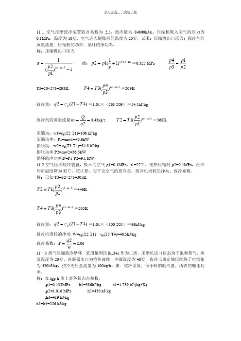
11-1空气压缩致冷装置致冷系数为2.5,致冷量为84600kJ/h ,压缩机吸入空气的压力为0.1MPa ,温度为-10℃,空气进入膨胀机的温度为20℃,试求:压缩机出口压力;致冷剂的质量流量;压缩机的功率;循环的净功率。
解:压缩机出口压力1)12(1/)1(-=-k k p p ε 故:))1/(()11(12-+=k k p p ε=0.325 MPa 2134p p p p = T3=20+273=293K k k p p T T /)1()34(34-==209K 致冷量:)41(2T T c q p -==1.01×(263-209)=54.5kJ/kg 致冷剂的质量流量==2q Q m 0.43kg/s k k p p T T /)1()12(12-==368K 压缩功:w1=c p (T2-T1)=106 kJ/kg压缩功率:P1=mw1=45.6kW膨胀功:w2= c p (T3-T4)=84.8 kJ/kg膨胀功率:P2=mw2=36.5kW循环的净功率:P=P1-P2=9.1 KW11-2空气压缩致冷装置,吸入的空气p1=0.1MPa ,t1=27℃,绝热压缩到p2=0.4MPa ,经冷却后温度降为32℃,试计算:每千克空气的致冷量;致冷机消耗的净功;致冷系数。
解:已知T3=32+273=305Kk k p p T T /)1()12(12-==446K k k p p T T /)1()34(34-==205K 致冷量:)41(2T T c q p -==1.01×(300-205)=96kJ/kg致冷机消耗的净功: W=c p (T2-T1)-c p (T3-T4)=46.5kJ/kg 致冷系数:==wq 2ε 2.06 11-3蒸气压缩致冷循环,采用氟利昂R134a 作为工质,压缩机进口状态为干饱和蒸气,蒸发温度为-20℃,冷凝器出口为饱和液体,冷凝温度为40℃,致冷工质定熵压缩终了时焓值为430kJ/kg ,致冷剂质量流量为100kg/h 。
第十一章自我测验题1、298K,101300Pa时有下列放热反应,指明反应热效应中哪些可称为标准生成焓(l);(2);(3);(4)o2、反应的热效应Qp>0,达平衡时,问下列情况下平衡是否被破坏?Kp是否变化?反应向何方向进行?(1)增加压力;(2)减少二氧化氮的分压力;(3)增加氧气的分压力;(4)升温;(5)增加二氧化氮的浓度;(6)加人催化剂。
3、某一反应的标准吉布斯函数变化大于0,能否说明该反应不能自发进行?为什么?4、碳的气化反应,试问:(1)达平衡时有人说,有人则说,究竟哪个对?(2)这时,,还是?5、确定气态丁烷在298K和101325Pa下的定压燃烧反应热效应。
假定生成物中的水为液相,且各物质的标准生成焓为:,,。
6、求下列反应在101300Pa及600K下的热效应已知有关参数及各气体的摩尔热容为:,7、计算丙烷在过量空气量为20%下完全燃烧时的空气燃料比。
空气中氮、氧的物质的量之比为3.76。
已知丙烷在空气量为理论值时完全燃烧的方程为:8、丙烷燃烧后的干燃气摩尔分数为:二氧化碳11.5%,氧气2.7%,一氧化碳0.7%,氮气85.1%。
试确定空燃比,过量空气系数,并写出此反应方程。
9、在101300Pa下测得四氧化二氮在60℃时有50%离解成二氧化氮,计算反应的K p10、已知气相反应,在某温度时的平衡常数为29,求同一温度下:(1)反应的平衡常数;(2)反应的平衡常数。
11、在1立方分米的容器内应放入多少mol的PCl5才可得到100mol的Cl2?已知在250℃时的平衡常数为1.78。
第十一章自测题答案1、反应(2)的反应热效应为二氧化碳的标准生成焓反应(4)的反应热效应为水蒸气的标准生成焓2、(1)平衡被破坏,Kp不变,反应向正方向进行;(2)平衡被破坏,Kp不变,反应向正方向进行;(3)平衡被破坏,Kp不变,反应向正方向进行;(4)平衡被破坏,Kp增大,反应向正方向进行;(5)平衡被破坏,Kp不变,反应向反方向进行;(6)平衡被破坏,Kp增大,反应向正方向进行;3、不能。
第十一章 制冷循环1、家用冰箱的使用说明书上指出,冰箱应放置在通风处,并距墙壁适当距离,以及不要把冰箱温度设置过低,为什么?答:为了维持冰箱的低温,需要将热量不断地传输到高温热源(环境大气),如果冰箱传输到环境大气中的热量不能及时散去,会使高温热源温度升高,从而使制冷系数降低,所以为了维持较低的稳定的高温热源温度,应将冰箱放置在通风处,并距墙壁适当距离。
在一定环境温度下,冷库温度愈低,制冷系数愈小,因此为取得良好的经济效益,没有必要把冷库的温度定的超乎需要的低。
2、为什么压缩空气制冷循环不采用逆向卡诺循环?答:由于空气定温加热与定温放热不易实现,故不能按逆向卡诺循环运行。
在压缩空气制冷循环中,用两个定压过程来代替逆向卡诺循环的两个定温过程。
3、压缩蒸气制冷循环采用节流阀来代替膨胀机,压缩空气制冷循环就是否也可以采用这种方法?为什么?答:压缩空气制冷循环不能采用节流阀来代替膨胀机。
工质在节流阀中的过程就是不可逆绝热过程,不可逆绝热节流熵增大,所以不但减少了制冷量也损失了可逆绝热膨胀可以带来的功量。
而压缩蒸气制冷循环在膨胀过程中,因为工质的干度很小,所以能得到的膨胀功也极小。
而增加一台膨胀机,既增加了系统的投资,又降低了系统工作的可靠性。
因此,为了装置的简化及运行的可靠性等实际原因采用节流阀作绝热节流。
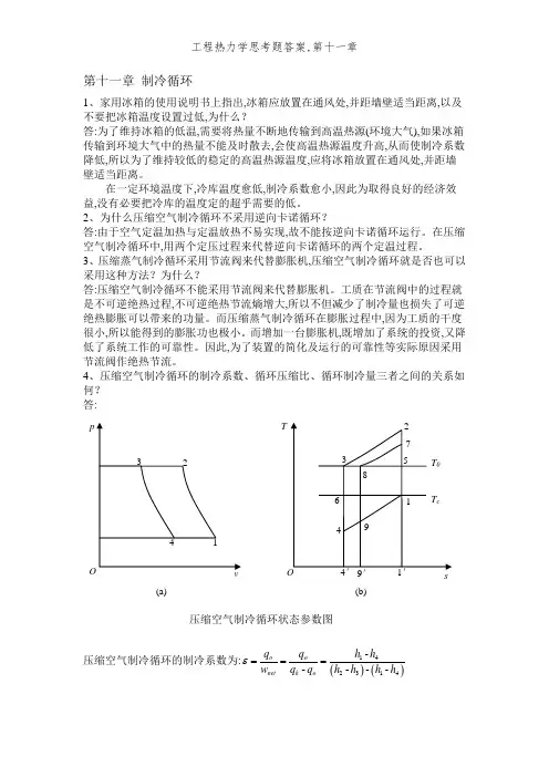
4、压缩空气制冷循环的制冷系数、循环压缩比、循环制冷量三者之间的关系如何?答:压缩空气制冷循环的制冷系数为:()()142314-----o o net k o q q h h w q q h h h h ε===(a) (b) 压缩空气制冷循环状态参数图空气视为理想气体,且比热容为定值,则:()()142314T T T T T T ε-=--- 循环压缩比为:21p p π=过程1-2与3-4都就是定熵过程,因而有:1322114k k T T P T P T -⎛⎫== ⎪⎝⎭ 代入制冷系数表达式可得:111k k επ-=- 由此式可知,制冷系数与增压比有关。
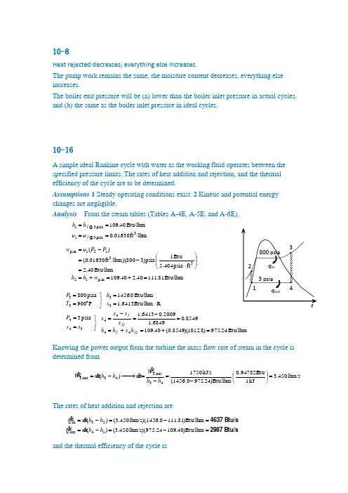
10-8Heat rejected decreases; everything else increases.The pump work remains the same, the moisture content decreases, everything else increases.The boiler exit pressure will be (a) lower than the boiler inlet pressure in actual cycles, and (b) the same as the boiler inlet pressure in ideal cycles.10-16A simple ideal Rankine cycle with water as the working fluid operates between the specified pressure limits. The rates of heat addition and rejection, and the thermal efficiency of the cycle are to be determined.Assumptions 1 Steady operating conditions exist. 2 Kinetic and potential energy changes are negligible.Analysis From the steam tables (Tables A-4E, A-5E, and A-6E),Btu/lbm81.11140.240.109Btu/lbm40.2ft psia 5.404Btu 1 psia )3800)(/lbm ft 01630.0()(/lbmft 01630.0Btu/lbm40.109in p,1233121in p,3psia 3 @1psia 3 @1=+=+==⎪⎪⎭⎫⎝⎛⋅-=-=====w h h P P w h h f f v v vBtu/lbm 24.975)8.1012)(8549.0(40.1098549.06849.12009.06413.1 psia 3RBtu/lbm 6413.1Btu/lbm0.1456F 900psia 80044443443333=+=+==-=-=⎭⎬⎫==⋅==⎭⎬⎫︒==fgf fg fh x h h s s s x s s P s h T PKnowing the power output from the turbine the mass flow rate of steam in the cycle is determined fromlbm/s 450.3kJ 1Btu 0.94782)Btu/lbm 24.975(1456.0kJ/s 1750)(43out T,43out T,=⎪⎭⎫ ⎝⎛-=-=−→−-=h h W m h h m WThe rates of heat addition and rejection areBtu/s2987Btu/s 4637=-=-==-=-=Btu/lbm )40.109.24lbm/s)(975 450.3()(Btu/lbm )81.1110.6lbm/s)(145 450.3()(14out 23inh h m Q h h m Qand the thermal efficiency of the cycle is35.6%==-=-=3559.04637298711inout thQ Q η10-24A single-flash geothermal power plant uses hot geothermal water at 230ºC as the heatsource. The mass flow rate of steam through the turbine, the isentropic efficiency of the turbine, the power output from the turbine, and the thermal efficiency of the plant are to be determined.Assumptions 1 Steady operating conditions exist. 2 Kinetic and potential energy changes are negligible.Analysis (a ) We use properties of water for geothermal water (Tables A-4 through A-6)kJ/kg 14.990kP a 500 14.9900C 23022122111=-=⎭⎬⎫====⎭⎬⎫=︒=fg f h h h x h h P h x T The mass flow rate of steam through the turbine is===kg/s) 230)(1661.0(123m x m (b ) Turbine:kJ/kg 7.2344)1.2392)(90.0(81.19190.0kPa 10kJ/kg 3.2160kPa 10K kJ/kg 8207.6kJ/kg1.27481kPa 500444443443333=+=+=⎭⎬⎫===⎭⎬⎫==⋅==⎭⎬⎫==fg f s h x h h x P h s s P s h x P0.686=--=--=3.21601.27487.23441.27484343s T h h h h η (c ) The power output from the turbine iskW 15,410=-=-=kJ/kg )7.23448.1kJ/kg)(274 38.20()(433out T,h h mW (d ) We use saturated liquid state at the standard temperature for dead state enthalpykJ/kg 83.1040C 25000=⎭⎬⎫=︒=h x TkW 622,203kJ/kg )83.104.14kJ/kg)(990 230()(011in=-=-=h h m E7.6%====0.0757622,203410,15inout T,thE W η10-36An ideal reheat Rankine with water as the working fluid is considered. The temperatures at the inlet of both turbines, and the thermal efficiency of the cycle are to be determined. Assumptions 1 Steady operating conditions exist. 2 Kinetic and potential energy changes are negligible.Analysis From the steam tables (Tables A-4, A-5, and A-6),kJ/kg87.19806.781.191kJ/kg06.7m kPa 1kJ 1 kPa )107000)(/kg m 001010.0()(/kgm 001010.0kJ/kg81.191in p,1233121in p,3kPa 10 @1kPa 10 @1=+=+==⎪⎭⎫ ⎝⎛⋅-=-=====w h h P P w h h f f v v vC373.3︒==⎭⎬⎫==⋅=+=+==+=+=⎭⎬⎫==33433444444kJ/kg5.3085kP a 7000K kJ/kg 3385.6)6160.4)(93.0(0457.2kJ/kg0.2625)5.2047)(93.0(87.720 93.0kP a 800T h s s P s x s s h x h h x P fg f fg fC416.2︒==⎭⎬⎫==⋅=+=+==+=+=⎭⎬⎫==55655666666kJ/kg0.3302kP a 800K kJ/kg 6239.7)4996.7)(93.0(6492.0kJ/kg 4.2416)1.2392)(93.0(81.191 90.0kP a 10T h s s P s x s s h x h h x P fg f fg fThus, kJ/kg6.222481.1914.2416kJ/kg 6.35630.26250.330287.1985.3085)()(16out 4523in =-=-==-+-=-+-=h h q h h h h qand37.6%==-=-=3757.06.35636.222411in out th q q η10-38A steam power plant that operates on a reheat Rankine cycle is considered. The condenser pressure, the net power output, and the thermal efficiency are to be determined.Assumptions 1 Steady operating conditions exist. 2 Kinetic and potential energy changes are negligible.Analysis (a()()()()()()3)(Eq. 2.335885.02.33582) (Eq. ?1) (Eq.95.0?K kJ/kg 2815.7kJ/kg2.3358C 450 MP a 2kJ/kg3.30271.29485.347685.05.3476kJ/kg 1.2948MP a 2K kJ/kg 6317.6kJ/kg5.3476C 550 MP a 5.12665566565656666655554334434343443333s s T sT s s T sT s s h h h h h h h h h h s s P h x P s h T P h h h h h h h h h s s P s h T P --=--=−→−--==⎭⎬⎫===⎭⎬⎫==⋅==⎭⎬⎫︒===--=--=→--==⎭⎬⎫==⋅==⎭⎬⎫︒==ηηηη The pressure at state 6 may be determined by a trial-error approach from the steam tables or by using EES from the above three equations:P 6 = 9.73 kPa , h 6 = 2463.3 kJ/kg,(b ) Then,()()()()kJ/kg59.20302.1457.189kJ/kg14.020.90/m kP a 1kJ 1kP a 73.912,500/kg m 0.00101//kgm 001010.0kJ/kg57.189in ,123121in ,3kPa 10 @1kPa 73.9 @1=+=+==⎪⎪⎭⎫⎝⎛⋅-=-=====p pp f f w h h P P w h h ηv v v Cycle analysis:()()kW 10,242==-==-=-==-+-=-+-=kg 2273.7)kJ/-.8kg/s)(3603 7.7()(kJ/kg7.227357.1893.2463kJ/kg 8.36033.24632.335859.2035.3476out in net16out 4523in q q m W h h q h h h h q (c ) The thermal efficiency is36.9%==-=-=369.0kJ/kg3603.8kJ/kg2273.711in out th q q η。
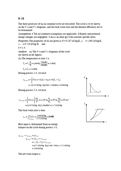
9-13The three processes of an air-standard cycle are described. The cycle is to be shown on the P-v and T-s diagrams, and the back work ratio and the thermal efficiency are to be determined.Assumptions 1 The air-standard assumptions are applicable. 2 Kinetic and potential energy changes are negligible. 3 Air is an ideal gas with constant specific heats. Properties The properties of air are given as R = 0.287 kJ/kg.K, c p = 1.005 kJ/kg.K, c v = 0.718 kJ/kg·K, and k = 1.4.Analysis (a) The P -v and T -s diagrams of the cycle are shown in the figures. (b) The temperature at state 2 is K 2100kP a100kP a 700K) 300(1212===P P T TK 210023==T TDuring process 1-3, we havekJ/kg516.600)K 21K)(300kJ/kg 287.0()()(3131113,13=-⋅-=--=--=-=⎰-T T R P Pd w in V V vDuring process 2-3, we havekJ/kg8.1172n7K)(2100)Kl kJ/kg 287.0(7ln 7ln ln22233232,32=⋅======⎰⎰-RT RT RT d RTPd w out V VV V v Vv The back work ratio is then0.440===--kJ/kg8.1172kJ/kg6.516,32,13outin bw w w rHeat input is determined from an energybalance on the cycle during process 1-3,kJ/kg2465kJ/kg 1172.8300)K)(2100kJ/kg 718.0()(,3213,3231,3131,32,31=+-⋅=+-=+∆=-∆=--------outv outin out in w T T c w u q u w qThe net work output issvkJ/kg 2.6566.5168.1172,13,32=-=-=--in out net w w w(c) The thermal efficiency is then26.6%====266.0kJ2465kJ656.2in net th q w η9-21An air-standard cycle executed in a piston-cylinder system is composed of threespecified processes. The cycle is to be sketcehed on the P -v and T -s diagrams; the heat and work interactions and the thermal efficiency of the cycle are to bedetermined; and an expression for thermal efficiency as functions of compression ratio and specific heat ratio is to be obtained.Assumptions 1 The air-standard assumptions are applicable. 2 Kinetic and potential energy changes are negligible. 3 Air is an ideal gas with constant specific heats. Properties The properties of air are given as R = 0.3 kJ/kg·K and c v = 0.3 kJ/kg·K. Analysis (a) The P -v and T -s diagrams of the cycle are shown in the figures. (b) Noting that1.4297.00.1KkJ/kg 0.13.07.0===⋅=+=+=vv c c k R c c p pProcess 1-2: Isentropic compressionK 4.584)5)(K 293(429.01112112===⎪⎪⎭⎫ ⎝⎛=--k k r T T T vvkJ/kg 204.0=-⋅=-=-K )2934.584)(K kJ/kg 7.0()(12in 2,1T T c w v0=-21qFrom ideal gas relation,2922)5)(4.584(3212323==−→−===T r T T v v v v Process 2-3: Constant pressure heat additionkJ/kg701.3=-⋅=-=-==⎰-K )4.5842922)(K kJ/kg 3.0()()(2323232out 3,2T T R P Pd w v v vskJ/kg2338=-⋅=-=∆=∆+=----K )4.5842922)(K kJ/kg 1()(233232,32in 3,2T T c h u w q p outProcess 3-1: Constant volume heat rejectionkJ/kg 1840.3=⋅=-=∆=--K 293)-K)(2922kJ/kg 7.0()(1331out 1,3T T c u q v0=-13w(c) Net work isK kJ/kg 3.4970.2043.701in 2,1out 3,2net ⋅=-=-=--w w wThe thermal efficiency is then21.3%====213.0kJ2338kJ497.3in net th q w η9-32The two isentropic processes in an Otto cycle are replaced with polytropic processes.The heat added to and rejected from this cycle, and the cycle’s thermal efficiency are to be determined.Assumptions 1 The air-standard assumptions are applicable. 2 Kinetic and potential energy changes are negligible. 3 Air is an ideal gas with constant specific heats. Properties The properties of air at room temperature are R = 0.287 kPa·m 3/kg·K, c p = 1.005 kJ/kg·K, c v = 0.718 kJ/kg·K, and k = 1.4 (Table A-2a). Analysis The temperature at the end of the compression isK 4.537K)(8) 288(13.11112112===⎪⎪⎭⎫ ⎝⎛=---n n r T T T vvAnd the temperature at the end of the expansion isK 4.78981K) 1473(113.11314334=⎪⎭⎫⎝⎛=⎪⎭⎫ ⎝⎛=⎪⎪⎭⎫ ⎝⎛=---n n r T T T vvThe integral of the work expression for the polytropic compression giveskJ/kg 6.238)18(13.1K) K)(288kJ/kg 287.0(1113.1121121=--⋅=⎥⎥⎦⎤⎢⎢⎣⎡-⎪⎪⎭⎫ ⎝⎛-=---n n RT w vvSimilarly, the work produced during the expansion iskJ/kg 0.65418113.1K) K)(1473kJ/kg 287.0(1113.1143343=⎥⎥⎦⎤⎢⎢⎣⎡-⎪⎭⎫⎝⎛-⋅-=⎥⎥⎦⎤⎢⎢⎣⎡-⎪⎪⎭⎫ ⎝⎛--=---n n RT w vv Application of the first law to each of the four processes giveskJ/kg 53.59K )2884.537)(K kJ/kg 718.0(kJ/kg 6.238)(122121=-⋅-=--=--T T c w q v kJ/kg 8.671K )4.5371473)(K kJ/kg 718.0()(2332=-⋅=-=-T T c q vkJ/kg 2.163K )4.7891473)(K kJ/kg 718.0(kJ/kg 0.654)(434343=-⋅-=--=--T T c w q vkJ/kg 0.360K )2884.789)(K kJ/kg 718.0()(1414=-⋅=-=-T T c q vThe head added and rejected from the cycle arekJ/kg419.5kJ/kg 835.0=+=+==+=+=----0.36053.592.1638.6711421out 4332in q q q q q qThe thermal efficiency of this cycle is then0.498=-=-=0.8355.41911in out th q q η9-37An ideal Otto cycle with air as the working fluid has a compression ratio of 8. Theamount of heat transferred to the air during the heat addition process, the thermal efficiency, and the thermal efficiency of a Carnot cycle operating between the same temperature limits are to be determined. Assumptions 1 The air-standard assumptions are applicable. 2 Kinetic and potential energy changes are negligible. 3 Air is an ideal gas with variable specific heats.Properties The properties of air are given in Table A-17E. Analysis (a) Process 1-2: isentropic compression.32.144Btu/lbm92.04R 540111==−→−=r u T v()Btu/lbm 11.28204.1832.144811212222=−→−====u r r r r v v v v v Process 2-3: v = constant heat addition.Btu/lbm241.42=-=-===−→−=28.21170.452419.2Btu/lbm452.70R 240023333u u q u T in r vvP(b) Process 3-4: isentropic expansion.()()Btu/lbm 205.5435.19419.28434334=−→−====u r r r r v v v v v Process 4-1: v = constant heat rejection.Btu/lbm 50.11304.9254.20514out =-=-=u u q53.0%=-=-=Btu/lbm241.42Btu/lbm113.5011in out th q q η (c) The thermal efficiency of a Carnot cycle operating between the same temperature limits is 77.5%=-=-=R2400R54011C th,H L T T η9-40The expressions for the maximum gas temperature and pressure of an ideal Otto cycleare to be determined when the compression ratio is doubled.Assumptions 1 The air-standard assumptions are applicable. 2 Kinetic and potential energy changes are negligible. 3 Air is an ideal gas with constant specific heats. Analysis The temperature at the end of the compression varies with the compression ratio as1112112--=⎪⎪⎭⎫⎝⎛=k k r T T T v vsince T 1 is fixed. The temperature rise during thecombustion remains constant since the amount of heat addition is fixed. Then, the maximum cycle temperature is given by11in 2in 3//-+=+=k r T c q T c q T v vThe smallest gas specific volume during the cycle isr13v v =When this is combined with the maximum temperature, the maximum pressure is given by ()11in 1333/-+==k r T c qRrRT P v v v9-47An ideal diesel cycle has a compression ratio of 20 and a cutoff ratio of 1.3. The maximum temperature of the air and the rate of heat addition are to be determined. Assumptions 1 The air-standard assumptions are applicable. 2 Kinetic and potential energy changes are negligible. 3 Air is an ideal gas with constant specific heats. Properties The properties of air at room temperature are c p = 1.005 kJ/kg·K, c v = 0.718 kJ/kg·K, R = 0.287 kJ/kg·K, and k = 1.4 (Table A-2a). Analysis()K 6.95420K) 288(14.11112112===⎪⎪⎭⎫ ⎝⎛=---k k r T T T vvK 1241===⎪⎪⎭⎫ ⎝⎛=K)(1.3) 6.954(22323c r T T T vv Combining the first law as applied to the various processes with the process equations gives6812.0)13.1(4.113.12011)1(1114.111.41th =---=---=--c k c k r k r r ηAccording to the definition of the thermal efficiency,kW 367===0.6812kW 250th net inηW Q9-59An ideal dual cycle has a compression ratio of 15 and cutoff ratio of 1.4. The net work,heat addition, and the thermal efficiency are to be determined.Assumptions 1 The air-standard assumptions are applicable. 2 Kinetic and potential energy changes are negligible. 3 Air is an ideal gas with constant specific heats. Properties The properties of air at room temperature are R = 0.3704 psia·ft 3/lbm.R (Table A-1E), c p = 0.240 Btu/lbm·R, c v = 0.171 Btu/lbm·R, and k = 1.4 (Table A-2Ea).Analysis Working around the cycle, the germane properties at the various states are()R 158015R) 535(14.11112112===⎪⎪⎭⎫ ⎝⎛=---k k r T T T vvout()psia 2.62915psia) 2.14(4.112112===⎪⎪⎭⎫ ⎝⎛=k kr P P P vvpsia 1.692psia) 2.629)(1.1(23====P r P P p xR 1738psia 629.2psia 692.1R) 1580(22=⎪⎪⎭⎫ ⎝⎛=⎪⎪⎭⎫ ⎝⎛=PP T T xxR 2433R)(1.4) 1738(33===⎪⎪⎭⎫⎝⎛=c x xx r T T T vvR 2.942151.4R) 2433(14.11314334=⎪⎭⎫⎝⎛=⎪⎪⎭⎫ ⎝⎛=⎪⎪⎭⎫ ⎝⎛=---k c k rr T T T vvApplying the first law to each of the processes givesBtu/lbm 7.178R )5351580)(R Btu/lbm 171.0()(1221=-⋅=-=-T T c w v Btu/lbm 02.27R )15801738)(R Btu/lbm 171.0()(22=-⋅=-=-T T c q x x vBtu/lbm 8.166R )17382433)(R Btu/lbm 240.0()(33=-⋅=-=-x p x T T c qB t u /l b 96.47R )17382433)(R Btu/lbm 171.0(Btu/lbm 8.166)(333=-⋅-=--=--x x x T T c q w vBtu/lbm 9.254R )2.9422433)(R Btu/lbm 171.0()(4343=-⋅=-=-T T c w vThe net work of the cycle isBtu/lbm 124.2=-+=-+=---7.17896.479.25421343net w w w w x and the net heat addition isBtu/lbm 193.8=+=+=--8.16602.2732in x x q q q Hence, the thermal efficiency is0.641===Btu/lbm193.8Btu/lbm124.2in net th q w η9-61An expression for cutoff ratio of an ideal diesel cycle is to be developed.Assumptions 1 The air-standard assumptions are applicable. 2 Kinetic and potentialenergy changes are negligible. 3 Air is an ideal gas with constant specific heats. Analysis Employing the isentropic process equations,112-=k rT Toutwhile the ideal gas law gives1123T r r r T T k c c -==When the first law and the closed system work integral is applied to the constant pressure heat addition, the result is)()(111123in T r T r r c T T c q k k c p p ---=-=When this is solved for cutoff ratio, the result is11in1T r c q r k p c -+=9-81A simple ideal Brayton cycle with air as the working fluid has a pressure ratio of 10. The air temperature at the compressor exit, the back work ratio, and the thermal efficiency are to be determined.Assumptions 1 Steady operating conditions exist. 2 The air-standard assumptions are applicable. 3 Kinetic and potential energy changes are negligible. 4 Air is an ideal gas with variable specific heats.Properties The properties of air are given in Table A-17E. Analysis (a ) Noting that process 1-2 is isentropic,T h P r 11112147=−→−==520R124.27Btu /lbm .()()Btu/lbm 240.11 147.122147.110221212==−→−===h T P P P P r r R 996.5(b ) Process 3-4 is isentropic, and thus()Btu/lbm38.88283.26571.504Btu/lbm115.8427.12411.240Btu/lbm 265.834.170.1741010.174Btu/lbm 504.71R 200043out T,12inC,43433343=-=-==-=-==−→−=⎪⎭⎫⎝⎛====−→−=h h w h h w h P P P P P h T r r rThen the back-work ratio becomess200052048.5%===Btu/lbm238.88Btu/lbm115.84outT,in C,bw w w r(c ) 46.5%====-=-==-=-=Btu/lbm264.60Btu/lbm123.04Btu/lbm123.0484.11588.238Btu/lbm264.6011.24071.504inout net,th in C,out T,out net,23in q w w w w h h q η9-87A simple ideal Brayton cycle with air as the working fluid has a pressure ratio of 10.The air temperature at the compressor exit, the back work ratio, and the thermal efficiency are to be determined.Assumptions 1 Steady operating conditions exist. 2 The air-standard assumptions are applicable. 3 Kinetic and potential energy changes are negligible. 4 Air is an ideal gas with variable specific heats.Properties The properties of air are given in Table A-17E. Analysis (a ) Noting that process 1-2 is isentropic,T h P r 11112147=−→−==520R124.27Btu /lbm .()()Btu/lbm 240.11 147.122147.110221212==−→−===h T P P P P r r R 996.5(b ) Process 3-4 is isentropic, and thus()Btu/lbm38.88283.26571.504Btu/lbm115.8427.12411.240Btu/lbm 265.834.170.1741010.174Btu/lbm 504.71R 200043out T,12inC,43433343=-=-==-=-==−→−=⎪⎭⎫⎝⎛====−→−=h h w h h w h P P P P P h T r r rThen the back-work ratio becomes48.5%===Btu/lbm238.88Btu/lbm115.84outT,in C,bw w w rs2000520(c ) 46.5%====-=-==-=-=Btu/lbm264.60Btu/lbm123.04Btu/lbm123.0484.11588.238Btu/lbm264.6011.24071.504inout net,th in C,out T,out net,23in q w w w w h h q η(d) The expression for the cycle thermal efficiency is obtained as follows:⎪⎭⎫ ⎝⎛---⎪⎭⎫ ⎝⎛-=⎪⎭⎫⎝⎛---=⎪⎪⎭⎫ ⎝⎛---=-⎪⎪⎭⎫ ⎝⎛--=---=----=-==-----------1111111111111111111231223in in 2,1out 3,2in net th 11)1(11111)1(11)1(1)1(1)()()()()(k k p k p k p k k v p k k p k v p p v r r k k r r k c R r T T r k c R r r T c r T T r T c c R r T r rT c T r T c c RT T c T T c T T R q w w q w η since 111kc c c c c c R p v p v p p -=-=-=。
1-2There is no truth to his claim. It violates the second law of thermodynamics. 1-14A gas tank is being filled with gasoline at a specified flow rate. Based on unit considerations alone, a relation is to be obtained for the filling time. Assumptions Gasoline is an incompressible substance and the flow rate is constant.Analysis The filling time depends on the volume of the tank and the discharge rate of gasoline. Also, we know that the unit of time is ‘seconds’. Therefore, the independent quantities should be arranged such that we end up with the unit of seconds. Putting the given information into perspective, we havet [s] [L], and [L/s}It is obvious that the only way to end up with the unit “s” for time is to divide the tank volume by the discharge rate. Therefore, the desired relation is Discussion Note that this approach may not work for cases that involve dimensionless (and thus unitless) quantities.1-25A process during which the temperature remains constant is called isothermal; a process during which the pressure remains constant is called isobaric; and a process during which the volume remains constant is called isochoric.1-38The change in water temperature given in F unit is to be converted to C, K and R units.Analysis Using the conversion relations between the various temperature scales,1-49The pressure in a pressurized water tank is measured by a multi-fluid manometer. The gage pressure of air in the tank is to be determined. Assumptions The air pressure in the tank is uniform (i.e., its variation with elevation is negligible due to its low density), and thus we can determine the pressure at the air-water interface.Properties The densities of mercury, water, and oil are given to be 13,600, 1000, and 850 kg/m3, respectively.Analysis Starting with the pressure at point 1 at the air-water interface, and moving along the tube by adding (as we go down) or subtracting (as we go up) th e terms until we reach point 2, and setting the result equal to P atm since the tube is open to the atmosphere givesSolving for P1,or,Noting that P1,gage = P1 - P atm and substituting,Discussion Note that jumping horizontally from one tube to the next and realizing that pressure remains the same in the same fluid simplifies the analysis greatly.1-55The pressure in chamber 1 of the two-piston cylinder shown in the figure is to be determined.Analysis Summing the forces acting on the piston in the vertical direction givesF1F2F3which when solved for P1 givessince the areas of the piston faces are given bythe above equation becomes1-63A gas contained in a vertical piston-cylinder device is pressurized by a spring and by the weight of the piston. The pressure of the gas is to be determined. Analysis Drawing the free body diagram of thepiston and balancing the vertical forces yieldF springP atmPW = mgThus,1-74Fresh and seawater flowing in parallel horizontal pipelines are connected to each other by a double U-tube manometer. The pressure difference between the two pipelines is to be determined.Assumptions 1 All the liquids areincompressible. 2 The effect of aircolumn on pressure is negligible.FreshWaterh wh seah airSeaWaterMercuryAirh HgProperties The densities of seawaterand mercury are given to be sea =1035 kg/m3 and Hg = 13,600 kg/m3.We take the density of water to be w=1000 kg/m3.Analysis Starting with the pressurein the fresh water pipe (point 1) andmoving along the tube by adding (aswe go down) or subtracting (as wego up) the terms until we reach thesea water pipe (point 2), and settingthe result equal to P2givesRearranging and neglecting the effect of air column on pressure, Substituting,Therefore, the pressure in the fresh water pipe is 3.39 kPa higher than the pressure in the sea water pipe.Discussion A 0.70-m high air column with a density of 1.2 kg/m3 corresponds to a pressure difference of 0.008 kPa. Therefore, its effect on the pressure difference between the two pipes is negligible.1-83A multi-fluid container is connected to a U-tube. For the given specific gravities and fluid column heights, the gage pressure at A and the height of a mercury column that would create the same pressure at A are to be determined.Assumptions 1 All the liquids areincompressible. 2 The multi-fluidcontainer is open to the atmosphere.A90 cm70 cm30 cm15 cmGlycerinSG=1.26OilSG=0.90Water20 cmProperties The specific gravities aregiven to be 1.26 for glycerin and 0.90for oil. We take the standard density ofwater to be w=1000 kg/m3, and thespecific gravity of mercury to be 13.6.Analysis Starting with the atmosphericpressure on the top surface of thecontainer and moving along the tube byadding (as we go down) or subtracting(as we go up) the terms until we reachpoint A, and setting the result equal toP A giveRearranging and using the definition of specific gravity,orSubstituting,The equivalent mercury column height isDiscussion Note that the high density of mercury makes it a very suitable fluid for measuring high pressures in manometers.1-109The gage pressure in a pressure cooker is maintained constant at 100 kPa by a petcock. The mass of the petcock is to be determined.Assumptions There is no blockage of the pressure release valve.W = mgP atmPAnalysis Atmospheric pressure is acting on allsurfaces of the petcock, which balances itself out.Therefore, it can be disregarded in calculations ifwe use the gage pressure as the cooker pressure. Aforce balance on the petcock (F y = 0) yields1-119A relation for the air drag exerted on a car is to be obtained in terms of on the drag coefficient, the air density, the car velocity, and the frontal area of the car.Analysis The drag force depends on a dimensionless drag coefficient, the air density, the car velocity, and the frontal area. Also, the unit of force F is newton N, which is equivalent to kgm/s2. Therefore, the independent quantities should be arranged such that we end up with the unit kgm/s2 for the drag force. Putting the given information into perspective, we haveF D [ kgm/s2] C Drag [], A front [m2],[kg/m3], and V [m/s]It is obvious that the only way to end up with the unit “kgm/s2” for drag force is to multiply mass with the square of the velocity and the fontal area, with the drag coefficient serving as the constant of proportionality. Therefore, the desired relation isDiscussion Note that this approach is not sensitive to dimensionless quantities, and thus a strong reasoning is required.。
第十一章制冷循环1.家用冰箱的使用说明书上指出,冰箱应放置在通风处,并距墙壁适当距离,以及不要把冰箱温度设置过低,为什么答:为了维持冰箱的低温,需要将热量不断地传输到高温热源环境大气,如果冰箱传输到环境大气中的热量不能及时散去,会使高温热源温度升高,从而使制冷系数降低,所以为了维持较低的稳定的高温热源温度,应将冰箱放置在通风处,并距墙壁适当距离.在一定环境温度下,冷库温度愈低,制冷系数愈小,因此为取得良好的经济效益,没有必要把冷库的温度定的超乎需要的低.2.为什么压缩空气制冷循环不采用逆向卡诺循环答:由于空气定温加热和定温放热不易实现,故不能按逆向卡诺循环运行.在压缩空气制冷循环中,用两个定压过程来代替逆向卡诺循环的两个定温过程.3.压缩蒸气制冷循环采用节流阀来代替膨胀机,压缩空气制冷循环是否也可以采用这种方法为什么答:压缩空气制冷循环不能采用节流阀来代替膨胀机.工质在节流阀中的过程是不可逆绝热过程,不可逆绝热节流熵增大,所以不但减少了制冷量也损失了可逆绝热膨胀可以带来的功量.而压缩蒸气制冷循环在膨胀过程中,因为工质的干度很小,所以能得到的膨胀功也极小.而增加一台膨胀机,既增加了系统的投资,又降低了系统工作的可靠性.因此,为了装置的简化及运行的可靠性等实际原因采用节流阀作绝热节流.4.压缩空气制冷循环的制冷系数、循环压缩比、循环制冷量三者之间的关系如何 答:压缩空气制冷循环的制冷系数为:()()142314-----o o net k o q q h h w q q h h h h ε=== 空气视为理想气体,且比热容为定值,则:()()142314T T T T T T ε-=---循环压缩比为:21p p π=过程1-2和3-4都是定熵过程,因而有:1322114k kT T P T P T -⎛⎫==⎪⎝⎭ 代入制冷系数表达式可得:111k kεπ-=-由此式可知,制冷系数与增压比有关.循环压缩比愈小,制冷系数愈大,但是循环压缩比减小会导致膨胀温差变小从而使循环制冷量减小,如图b 中循环1-7-8-9-1的循环压缩比较循环1-2-3-4-1的小,其制冷量面积199′1′1小于循环1-2-3-4-1的制冷量面积144′1′1.T sO 4′ 9′1′Ov ab压缩空气制冷循环状态参数5.压缩空气制冷循环采用回热措施后是否提高其理论制冷系数能否提高其实际制冷系数为什么答:采用回热后没有提高其理论制冷系数但能够提高其实际制冷系数.因为采用回热后工质的压缩比减小,使压缩过程和膨胀过程的不可逆损失的影响减小,因此提高实际制冷系数.6.按热力学第二定律,不可逆节流必然带来做功能力损失,为什么几乎所有的压缩蒸气制冷装置都采用节流阀答:压缩蒸气制冷循环中,湿饱和蒸气在绝热膨胀过程中,因工质中液体的含量很大,故膨胀机的工作条件很差.为了简化设备,提高装置运行的可靠性,所以采用节流阀.7.参看图 5,若压缩蒸汽制冷循环按1-2-3-4-8-1 运行,循环耗功量没有变化,仍为h2-h1,而制冷量却从h1-h5.增大到h1-h8,显见是“有利”的.这种考虑可行么为什么答:过程4-8熵减小,必须放热才能实现.而4 点工质温度为环境温度T,要想放热达到温度Tc 8点,必须有温度低于Tc的冷源,这是不存在的.如果有,就不必压缩制冷了.8.作制冷剂的物质应具备哪些性质你如何理解限产直至禁用氟利昂类工质,如R11、R12答:制冷剂应具备的性质:对应于装置的工作温度,要有适中的压力;在工作温度下气化潜热要大;临界温度应高于环境温度;制冷剂在T-s 图上的上下界限线要陡峭;工质的三相点温度要低于制冷循环的下限温度;比体积要小;传热特性要好;溶油性好;无毒等.限产直至禁用R11 和R12 时十分必要的,因为这类物质进入大气后在紫外线作用下破坏臭氧层使得紫外线直接照射到地面,破坏原有的生态平衡.9.本章提到的各种制冷循环有否共同点若有是什么答:各种制冷循环都有共同点.从热力学第二定律的角度来看,无论是消耗机械能还是热能都是使熵增大,以弥补热量从低温物体传到高温物体造成的熵的减小,从而使孤立系统保持熵增大.10.为什么同一装置即可作制冷剂又可作热泵答:因为热泵循环与制冷循环的本质都是消耗高质能以实现热量从低温热源向高温热元的传输.热泵循环和制冷循环的热力学原理相同.。
工程热力学第三版课后习题答案工程热力学第三版课后习题答案【篇一:工程热力学课后答案】章)第1章基本概念⒈闭口系与外界无物质交换,系统内质量将保持恒定,那么,系统内质量保持恒定的热力系一定是闭口系统吗? 答:否。
当一个控制质量的质量入流率与质量出流率相等时(如稳态稳流系统),系统内的质量将保持恒定不变。
⒉有人认为,开口系统中系统与外界有物质交换,而物质又与能量不可分割,所以开口系不可能是绝热系。
这种观点对不对,为什么?答:不对。
“绝热系”指的是过程中与外界无热量交换的系统。
热量是指过程中系统与外界间以热的方式交换的能量,是过程量,过程一旦结束就无所谓“热量”。
物质并不“拥有”热量。
一个系统能否绝热与其边界是否对物质流开放无关。
⒊平衡状态与稳定状态有何区别和联系,平衡状态与均匀状态有何区别和联系?答:“平衡状态”与“稳定状态”的概念均指系统的状态不随时间而变化,这是它们的共同点;但平衡状态要求的是在没有外界作用下保持不变;而平衡状态则一般指在外界作用下保持不变,这是它们的区别所在。
⒋倘使容器中气体的压力没有改变,试问安装在该容器上的压力表的读数会改变吗?在绝对压力计算公式p?pb?pe(p?pb); p?pb?pv(p?pb)中,当地大气压是否必定是环境大气压?答:可能会的。
因为压力表上的读数为表压力,是工质真实压力与环境介质压力之差。
环境介质压力,譬如大气压力,是地面以上空气柱的重量所造成的,它随着各地的纬度、高度和气候条件不同而有所变化,因此,即使工质的绝对压力不变,表压力和真空度仍有可能变化。
“当地大气压”并非就是环境大气压。
准确地说,计算式中的pb 应是“当地环境介质”的压力,而不是随便任何其它意义上的“大气压力”,或被视为不变的“环境大气压力”。
⒌温度计测温的基本原理是什么?答:温度计对温度的测量建立在热力学第零定律原理之上。
它利用了“温度是相互热平衡的系统所具有的一种同一热力性质”,这一性质就是“温度”的概念。
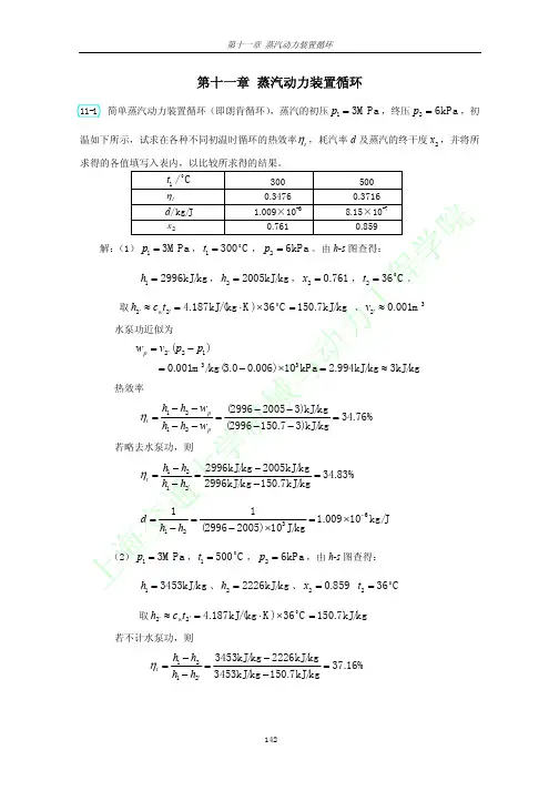
第11章蒸汽动力装置循环11-1朗肯循环中,汽轮机入口参数为:p1=12MPa、t1=540℃。
试计算乏汽压力分别0.005MPa、0.01MPa和0.1MPa时的循环热效率,通过比较计算结果,说明什么问题?解:查水和水蒸汽焓-熵图,汽轮机入口焓为:h1=3455kJ/kg乏汽压力p c为0.005MPa时:乏汽焓h2=2015kJ/kg,温度t s =34℃给水泵入口焓h2´=4.1868t s =4.1868×34=142.351kJ/kg11-3 某再热循环,其新汽参数为p1=12MPa、t1=540℃,再热压力为5MPa,再热后的温度为540℃,乏汽压力为p2=6kPa,设汽机功率为125MW,循环水在凝汽器中的温升为10℃。
不计水泵耗功。
求循环热效率、蒸汽流量和流经凝汽器的循环冷却水流量。
解:据 36001000mnet q w P =,蒸汽流量h t w P q net m /61.27710001621101253600100036003=×××==根据凝汽器中的热平衡:冷却水吸收的热量=乏汽放出的热量 )(32h h q t c q m w p w −=∆循环水流量 ()()h t t c h h q q w p m w /81.13440101868.4912.154218261.27732=×−×=∆−=11-4 水蒸气绝热稳定流经一汽轮机,入口p 1=10MPa 、t 1=510℃,出口p 2=10kPa ,x 2=0.9,如果质量流量为100kg/s ,求:汽轮机的相对内效率及输出功率。
解:查h-s 图:热效率 %36.44583.3663583.20381112=−=−=q q t η 机组功率()()MW 69.2253600583.2038583.36631000500q q P 21m m =−××=−==q q w net11-6 汽轮机理想动力装置,功率为125MW ,其新汽参数为p 1=10MPa 、t 1=500℃,采用一次抽汽回热,抽汽压力为2MPa ,乏汽压力为p 2=10kPa ,不计水泵耗功。
11-1空气压缩致冷装置致冷系数为2.5,致冷量为84600kJ/h ,压缩机吸入空气的压力为0.1MPa ,温度为-10℃,空气进入膨胀机的温度为20℃,试求:压缩机出口压力;致冷剂的质量流量;压缩机的功率;循环的净功率。
解:压缩机出口压力1)12(1/)1(-=-k k p p ε 故:))1/(()11(12-+=k k p p ε=0.325 MPa 2134p p p p = T3=20+273=293K k k p p T T /)1()34(34-==209K 致冷量:)41(2T T c q p -==1.01×(263-209)=54.5kJ/kg 致冷剂的质量流量==2q Q m 0.43kg/s k k p p T T /)1()12(12-==368K 压缩功:w1=c p (T2-T1)=106 kJ/kg压缩功率:P1=mw1=45.6kW膨胀功:w2= c p (T3-T4)=84.8 kJ/kg膨胀功率:P2=mw2=36.5kW循环的净功率:P=P1-P2=9.1 KW11-2空气压缩致冷装置,吸入的空气p1=0.1MPa ,t1=27℃,绝热压缩到p2=0.4MPa ,经冷却后温度降为32℃,试计算:每千克空气的致冷量;致冷机消耗的净功;致冷系数。
解:已知T3=32+273=305Kk k p p T T /)1()12(12-==446K k k p p T T /)1()34(34-==205K 致冷量:)41(2T T c q p -==1.01×(300-205)=96kJ/kg致冷机消耗的净功: W=c p (T2-T1)-c p (T3-T4)=46.5kJ/kg 致冷系数:==wq 2ε 2.06 11-3蒸气压缩致冷循环,采用氟利昂R134a 作为工质,压缩机进口状态为干饱和蒸气,蒸发温度为-20℃,冷凝器出口为饱和液体,冷凝温度为40℃,致冷工质定熵压缩终了时焓值为430kJ/kg ,致冷剂质量流量为100kg/h 。
1-11 A barometer is used to measure the height of a building by recording reading at the bottom and at the top of the building. The height of the building is to be determined. Assumptions The variation of air density with altitude is negligible.Properties The density of air is given to be ρ = 1.18 kg/m 3density of mercury is 13,600 kg/m 3.Analysis building arekPa100.70N/m 1000kPa1m/s kg 1N1m) )(0.755m/s )(9.807kg/m (13,600)(kPa97.36m/s kg 1N1m) )(0.730m/s )(9.807kg/m (13,600)(2223bottombottom 223toptop =⎪⎪⎭⎫⎝⎛⎪⎪⎭⎫⎝⎛⋅===⎪⎪⎭⎫⎝⎛⋅==h g P h g ρP ρTaking an air column between the top and the bottom of the building and writing a force balance per unit base area, we obtainkPa 97.36)(100.70N/m 1000kPa 1m/s kg 1N1))(m/s )(9.807kg/m (1.18)(/2223topbottom air topbottom air -=⎪⎪⎭⎫⎝⎛⎪⎪⎭⎫⎝⎛⋅-=-=h P P gh P P A W ρIt yields h = 288.6 mwhich is also the height of the building.1-21 The air pressure in a duct is measured by an inclined manometer. For a given vertical level difference, the gage pressure in the duct and the length of the differential fluid column are to be determined.Assumptions The manometer fluid is an incompressible substance.Properties The density of the liquid is given to be ρ = 0.81 kg/L = 810 kg/m 3. Analysis The gage pressure in the duct is determined fromPa636=⎪⎪⎭⎫⎝⎛⎪⎪⎭⎫⎝⎛⋅==-=2223atm abs gage N/m 1Pa1m/s kg 1N1m) )(0.08m/s )(9.81kg/m (810ghP P P ρ The length of the differential fluid column is730 mmHgcm 13.9=︒==35sin /)cm 8(sin /θh LDiscussion Note that the length of the differential fluid column is extended considerably by inclining the manometer arm for better readability.2-4 No. This is the case for adiabatic systems only.2-6 A classroom is to be air-conditioned using window air-conditioning units. The cooling load is due to people, lights, and heat transfer through the walls and the windows. The number of 5-kW window air conditioning units required is to be determined.Assumptions There are no heat dissipating equipment (such as computers, TVs, or ranges) in the room. Analysis The total cooling load of the room is determined fromQ Q Q Q cooling lights people heat gain =++whereQ Q Q lights people heat gain 10100W 1kW40360kJ /h 4kW 15,000kJ /h 4.17kW=⨯==⨯=== Substituting,.Q cooling 9.17kW =++=14417Thus the number of air-conditioning units required is units 2−→−=1.83kW/unit 5kW9.172-18 The flow of air through a flow channel is considered. The diameter of the wind channel downstream from the rotor and the power produced by the windmill are to be determined. Analysis The specific volume of the air is/k g m 8409.0k P a100K) K)(293/kg m kP a 287.0(33=⋅⋅==P RT v The diameter of the wind channel downstream from the rotor ism 7.38===−→−=−→−=m/s9m/s10m) 7()4/()4/(21122221212211V V D D V D V D V A V A ππ The mass flow rate through the wind mill iscool·kg/s 7.457/kg)m 4(0.8409m/s)(10m) 7(3211===πvV A mThe power produced is thenkW 4.35=⎪⎭⎫⎝⎛-=-=22222221/s m 1000kJ/kg 12)m/s 9()m/s 10(kg/s)7.457(2V V m W 2-19 The available head, flow rate, and efficiency of a hydroelectric turbine are given. The electric power output is to be determined.Assumptions 1 The flow is steady. 2 Water levels at the reservoir and the discharge site remain constant. 3 Frictional losses in piping are negligible. Properties We take the density of water to beρ = 1000 kg/m 3 = 1 kg/L.Analysis The total mechanical energy the water in a dam possesses is equivalent to the potential energy of water at the free surface of the dam (relative to free surface of discharge water), and it can be converted to work entirely. Therefore, the power potential of water is its potential energy,which is gz per unit mass, and gz m for a given mass flow rate.kJ/kg 177.1/s m 1000kJ/kg 1m ) 120)(m /s (9.81222mech =⎪⎭⎫ ⎝⎛===gz pe e The mass flow rate iskg/s ,000100/s)m 0)(10kg/m 1000(33===V ρmThen the maximum and actual electric power generation becomeMW 7.117kJ/s 1000MW 1kJ/kg) 7kg/s)(1.17 000,100(mech mech max =⎪⎭⎫ ⎝⎛===e mE WMW 94.2===MW) 7.117(80.0max overall electric W W η Discussion Note that the power generation would increase by more than 1 MW for each percentage point improvement in the efficiency of the turbine –generator unit.3-9 A rigid container that is filled with R-134a is heated. The temperature and total enthalpy are to be determined at the initial and final states.Analysis This is a constant volume process. The specific volume is/kg m 0014.0kg10m 014.03321====m Vv vR-134a 300 kPa 10 kgThe initial state is determined to be a mixture, and thus the temperature is the saturation temperature at the given pressure. From Table A-12 by interpolation C 0.61︒==kPa 300 @sat 1T TandkJ/kg52.54)13.198)(009321.0(67.52009321.0/kgm )0007736.0067978.0(/kg m )0007736.00014.0(113311=+=+==--=-=fg f fgf h x h h x v v vThe total enthalpy is thenkJ 545.2===)kJ/kg 52.54)(kg 10(11mh HThe final state is also saturated mixture. Repeating the calculations at this state,C 21.55︒==kPa 600 @sat 2T TkJ/kg64.84)90.180)(01733.0(51.8101733.0/kgm )0008199.0034295.0(/kg m )0008199.00014.0(223322=+=+==--=-=fg f fgf h x h h x v v vkJ 846.4===)kJ/kg 64.84)(kg 10(22mh H3-22 rigid tank contains an ideal gas at a specified state. The final temperature is to be determined for two different processes.Analysis (a ) The first case is a constant volume process. When half of the gas is withdrawn from the tank, the final temperature may be determined from the ideal gas relation as()K 400=⎪⎭⎫ ⎝⎛==K) 600(kP a 300kP a 1002112212T P P m m T (b ) The second case is a constant volume and constant mass process. The ideal gas relation for this case yields kPa 200=⎪⎭⎫ ⎝⎛==kP a) 300(K 600K 4001122P T T P3-32 Complete the following table for H 2 O :P , kPa T , ︒C v , m 3 / kgu , kJ/kg Phase description 200 30 0.001004 125.71 Compressed liquid 270.3130--Insufficient informationv200 400 1.5493 2967.2 Superheated steam 300133.520.5002196.4Saturated mixture, x=0.825500 473.1 0.6858 3084 Superheated steam4-14 Oxygen is heated to experience a specified temperature change. The heat transfer is to be determined for two cases.Assumptions 1 Oxygen is an ideal gas since it is at a high temperature and low pressure relative to its critical point values of 154.8 K and 5.08 MPa. 2 The kinetic and potential energy changes are negligible, 0pe ke ≅∆≅∆. 3 Constant specific heats can be used for oxygen.Properties The specific heats of oxygen at the average temperature of (25+300)/2=162.5︒C=436 K are c p = 0.952 kJ/kg ⋅K and c v = 0.692 kJ/kg ⋅K (Table A-2b ).Analysis We take the oxygen as the system. This is a closed system since no mass crosses the boundaries of the system. The energy balance for a constant-volume process can be expressed as)(12in energiesetc. potential, kinetic, internal,in Change system massand work,heat,by nsfer energy tra Net out in T T mc U Q E E E -=∆=∆=-vThe energy balance during a constant-pressure process (such as in a piston-cylinder device) can be expressed as)(12in out ,in out ,in energiesetc. potential, kinetic, internal,in Change system massand work,heat,by nsfer energy tra Net outin T T mc H Q U W Q UW Q E E E p b b -=∆=∆+=∆=-∆=-since ∆U + W b = ∆H during a constant pressure quasi-equilibrium process. Substituting for both cases, kJ 190.3=-⋅=-==K )25K)(300kJ/kg 692.0(kg) 1()(12const in,T T mc Q v VkJ 261.8=-⋅=-==K )25K)(300kJ/kg 952.0(kg) 1()(12const in,T T mc Q p P4-25 A rigid tank filled with air is connected to a cylinder with zero clearance. The valve is opened, and air is allowed to flow into the cylinder. The temperature is maintained at 30︒C at all times. The amount of heat transfer with the surroundings is to be determined.Assumptions 1 Air is an ideal gas. 2 The kinetic and potential energy changes are negligible,∆∆ke pe ≅≅0. 3 There are no work interactions involved other than the boundary work. Properties The gas constant of air is R = 0.287 kPa.m 3/kg.K (Table A-1).Analysis We take the entire air in the tank and the cylinder to be the system. This is a closed system since no mass crosses the boundary of the system. The energy balance for this closed system can be expressed asoutb,in 12out b,in energiesetc. potential, kinetic,internal,in Change system massand work,heat,by nsfer energy tra Net out in 0)(W Q u u m U W Q E E E ==-=∆=-∆=-since u = u (T ) for ideal gases, and thus u 2 = u 1 when T 1 = T 2 . The initial volume of air is33112212222111m 0.80)m (0.41kP a200kP a 400=⨯⨯==−→−=V V V V T T P P T P T P The pressure at the piston face always remains constant at 200 kPa. Thus the boundary work done during this process iskJ 80m kPa 1kJ 10.4)m kPa)(0.8 (200)( 312221out b,=⎪⎪⎭⎫⎝⎛⋅-=-==⎰V V V P d P W Therefore, the heat transfer is determined from the energy balance to bekJ 80==in out b,Q W4-27 An insulated cylinder is divided into two parts. One side of the cylinder contains N 2 gas and the other side contains He gas at different states. The final equilibrium temperature in the cylinder when thermal equilibrium is established is to be determined for the cases of the piston being fixed and moving freely.Assumptions 1 Both N 2 and He are ideal gases with constant specific heats. 2 The energy stored in the container itself is negligible. 3 The cylinder is well-insulated and thus heat transfer is negligible. Properties The gas constants and the constant volume specific heats are R = 0.2968 kPa.m 3/kg.K is c v = 0.743 kJ/kg·°C for N 2, and R = 2.0769 kPa.m 3/kg.K is c v = 3.1156 kJ/kg·°C for He (Tables A-1 and A-2)Analysis The mass of each gas in the cylinder is()()()()()()()()kg0.808K 298K /kg m kPa 2.0769m 1kPa 500kg 4.77K 353K /kg m kPa 0.2968m 1kPa 50033He111He33N 111N 22=⋅⋅=⎪⎪⎭⎫ ⎝⎛==⋅⋅=⎪⎪⎭⎫ ⎝⎛=RT P m RT P m V VTaking the entire contents of the cylinder as our system, the 1st law relation can be written as()()He12N 12HeN energiesetc. potential, kinetic, internal,in Change system massand work,heat,by nsfer energy tra Net out in )]([)]([0022T T mc T T mc U U U E E E -+-=∆+∆=∆=∆=-v vSubstituting,()()()()()()0C 25C kJ/kg 3.1156kg 0.808C 80C kJ/kg 0.743kg 4.77=︒-︒⋅+︒-⋅f fT TIt givesT f = 57.2︒Cwhere T f is the final equilibrium temperature in the cylinder.The answer would be the same if the piston were not free to move since it would effect only pressure, and not the specific heats.Discussion Using the relation P V = NR u T , it can be shown that the total number of moles in the cylinder is 0.170 + 0.202 = 0.372 kmol, and the final pressure is 510.6 kPa.6-9 An inventor claims to have developed a heat engine. The inventor reports temperature, heat transfer, and work output measurements. The claim is to be evaluated.Analysis The highest thermal efficiency a heat engine operating between two specified temperature limits can have is the Carnot efficiency, which is determined from42%or 42.0K500K 29011C th,max th,=-=-==H L T T ηη The actual thermal efficiency of the heat engine in question is42.9%or 0.429kJ700kJ300net th ===H Q W η which is greater than the maximum possible thermal efficiency. Therefore, this heat engine is a PMM2 and the claim is false .6-11 A heat pump maintains a house at a specified temperature. The rate of heat loss of the house and the power consumption of the heat pump are given. It is to be determined if this heat pump can do the job.Assumptions The heat pump operates steadily.Analysis The power input to a heat pump will be a minimum when the heat pump operates in a reversible manner. The coefficient of performance of a reversible heat pump depends on the temperature limits in the cycle only, and is determined from ()()()14.75K 27322/K 273211/11COP rev HP,=++-=-=H L T TThe required power input to this reversible heat pump is determined from the definition of the coefficient of performance to bekW 2.07=⎪⎪⎭⎫ ⎝⎛==s 3600h 114.75kJ/h 110,000COP HP min in,net,H Q W This heat pump is powerful enough since 5 kW > 2.07 kW.7-8A reversible heat pump with specified reservoir temperatures is considered. The entropy change of two reservoirs is to be calculated and it is to be determined if this heat pump satisfies the increase in entropy principle.Assumptions The heat pump operates steadily. Analysis Since the heat pump is completely reversible, the combination of the coefficient of performance expression, first Law, and thermodynamic temperature scale gives73.26)K 294/()K 283(11/11COP rev HP,=-=-=HL T T The power required to drive this heat pump, according to the coefficient of performance, is thenkW 741.326.73kW 100COP rev HP,in net,===HQ WAccording to the first law, the rate at which heat is removed from the low-temperature energy reservoir iskW 26.96kW 741.3kW 100in net,=-=-=W Q Q H L The rate at which the entropy of the high temperature reservoir changes, according to the definition of the entropy, iskW/K 0.340===∆K294kW 100H HHT Q S and that of the low-temperature reservoir iskW/K 0.340-=-==∆K283kW 26.96L L L T Q S The net rate of entropy change of everything in this system iskW/K 0=-=∆+∆=∆340.0340.0total L H S S Sas it must be since the heat pump is completely reversible.net7-11 Steam is expanded in an isentropic turbine. The work produced is to be determined. Assumptions 1 This is a steady-flow process since there is no change with time. 2 The process is isentropic (i.e., reversible-adiabatic).Analysis There is one inlet and two exits. We take the turbine as the system, which is a control volume since mass crosses the boundary. The energy balance for this steady-flow system can be expressed in the rate form aso u tin energiesetc. potential, kinetic, internal,in change of Rate (steady) 0systemmassand work,heat,by nsfer energy tra net of Rate out in 0E E E E E==∆=-332211out out332211h m h m h m W W h m h m h m --=++=From a mass balance,kg/s 75.4)kg/s 5)(95.0(95.0kg/s 25.0)kg/s 5)(05.0(05.01312======m mm mNoting that the expansion process is isentropic, the enthalpies at three states are determined as follows:6)-A (Table KkJ/kg 6953.7kJ/kg4.2682C 100 kPa 503333 ⋅==⎭⎬⎫︒==s h T P 6)-A (Table kJ/kg 3.3979K kJ/kg 6953.7 MPa 41311=⎭⎬⎫⋅===h s s P 6)-A (Table kJ/kg 1.3309K kJ/kg 6953.7 kPa 7002322=⎭⎬⎫⋅===h s s P Substituting,kW6328=--=--=kJ/kg) .4kg/s)(2682 75.4(kJ/kg) .1kg/s)(3309 25.0(kJ/kg) .3kg/s)(3979 5(332211outh m h m h m W7-13 The entropy change relations of an ideal gas simplify to∆s = c p ln(T 2/T 1) for a constant pressure processand ∆s = c v ln(T 2/T 1) for a constant volume process.Noting that c p > c v , the entropy change will be larger for a constant pressure process.7-22 Air is compressed in a piston-cylinder device. It is to be determined if this process is possible.Assumptions 1 Changes in the kinetic and potential energies are negligible. 4 Air is an ideal gas with constant specific heats. 3 The compression process is reversible.Properties The properties of air at room temperature are R = 0.287 kPa ⋅m 3/kg ⋅K, c p = 1.005 kJ/kg ⋅K (Table A-2a).Analysis We take the contents of the cylinder as the system. This is a closed system since no mass enters or leaves. The energy balance for this stationary closed system can be expressed asin,out 12out in ,12out in ,12out in ,energiesetc. potential, kinetic, internal,in Change system massand work,heat,by nsfer energy tra Net out in )(since 0)( )(b b p b b W Q T T Q W T T mc Q W u u m U Q W E E E ===--=--=∆=-∆=-The work input for this isothermal, reversible process iskJ/kg 8.897kP a100kP a 250K)ln K)(300kJ/kg 287.0(ln12in =⋅==P P RT w That is,kJ/kg 8.897in out ==w qThe entropy change of air during this isothermal process isK kJ/kg 0.2630kP a100kP a250K)ln kJ/kg 287.0(ln ln ln121212air ⋅-=⋅-=-=-=∆P P R P P R T T c s p The entropy change of the reservoir isK kJ/kg 0.2630K300kJ/kg 89.78R R ⋅===∆R T q s Note that the sign of heat transfer is taken with respect to the reservoir. The total entropy change (i.e., entropy generation) is the sum of the entropy changes of air and the reservoir:K kJ/kg 0⋅=+-=∆+∆=∆2630.02630.0R air total s s sNot only this process is possible but also completely reversible.8-1 The four processes of an air-standard cycle are described. The cycle is to be shown on P-v and T-s diagrams, and the maximum temperature in the cycle and the thermal efficiency are to be determined.Assumptions 1 The air-standard assumptions are applicable. 2 Kinetic and potential energy changes are negligible. 3 Air is an ideal gas with constant specific heats.Properties The properties of air at room temperature are c p = 1.005 kJ/kg.K, c v = 0.718 kJ/kg·K, and k = 1.4 (Table A-2).Analysis (b ) From the ideal gas isentropic relations and energy balance,()()K 579.2k P a 100k P a1000K 3000.4/1.4/11212=⎪⎪⎭⎫ ⎝⎛=⎪⎪⎭⎫ ⎝⎛=-kk P P T THeatv()()()K3360==−→−-⋅=-=-=3max 32323in 579.2K kJ/kg 1.005kJ/kg 2800T T T T T c h h q p(c )()K 336K 3360kP a1000kP a1003344444333===−→−=T P P T T P T P v v ()()()()()()()()21.0%=-=-==-⋅+-⋅=-+-=-+-=+=k J /k g2800k J /k g 221211k J /k g2212K 300336K k J /k g 1.005K 3363360K k J /k g 0.718in out th14431443out 41,out 34,out q q T T c T T c h h u u q q q p ηvDiscussion The assumption of constant specific heats at room temperature is not realistic in this case the temperature changes involved are too large.8-5 An ideal Otto cycle with air as the working fluid has a compression ratio of 9.5. The highest pressure and temperature in the cycle, the amount of heat transferred, the thermal efficiency, and the mean effective pressure are to be determined.Assumptions 1 The air-standard assumptions are applicable. 2 Kinetic and potential energy changes are negligible. 3 Air is an ideal gas with constant specific heats.Properties The properties of air at room temperature are c p = 1.005 kJ/kg·K, c v = 0.718 kJ/kg·K, R = 0.287 kJ/kg·K, and k = 1.4 (Table A-2). Analysis (a ) Process 1-2: isentropic compression.()()()()kP a 2338kP a 100K 308K 757.99.5K757.99.5K 3081122121112220.412112=⎪⎪⎭⎫⎝⎛==−→−===⎪⎪⎭⎫ ⎝⎛=-P T T P T P T P T T k v v v v vvProcess 3-4: isentropic expansion.()()K 1969==⎪⎪⎭⎫ ⎝⎛=-0.4134439.5K 800k T T vvProcess 2-3: v = constant heat addition.()kPa 6072=⎪⎪⎭⎫⎝⎛==−→−=kPa 2338K 757.9K 19692233222333P T T P T P T P v v (b ) ()()()()kg 10788.6K 308K /kg m kPa 0.287m 0.0006kPa 100433111-⨯=⋅⋅==RT P m V vs()()()()()kJ0.590=-⋅⨯=-=-=-K 757.91969K kJ/kg 0.718kg 106.78842323in T T mc u u m Q v(c) Process 4-1: v = constant heat rejection.()()()()kJ0.2 40K 308800K kJ/kg 0.718kg 106.788)(41414out =-⋅⨯-=-=-=-T T mc u u m Q v kJ 0.350240.0590.0out in net =-=-=Q Q W59.4%===kJ0.590kJ0.350inout net,th Q W η(d ) ()()kPa 652=⎪⎪⎭⎫⎝⎛⋅-=-=-===kJm kPa 1/9.51m 0.0006kJ0.350)/11(MEP 331outnet,21outnet,max 2min r W W rV V V V V V8-7 An ideal diesel cycle has a a cutoff ratio of 1.2. The power produced is to be determined.Assumptions 1 The air-standard assumptions are applicable. 2 Kinetic and potential energy changes are negligible. 3 Air is an ideal gas with constant specific heats.Properties The properties of air at room temperature are c p = 1.005 kJ/kg·K, c v = 0.718 kJ/kg·K, R = 0.287 kJ/kg·K, and k = 1.4 (Table A-2a). Analysis The specific volume of the air at the start of the compression is/kg m 8701.0kPa95K)288)(K /kg m kPa 287.0(33111=⋅⋅==P RT vThe total air mass taken by all 8 cylinders when they are charged is kg 008665.0/kgm 8701.0m)/4 12.0(m) 10.0()8(4/3212cyl 1cyl===∆=ππv v VS B N N mThe rate at which air is processed by the engine is determined fromkg/s 1155.0rev/cycle2rev/s) 1600/60kg/cycle)( (0.008665rev ===N nm msince there are two revolutions per cycle in a four-stroke engine. The compression ratio is2005.01==r At the end of the compression, the air temperature is()K 6.95420K) 288(14.1112===--k r T ToutApplication of the first law and work integral to the constant pressure heat addition giveskJ/kg 1325K )6.9542273)(K kJ/kg 005.1()(23in =-⋅=-=T T c q pwhile the thermal efficiency is6867.0)12.1(4.112.12011)1(1114.111.41th =---=---=--c k c k r k r r ηThe power produced by this engine is thenkW105.1====kJ/kg) 67)(1325kg/s)(0.68 (0.1155in th net netq m w m W η8-12 An aircraft engine operates as a simple ideal Brayton cycle with air as the working fluid. The pressure ratio and the rate of heat input are given. The net power and the thermal efficiency are to be determined.Assumptions 1 Steady operating conditions exist. 2 The air-standard assumptions are applicable. 3 Kinetic and potential energy changes are negligible. 4 Air is an ideal gas with constant specific heats. Properties The properties of air at room temperature are c p = 1.005 kJ/kg·K and k = 1.4 (Table A-2a).Analysis For the isentropic compression process,K .1527K)(10) 273(0.4/1.4/)1(12===-kk p r T TThe heat addition iskJ/kg 500kg/s1kW 500in in===m Q qApplying the first law to the heat addition process,K 1025KkJ/kg 1.005kJ/kg500K 1.527)(in 2323in =⋅+=+=-=p p c q T T T T c q The temperature at the exit of the turbine isK 9.530101K) 1025(10.4/1.4/)1(34=⎪⎭⎫⎝⎛=⎪⎪⎭⎫⎝⎛=-kk p r T TApplying the first law to the adiabatic turbine and the compressor produceskJ/kg 6.496K )9.5301025)(K kJ/kg 1.005()(43T =-⋅=-=T T c w pkJ/kg 4.255K )2731.527)(K kJ/kg 1.005()(12C =-⋅=-=T T c w pThe net power produced by the engine is thenkW 241.2=-=-=kJ/kg )4.2556kg/s)(496. 1()(C T netw w m W Finally the thermal efficiency is0.482===kW 500kW241.2innet thQ W η。
第一章基本概念与定义1.答:不一定。
稳定流动开口系统内质量也可以保持恒定2.答:这种说法是不对的。
工质在越过边界时,其热力学能也越过了边界。
但热力学能不是热量,只要系统和外界没有热量地交换就是绝热系。
3.答:只有在没有外界影响的条件下,工质的状态不随时间变化,这种状态称之为平衡状态。
稳定状态只要其工质的状态不随时间变化,就称之为稳定状态,不考虑是否在外界的影响下,这是他们的本质区别。
平衡状态并非稳定状态之必要条件。
物系内部各处的性质均匀一致的状态为均匀状态。
平衡状态不一定为均匀状态,均匀并非系统处于平衡状态之必要条件。
4.答:压力表的读数可能会改变,根据压力仪表所处的环境压力的改变而改变。
当地大气压不一定是环境大气压。
环境大气压是指压力仪表所处的环境的压力。
5.答:温度计随物体的冷热程度不同有显著的变化。
6.答:任何一种经验温标不能作为度量温度的标准。
由于经验温标依赖于测温物质的性质,当选用不同测温物质的温度计、采用不同的物理量作为温度的标志来测量温度时,除选定为基准点的温度,其他温度的测定值可能有微小的差异。
7.答:系统内部各部分之间的传热和位移或系统与外界之间的热量的交换与功的交换都是促使系统状态变化的原因。
8.答:(1)第一种情况如图1-1(a),不作功(2)第二种情况如图1-1(b),作功(3)第一种情况为不可逆过程不可以在p-v图上表示出来,第二种情况为可逆过程可以在p-v图上表示出来。
9.答:经历一个不可逆过程后系统可以恢复为原来状态。
系统和外界整个系统不能恢复原来状态。
10.答:系统经历一可逆正向循环及其逆向可逆循环后,系统恢复到原来状态,外界没有变化;若存在不可逆因素,系统恢复到原状态,外界产生变化。
11.答:不一定。
主要看输出功的主要作用是什么,排斥大气功是否有用。
第二章 热力学第一定律1.答:将隔板抽去,根据热力学第一定律w u q +∆=其中0,0==w q 所以容器中空气的热力学能不变。
第一章热力学基本概念 英文习题1. Expressing temperature rise in different unitsDuring a heating process, the temperature of a system rises by 10°C. Express this rise in temperature in K, °F and R.2. Absolute pressure of a vacuum chamberA vacuum gage connected to a chamber reads 5.8 psi at locationwhere the atmosphere pressure is 14.5 psi. Determine the absolutepressure in the chamber.3. Measuring pressure with a manometerA manometer is used to measure the pressure in a tank. The fluidused has a specific gravity of 0.85, and the manometer columnheight is 55 cm, as shown in Fig.1-1. If the local atmosphericpressure is 96 kPa, determine the absolute pressure within the tank. 4. Measuring pressure with a multi-fluid manometerThe water in a tank is pressurized by air, and the pressure ismeasured by a multi-fluid manometer as shown in Fig. 1-2. Thetank is located on a mountain at an altitude of 1400 m wherethe atmospheric pressure is 85.6 kPa. Determine the airpressure in the tank if hi=0.1 m, h2=0.2 m, and h3=0.35 m.Take the densities of water, oil, and mercury to be 1000 kg/m 3,850 kg/m 3, and 13 600 kg/m 3 respectively.5. Effect of piston weight on pressure in acylinderThe piston of a vertical piston-cylinder device containing a gas has a mass of 60 kg and a cross-sectional area of 0.04 m 2, as shown in Fig.1-3. The local atmosphere pressure is 0.97 bar, and the gravitational acceleration is 9.81 m/s 2. (a) Determine the pressure inside the cylinder, (b) If some heat is transferred to the gas and its volume is doubled, do you expect the pressure inside the cylinder to change?|6. Burning off lunch caloriesA 90-kg man had two hamburgers, a regular serving of French fries, and a 200-ml Coke for lunch. FIGURE 1-1FIGURE 1-3Determine how long it will take for him to burn the lunch calories off (a) by watching TV and (b) by fast swimming. What would your answers be for a 45-kg man?7. Burning of a candle in an insulated roomA candle is burning in a well-insulated room. Taking the room (the airplus the candle) as the system, determine (a) if there is any heattransfer during this burning process and (b) if there is any change inthe internal energy of the system.8. Boundary work during a constant-volume processA rigid tank contains air at 500 kPa and 150°C. As a result of heattransfer to the surroundings, the temperature and pressure inside thetank drop to 65°C and 400 kPa, respectively. Determine the boundarywork done during theprocess.9. Isothermal compression of an ideal gasA piston-cylinder device initially contains 0.4 m 3 of air at 100 kPa and 80°C. The air is nowcompressed to 0.1 m 3 in such a way that the temperature inside the cylinder remains constant. Determine the work done during this process.10. Heat transfer from a personConsider a person standing in a breezy room at 20°C. Determinethe total rate of heat transfer from this person if the exposedsurface area and the average outer surface temperature of theperson are 1.6 m 2 and 29°C, respectively, and the convectionheat transfer coefficient is 6 W/m 2.°C (Fig.1-7) 工程热力学与传热学 第一章基本概念习题 中文习题P.kPap 2=AIR T 2V] = 0.4 m 3 Pl TOO kPa FIGI 7o=8O°C = const.FIGURE 1-4FIGURE 1-61. 平衡状态与稳定状态有何区别?热力学中为什么要引入平衡状态的概念?2. 表压力或真空度能否作为状态参数进行热力计算?若工质的压力不变,问测量其压力的压力表或真空计的读数是否可能变化?3. 真空表指示数值越大,被测对象的实际压力愈大还是愈小?4. 准平衡过程与可逆过程有何区别?5. 不可逆过程是无法回到初态的过程,这种说法是否正确?6. 没有盛满开水的热水瓶,其瓶塞有时被自动顶开,有时被自动吸紧,这是什么原理?7. 用U形管压力表测定工质的压力时,压力表液柱直径的大小对读数有无影响?8. 某容器被一刚性壁分为两部分,在容器不同部位装有3个压力表,如图示,压力表B的读数为1.75bar,压力表A的读数为1.10bar»如果大气压力计读数为0.97bar,试确定压力表C的读数及两部分容器内气体的绝对压力。
53习题提示与答案第十一章 水蒸气及蒸汽动力循环11-1 试根据水蒸气的h -s 图,求出下述已知条件下各状态的其他状态参数p 、v 、t 、h 、s 及x (或过热蒸汽的过热度D =t -t s )。
已知: (1) p =0.5 MPa 、t =500 ℃; (2) p =0.3 MPa 、h =2 550 kJ/kg ; (3) t =180 ℃、s =6.0 kJ/(kg ·K); (4) p =0.01 MPa 、x =0.90; (5) t =400 ℃、D =150 ℃。
提示:水蒸气h -s 图上,两个独立的状态参数可确定一个状态;饱和区内,p 、T 两个参数直接相关。
答案:h =3 500 kJ/kg ,s =8.08 kJ/(kg·k),x =1,=v 0.72 m 3/kg, =D 448 ℃;(1)s =6.54 kJ/(kg·k),x =0.921,t =134 ℃,57.0=v m 3/kg ;(2)h =2 534 kJ/kg, x =0.865,=v 0.168 m 3/kg ;(3)h =2 534 kJ/kg ,s =7.4 kJ/(kg·k),t =46 ℃;(4)h =3 200 kJ/kg ,s =6.68 kJ/(kg·k),x =1,p =3.97 MPa 。
11-2 根据水蒸气表,说明下述已知条件下各状态的其他状态参数t 、v 、h 及s 。
已知: (1) p =0.3 MPa 、t =300 ℃; (2) p =0.5 MPa 、t =155 ℃;(3) p =0.3 MPa 、x =0.92。
提示:参照习题11-1的提示;湿饱和蒸汽的状态与其干度有关。
答案:(1)kg m 16081.03=v ,kg kJ 2.4299=h ,K kJ 8540.6⋅=s ;(2)kg m 525093001.03=v ,kg kJ 525.656=h ,K kg kJ 5886.1⋅=s ;(3)v /kg m 48557.03=;h =2 552.372 kJ/kg ;s =6.567 3 kJ/( kg·k )读万卷书 行万里路11-3 某锅炉每小时生产10 t 水蒸气,蒸汽的压力为1 MPa 、温度为350 ℃,锅炉给水的压力为1 MPa 、温度为40 ℃。
11-13An ideal vapor-compression refrigeration cycle with refrigerant-134a as the working fluid is considered. The rate of heat removal from the refrigerated space, the power input to the compressor, the rate of heat rejection to the environment, and the COP are to be determined.Assumptions 1 Steady operating conditions exist. 2 Kinetic and potential energy changes are negligible.Analysis (a ) In an ideal vapor-compression refrigeration cycle, the compression process is isentropic, the refrigerant enters the compressor as a saturated vapor at the evaporator pressure, and leaves the condenser as saturated liquid at the condenser pressure. From the refrigerant tables (Tables A-12 and A-13),()()throttlingkJ/kg 82.88kJ/kg82.88liquid sat.MP a 7.0C 95.34kJ/kg 50.273MP a 7.0K kJ/kg 94779.0kJ/kg97.236 vapor sat.kP a 12034MPa 7.0 @ 3322122kPa 120 @ 1kPa 120 @ 11=≅==⎭⎬⎫=︒==⎭⎬⎫==⋅====⎭⎬⎫=h h h h P T h s s P s s h h P f g gThen the rate of heat removal from therefrigerated space and the power input to the compressor are determined fromand()()()()()()kW 1.83kW 7.41=-=-==-=-=kJ/kg 236.97273.50kg/s 0.05kJ/kg 82.8897.236kg/s 0.0512in41h h m W h h m Q L(b ) The rate of heat rejection to the environment is determined fromkW 9.23=+=+=83.141.7inW Q Q L H (c ) The COP of the refrigerator is determined from its definition,4.06===kW 1.83kW7.41COP inR W Q L11-15An ideal vapor-compression refrigeration cycle with refrigerant-134a as the working fluid is considered. The throttling valve in the cycle is replaced by an isentropic turbine. The percentage increase in the COP and in the rate of heat removal from the refrigerated space due to this replacement are to be determined.sAssumptions 1 Steady operating conditions exist. 2 Kinetic and potential energy changes are negligible.Analysis If the throttling valve in the previous problem is replaced by an isentropic turbine, we would have s 4s = s 3 = s f @ 0.7 MPa = 0.33230 kJ/kg·K and the enthalpy at the turbine exit would be()()()kJ/kg58.8248.2142802.049.222802.085503.009275.033230.0kPa120 @44kPa120 @34=+=+==-=⎪⎪⎭⎫⎝⎛-=fgs f s fg fs h x h h s s s xThen,()()()kW 7.72kJ/kg 82.58236.97kg/s 0.0541=-=-=s Lh h m Q and23.4kW 1.83kW 7.72COP inR ===W Q LThen the percentage increase in Qand COP becomes4.2%4.2%=-=∆==-=∆=06.406.423.4COP COP COP in Increase 41.741.772.7in Increase R R R L L L Q Q Q11-23A vapor-compression refrigeration cycle with refrigerant-134a as the working fluid isconsidered. The amount of cooling, the work input, and the COP are to bedetermined. Also, the same parameters are to be determined if the cycle operated on the ideal vapor-compression refrigeration cycle between the same temperature limits. Assumptions 1 Steady operating conditions exist. 2 Kinetic and potential energy changes are negligible. Analysis (a) The expansion process through the expansionsvalve is isenthalpic: h 4 = h 3. Then,kJ/kg 159.3=-=-=19.24349.40241h h q L kJ/kg 8.21019.24300.45432=-=-=h h q H kJ/kg 51.51=-=-=49.40200.45412in h h w3.093===kJ/kg51.51kJ/kg3.159COP in w q L (c) Ideal vapor-compression refrigeration cycle solution:kJ/kg 149.2=-=-=80.24904.39941h h q LkJ/kg 190.980.24971.44032=-=-=h h q H kJ/kg 41.67=-=-=04.39971.44012in h h w3.582===kJ/kg67.41kJ/kg 2.149COP in w q LDiscussion In the ideal operation, the refrigeration load decreases by 6.3% and the work input by 19.1% while the COP increases by 15.8%.11-75A regenerative gas refrigeration cycle using air as the working fluid is considered. The effectiveness of the regenerator, the rate of heat removal from the refrigerated space, the COP of the cycle, and the refrigeration load and the COP if this system operated on the simple gas refrigeration cycle are to be determined.Assumptions 1 Steady operating conditions exist. 2 Kinetic and potential energy changes are negligible. 3 Air is an ideal gas with constant specific heats.Properties The properties of air at room temperature are c p = 1.005 kJ/kg·K and k = 1.4 (Table A-2).Analysis (a ) From the isentropic relations, ()()()K 4.4325K 2.2734.1/4.0k/1k 1212==⎪⎪⎭⎫ ⎝⎛=-PP T T sK5.4722.2732.2734.43280.02212121212=−→−--=--=--=T T T T TT h h h h s s C ηThe temperature at state 4 can be determined by solvingsthe following two equations simultaneously:()4.1/4.04k/1k 454551⎪⎭⎫ ⎝⎛=⎪⎪⎭⎫ ⎝⎛=-T PP T T sss T T T T h h h h 54454542.19385.0--=→--=ηUsing EES, we obtain T 4 = 281.3 K.An energy balance on the regenerator may be written asor,()()K3.2463.2812.3082.273431661436143=+-=+-=-=-−→−-=-T T T T T T T T T T c m T T c m p pThe effectiveness of the regenerator is0.434=--=--=--=3.2462.3083.2812.30863436343regen T T T T h h h h ε (b ) The refrigeration load iskW 21.36=-=-=K )2.19346.3kJ/kg.K)(2 5kg/s)(1.00 4.0()(56T T c m Q p L(c ) The turbine and compressor powers and the COP of the cycle are kW 13.80K )2.27372.5kJ/kg.K)(4 5kg/s)(1.00 4.0()(12in C,=-=-=T T c mW p kW 43.35kJ/kg )2.19381.3kJ/kg.K)(2 5kg/s)(1.00 4.0()(54out T,=-=-=T T c m W p0.478=-=-==43.3513.8036.21COP outT,in C,innet,W W Q WQ LL0︒C35︒-80︒(d ) The simple gas refrigeration cycle analysis is as follows:()()K 6.19451K 2.30814.1/4.0k/1k 34=⎪⎭⎫⎝⎛=⎪⎭⎫ ⎝⎛=-r T T sK6.2116.1942.3082.30885.0444343=−→−--=−→−--=T T T T T T s T η kW24.74=-=-=kJ/kg )6.21173.2kJ/kg.K)(2 5kg/s)(1.00 4.0()(41T T c m Q p L[]kW32.41kJ/kg )6.211(308.2)2.273(472.5kJ/kg.K)5kg/s)(1.00 4.0()()(4312in net,=---=---=T T c m T T c mW p p 0.599===32.4174.24COP innet,WQ Ls35︒。