PXIe资料汇总整理
- 格式:docx
- 大小:428.74 KB
- 文档页数:7

PXIe资料汇总一、物理结构PXIe国际规范的3U机箱母座物理接口中,PXI 联盟命名Peripheral Modules 为XJ3 和XJ4接口,相应公座称为XP3、XP4。
生产制造厂商中德国ENRI较多被使用,型号对应情况:XJ3 -> ENRI 973028 ;XJ4 -> ENRI 214443;XP3 -> ENRI 973027;XP4 -> ENRI 224057。
PXIe母座底面图PXIe母座侧面图二、接口定义2.1 概述根据PXI联盟定义3U 机箱中Peripheral Modules 的XJ3和XJ4硬件接口定义如下所示:2.2 XP3/XJ31PETp0~7/1PETn0~7/1PERp0~7/1PERn0~7数据差分线收发各八组[1],p56,CompactPCI Express中PET和PER命名规则与PCI Express相反,按外设板连接器为准,PET信号(如A5/B5)方向是从外设到系统,PER(如C5/D5)方向是从系统到外设。
电容耦合发生在发射侧[3],p64。
RefClk±100M差分时钟,该信号由backplane提供作为module的PCIe工作时钟。
该信号不是星型信号,各个slot间RefClk±相位不一致。
信号性质为LVPECL,可在外设侧电容耦合转换为其他电平[3],p80。
PERST#硬复位。
方向从slot到module,拉高表示PXI电源和参考时钟均已稳定[3],p99。
PRSNT#热插拔,低电平有效。
module接地处理。
PWREN#方向从系统到外设,一般用于开启外设版的主电源芯片,低电平有效。
此为短引脚,支持热插拔的外设可将该脚电阻上拉,在板卡插入过程的最后开启主电源[3],p107。
MPWRGD方向从外设到系统,表示外设电源已稳定,高电平有效。
支持热插拔的板卡,应将这个脚用10K电阻下拉到地,并接电源芯片PG脚[3],p108。

高性能测试测量与控制平台—PXI系统应用摘要:PXI中引入了PXIExpress技术,显著提高了总线带宽。
PXI将PCIExpress集成到PXI标准中,可以满足更...PXI中引入了PXI Express技术,显著提高了总线带宽。
PXI将PCI Express集成到PXI标准中,可以满足更多的应用需求。
PCI Express技术可以集成到背板中,同时维持与现有系统的后向兼容性。
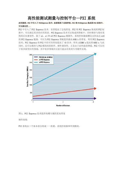
除了x1、x4和x8 PCI Express链路外,系统控制器插槽还支持高达x16的PCI Express链路,可以为PXI Express背板提供最高6GB/s的带宽。
利用PCI Express 技术,PXI Express将PXI中的可用带宽提高了45倍多,即从132MB/s提高到6GB/s;与此同时,还可以维持与PXI模块间的软件、硬件兼容性。
正是由于此性能的增强,PXI可以用于很多新型应用领域,其中很多领域在以前只能由昂贵的专用硬件实现。
图1. PCI Express技术提供每槽专属的更高带宽硬件架构PXI系统由三个基本部分组成——机箱、系统控制器和外围模块。
图2. 标准的8槽PXI机箱中,包括一个嵌入式系统控制器和七个外围模块PXI机箱PXI机箱为系统提供了坚固的模块化封装,通常为4槽、6槽、8槽、14槽或18槽的3U或6U机箱。
U(rack unit)是一种测量单位,用来描述安装在19或23英寸(指宽度)机架上的设备的高度。
1U等于44.45mm(1.75英寸)。
装在机架上的设备的尺寸大小通常用U来描述。
专用机箱还可在交流电源和直流电源中选择,以及是否集成信号调理功能。
很多PXI Express 机箱中都可以容纳PXI和PXI Express外围设备,而有些具有混合插槽的机箱(如NI PXIe-1075),还可以容纳PXI Express外围设备或者兼容混合插槽的PXI设备。
利用这些机箱可以配置多种PXI系统从而满足应用需求。
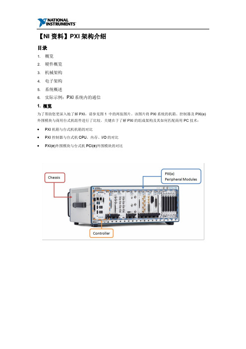
【NI资料】PXI架构介绍目录1. 概览2. 硬件概览3. 机械架构4. 电子架构5. 系统概述6. 实际示例:PXI系统内的通信1. 概览为了帮助您更深入地了解PXI,请参见图1 中的两张图片。
该图片将PXI系统的机箱、控制器及PXI(e)外围模块与商用台式机组件进行了比较。
关键在于了解PXI的组成架构及其如何匹配商用PC技术:∙PXI机箱与台式机机箱的对比∙PXI控制器与台式机CPU、内存、I/O的对比∙PXI(e)外围模块与台式机PCI(e)外围模块的对比图 1. PXI系统与商用台式机的对比PXI(面向仪器系统的PCI扩展) 是一个基于PC的成熟平台,适用于测量和自动化系统。
它提供了电源、冷却和通信总线来支持同一机箱内的多个仪器模块。
PXI采用基于PC的商用PCI总线技术,但同时结合了坚固的CompactPCI模块化封装以及重要的定时和同步功能。
外围部件互连专业组(PCI-SIG)发布了PCI的进化版——PCI Express标准,显著提高了系统带宽。
负责管理PXI的PXI系统联盟(PXISA)采用了最新一代的商用PC总线技术,实现了PXI到PXI Express的演变。
PXI Express保持了PXI功能,以确保系统的向后兼容性,除了具有标准的PXI功能外,它还提供了更高的带宽、电源、冷却、定时和同步功能。
PXI和PXI Express拥有如此丰富的功能,看起来似乎非常复杂,但是,这些技术的核心是相同的:主流PC通信总线。
PXI和PXI Express机箱为当代工程师的测量和自动化系统提供了一个应用广泛的成熟架构。
由于PXI是由PXISA管理的开放式规范,任何厂商都可开发PXI产品。
为了更好地解释底层PXI系统细节,本文重点介绍了PXISA制定的PXI规范,以及这些规范如何在NI PXI硬件中得到体现。
2. 硬件概览The PXISA 硬件规范规定了与机械、电子和软件架构相关的所有要求。

GETTING STARTED GUIDEPXIe-5764PXI FlexRIO DigitizerNote Before you begin, install and configure your chassis and controller.This document explains how to install, configure, test, and use the PXIe-5764. You can program the PXIe-5764 with the following software options.•FlexRIO Support driver software•NI LabVIEW Instrument Design Libraries for FlexRIO (instrument design libraries) Note Adapter modules are not installable or interchangeable on PXIe-5764devices.Caution This icon denotes a caution, which advises you to consult documentationwhere this symbol is marked.ContentsSafety Guidelines (2)Electromagnetic Compatibility Guidelines (2)FlexRIO Documentation and Resources (2)Verifying the System Requirements (3)Unpacking the Kit (3)PXIe-5764 Kit Contents (4)Preparing the Environment (4)Installing the Application Software and Driver (4)Installing the PXIe-5764 (5)PXIe-5764 Front Panel (6)Configuring the PXIe-5764 in MAX (8)FlexRIO Examples (9)Accessing FlexRIO Examples (9)Block Diagram (9)Component-Level Intellectual Property (CLIP) (11)PXIe-5764 CLIP (12)Making a Measurement (12)Making a Measurement with LabVIEW (12)Troubleshooting (12)What Should I Do if the PXIe-5764 Doesn't Appear in MAX? (12)What Should I Do if the PXIe-5764 Fails the Self-Test? (13)Where to Go Next...................................................................................................................13Worldwide Support and Services.. (13)Safety GuidelinesCaution You can impair the protection provided by the PXIe-5764 if you use it ina manner not described in this document.Electromagnetic Compatibility GuidelinesThis product was tested and complies with the regulatory requirements and limits forelectromagnetic compatibility (EMC) stated in the product specifications. These requirements and limits provide reasonable protection against harmful interference when the product is operated in the intended operational electromagnetic environment.This product is intended for use in industrial locations. However, harmful interference may occur in some installations, when the product is connected to a peripheral device or test object,or if the product is used in residential or commercial areas. To minimize interference with radio and television reception and prevent unacceptable performance degradation, install and use this product in strict accordance with the instructions in the product documentation.Furthermore, any changes or modifications to the product not expressly approved by National Instruments could void your authority to operate it under your local regulatory rules.FlexRIO Documentation and Resources2 | | PXIe-5764 Getting Started GuideTable 1. FlexRIO Documentation and Resources (Continued)Verifying the System RequirementsTo use the PXIe-5764, your system must meet certain requirements. For more information about minimum system requirements, recommended system, and supported application development environments (ADEs), refer to the readme, which is available on the software media or online at /updates .Unpacking the KitNotice To prevent electrostatic discharge (ESD) from damaging the device, groundyourself using a grounding strap or by holding a grounded object, such as your computer chassis.1.Touch the antistatic package to a metal part of the computer chassis.2.Remove the device from the package and inspect the device for loose components or any other sign of damage.Notice Never touch the exposed pins of connectors.Note Do not install a device if it appears damaged in any way.3.Unpack any other items and documentation from the kit.PXIe-5764 Getting Started Guide | © National Instruments | 3Store the device in the antistatic package when the device is not in use.PXIe-5764 Kit ContentsThe following items are included in the device kit:•The PXIe-5764•The FlexRIO Support driver software media•Documentation:–Maintain Forced-Air Cooling Note to Users–PXIe-5764 Getting Started Guide (this document)Preparing the EnvironmentEnsure the environment in which you are using the PXIe-5764 meets the following specifications.Operating environmentAmbient temperature range0 °C to 45 °C (Tested in accordance withIEC-60068-2-1 and IEC-60068-2-2. MeetsMIL-PRF-28800F Class 3 low temperaturelimit and MIL-PRF-28800F Class 4 hightemperature limit.)Relative humidity range10% to 90%, noncondensing (Tested inaccordance with IEC 60068-2-56.) Maximum altitude2,000 m (800 mbar) (at 25 °C ambienttemperature)Pollution Degree2Indoor use only.Note For complete specifications, refer to the specifications document for yourdevice at /manuals.Installing the Application Software and Driver Before installing your hardware, you must install the application software and instrument driver. Visit NI FlexRIO Driver Supported Versions for FlexRIO Adapters and Modules to determine which minimum software versions you need for your device. Install the software in the following order:1.Install LabVIEW.4| | PXIe-5764 Getting Started GuideRefer to the LabVIEW Installation Guide for installation instructions for LabVIEW and system requirements for the LabVIEW software. Refer to the LabVIEW Upgrade Notes for additional information about upgrading to the most recent version of LabVIEW for Windows. Documentation for LabVIEW is available at /manuals and by selecting Start»All Programs»National Instruments»LabVIEW»LabVIEW Manuals.2.Install the LabVIEW FPGA Module.Refer to the LabVIEW FPGA Module Release and Upgrade Notes for installationinstructions and information about getting started with the LabVIEW FPGA Module.Documentation for the LabVIEW FPGA Module is available at /manuals and by selecting Start»All Programs»National Instruments»LabVIEW»LabVIEWManuals.3.Install FlexRIO Support.Refer to the FlexRIO Readme on the FlexRIO installation media for system requirements and installation instructions for FlexRIO Support. Documentation for FlexRIO Support is available at /manuals and by selecting Start»All Programs»NationalInstruments»NI FlexRIO.Installing the PXIe-5764Notice To prevent damage to the PXIe-5764 caused by ESD or contamination,handle the module using the edges or the metal bracket.1.Ensure the AC power source is connected to the chassis before installing the module.The AC power cord grounds the chassis and protects it from electrical damage while you install the module.2.Power off the chassis.3.Inspect the slot pins on the chassis backplane for any bends or damage prior toinstallation. Do not install a module if the backplane is damaged.4.Remove the black plastic covers from all the captive screws on the module front panel.5.Identify a supported slot in the chassis. The following figure shows the symbols thatindicate the slot types.Figure 1. Chassis Compatibility Symbols1.PXI Express System Controller Slot2.PXI Peripheral Slot3.PXI Express Hybrid Peripheral Slot4.PXI Express System Timing Slot5.PXI Express Peripheral SlotPXIe-5764 modules can be placed in PXI Express peripheral slots, PXI Express hybrid peripheral slots, or PXI Express system timing slots.PXIe-5764 Getting Started Guide| © National Instruments| 56.Touch any metal part of the chassis to discharge static electricity.7.Ensure that the ejector handle is in the downward (unlatched) position.8.Place the module edges into the module guides at the top and bottom of the chassis. Slide the module into the slot until it is fully inserted.Figure 2. Module Installation1.Chassis2.Hardware Module3.Ejector Handle in Downward (Unlatched) Positiontch the module in place by pulling up on the ejector handle.10.Secure the module front panel to the chassis using the front-panel mounting screws.Note Tightening the top and bottom mounting screws increases mechanicalstability and also electrically connects the front panel to the chassis, which can improve the signal quality and electromagnetic performance.11.Cover all empty slots using EMC filler panels or fill using slot blockers to maximizecooling air flow, depending on your application.12.Power on the chassis.PXIe-5764 Front PanelThe following figure shows the PXIe-5764 front panel.6 | | PXIe-5764 Getting Started GuideFigure 3. PXIe-5764 Front PanelThe following table describes the signal connections for the PXIe-5764.PXIe-5764 Getting Started Guide| © National Instruments| 7The following table lists the available pins on the DIO connector.Notice The maximum input signal levels are valid only when the module ispowered on. To avoid permanent damage to the PXIe-5764, do not apply a signal tothe device when the module is powered down.Notice Connections that exceed any of the maximum ratings of any connector onthe PXIe-5764 can damage the device and the chassis. NI is not liable for anydamage resulting from such connections.Configuring the PXIe-5764 in MAXUse Measurement & Automation Explorer (MAX) to configure your NI hardware. MAX informs other programs about which NI hardware products are in the system and how they are configured. MAX is automatically installed with FlexRIO Support.unch MAX.2.In the configuration tree, expand Devices and Interfaces to see the list of installed NIhardware.Installed modules appear under the name of their associated chassis.1MGTs are available only on devices with KU040 and KU060 FPGAs.8| | PXIe-5764 Getting Started Guide3.Expand your Chassis tree item.MAX lists all modules installed in the chassis. Your default names may vary.Note If you do not see your module listed, press <F5> to refresh the list ofinstalled modules. If the module is still not listed, power off the system, ensurethe module is correctly installed, and restart.4.Record the identifier MAX assigns to the hardware. Use this identifier whenprogramming the PXIe-5764.5.Self-test the hardware by selecting the item in the configuration tree and clicking Self-Test in the MAX toolbar.The MAX self-test performs a basic verification of hardware resources.FlexRIO ExamplesFlexRIO includes several example applications for LabVIEW. These examples serve as interactive tools, programming models, and as building blocks in your own applications. Accessing FlexRIO ExamplesFlexRIO examples are available in LabVIEW's NI Example Finder. Complete the following steps to access the examples by task.1.In LabVIEW, click Help»Find Examples.2.In the NI Example Finder window that appears, click Hardware Input and Output»FlexRIO.The examples are sorted by task. Click on an example and refer to the Informationwindow for a description of the example. Refer the Requirements window for a list of hardware devices that can run the example.You can also click the Search tab to search all installed examples by keyword. Forexample, search for FlexRIO to locate all FlexRIO examples.Examples also are available online that demonstrate FlexRIO basics, such as using DRAM, acquiring data from adapter modules, and performing high throughput streaming. Refer to /examples for these examples and for more information.Block DiagramThe following figure shows a block diagram of the carrier portion of the PXIe-5764 (KU035 FPGA version).PXIe-5764 Getting Started Guide| © National Instruments| 9Figure 4. Carrier Block Diagram (KU035)The following figure shows a block diagram of the carrier portion of the PXIe-5764 (KU040 and KU060 FPGA versions).Figure 5. Carrier Block Diagram (KU040 and KU060)The following figure shows a block diagram of the I/O portion of the PXIe-5764.10| | PXIe-5764 Getting Started GuideFigure 6. PXIe-5764 Block DiagramNote Only one analog input path type is populated. Refer to and the devicespecifications for more details.Component-Level Intellectual Property (CLIP) The LabVIEW FPGA Module includes component-level intellectual property (CLIP) for HDL IP integration. FlexRIO devices support two types of CLIP: user-defined and socketed.•User-defined CLIP allows you to insert HDL IP into an FPGA target, enabling VHDL code to communicate directly with an FPGA VI.•Socketed CLIP provides the same IP integration of the user-defined CLIP, but it also allows the CLIP to communicate directly with circuitry external to the FPGA. Adapter module socketed CLIP allows your IP to communicate directly with both the FPGA VI and the external adapter module connector interface.The PXIe-5764 ships with socketed CLIP items that add module I/O to the LabVIEW project.PXIe-5764 Getting Started Guide| © National Instruments| 11PXIe-5764 CLIPThe PXIe-5764 CLIP provides access to four AC- or DC-coupled analog input channels.In the LabVIEW FPGA Module, 16-bit analog input data is accessed using an I16 data type. The DIO signals are grouped into two ports of four signals each and are accessed using a U8 data type and a Boolean write enable signal.Making a MeasurementMaking a Measurement with LabVIEWunch LabVIEW.2.Select Help»Find Example.3.Open the example VI that you want to use by selecting Hardware Input and Output»FlexRIO.4.Follow any setup, configuration, and execution instructions in the VI.TroubleshootingIf an issue persists after you complete a troubleshooting procedure, contact NI technical support or visit /support.What Should I Do if the PXIe-5764 Doesn't Appear in MAX?1.In the MAX configuration tree, expand Devices and Interfaces.2.Expand the Chassis tree to see the list of installed hardware, and press <F5> to refreshthe list.3.If the module is still not listed, power off the system, ensure that all hardware is correctlyinstalled, and restart the system.4.Navigate to the Device Manager.Operating System DescriptionWindows 7Select Start»Control Panel»Device Manager.5.Verify the PXIe-5764 appears in the Device Manager.a)Under an NI entry, confirm that a PXIe-5764 entry appears.Note If you are using a PC with a device for PXI remote control system,under System Devices, also confirm that no error conditions appear for thePCI-to-PCI Bridge.b)If error conditions appear, reinstall FlexRIO Support and the PXIe-5764.12| | PXIe-5764 Getting Started GuideWhat Should I Do if the PXIe-5764 Fails the Self-Test?1.Restart the system.unch MAX, and perform the self-test again.3.Power off the chassis.4.Reinstall the failed module in a different slot.5.Power on the chassis.6.Perform the self-test again.Where to Go NextRefer to the following figure for information about other product tasks and associated resources for those tasks.Worldwide Support and ServicesThe NI website is your complete resource for technical support. At /support, you have access to everything from troubleshooting and application development self-help resources to email and phone assistance from NI Application Engineers.PXIe-5764 Getting Started Guide| © National Instruments| 13Visit /services for NI Factory Installation Services, repairs, extended warranty, and other services.Visit /register to register your NI product. Product registration facilitates technical support and ensures that you receive important information updates from NI.A Declaration of Conformity (DoC) is our claim of compliance with the Council of the European Communities using the manufacturer’s declaration of conformity. This system affords the user protection for electromagnetic compatibility (EMC) and product safety. You can obtain the DoC for your product by visiting /certification. If your product supports calibration, you can obtain the calibration certificate for your product at /calibration.NI corporate headquarters is located at 11500 North Mopac Expressway, Austin, Texas, 78759-3504. NI also has offices located around the world. For telephone support in the United States, create your service request at /support or dial 1 866 ASK MYNI (275 6964). For telephone support outside the United States, visit the Worldwide Offices section of / niglobal to access the branch office websites, which provide up-to-date contact information, support phone numbers, email addresses, and current events.Information is subject to change without notice. Refer to the NI T rademarks and Logo Guidelines at /trademarks for information on NI trademarks. Other product and company names mentioned herein are trademarks or trade names of their respective companies. For patents covering NI products/technology, refer to the appropriate location: Help»Patents in your software, the patents.txt file on your media, or the National Instruments Patent Notice at /patents. Y ou can find information about end-user license agreements (EULAs) and third-party legal notices in the readme file for your NI product. Refer to the Export Compliance Information at /legal/export-compliance for the NI global trade compliance policy and how to obtain relevant HTS codes, ECCNs, and other import/export data. NI MAKES NO EXPRESS OR IMPLIED WARRANTIES AS TO THE ACCURACY OF THE INFORMATION CONT AINED HEREIN AND SHALL NOT BE LIABLE FOR ANY ERRORS. U.S. Government Customers: The data contained in this manual was developed at private expense and is subject to the applicable limited rights and restricted data rights as set forth in FAR 52.227-14, DFAR 252.227-7014, and DFAR 252.227-7015.© 2018 National Instruments. All rights reserved.376460B-01July 11, 2018。

是德科技PXI 和 AXIe 仪器、软件、参考解决方案及服务是德科技模块化解决方案无与伦比的性能。
加速测量洞察。
开启测量新视野是德科技传承 75 年创新史,始终致力于为用户开启全新的测量视野。
秉承这一理念一路走来,我们创造了业界领先的测试测量设备,总有适合的产品能够满足您的需求:全尺寸的台式仪器、小型台式仪器、手持式仪表或模块化仪器。
我们的目标是提供全面的全球测试解决方案 - 硬件、软件、全球支持和应用专业技术,为您的团队提供所需的知识和技能,使其保持行业领先优势。
在模块化仪器领域,我们的硬件创新主要集中在两个特定的领域:PXI 和 AXIe 。
我们将无与伦比的测量性能和始终一致的测量技术融入 PXI 和 AXIe 系列射频、微波和高速数字仪器中。
为了帮助您更快开始构建测试系统,我们记录了许多针对特定应用领域(从功率放大器测试到卫星信号监测)的参考解决方案供您借鉴。
软件是所有测试系统都不可或缺的组成部分 ― 是德科技软件将我们渊博的专业技术集于一身,供您下载使用。
我们为您的团队提供卓越的工具,帮助您加速将数据转化为信息,进而转化为可以指导实践的洞察力。
我们还提供软件面板控制和基本的实用程序,从而使我们的模块化产品开箱后几分钟内即可投入使用,确保您快速开始首次测量。
是德科技拥有业界非常庞大的应用工程师团队 ― 他们遍布全球各地,而且在射频、微波和数字等领域积累了极其丰富的技术经验,在业界长期保持领先优势。
是德科技的全球三年标准保修是我们对卓越产品质量的承诺。
我们的多厂商一站式校准和正常运行时间服务,确保您的仪器具有持续的精度、性能和可用性。
我们能以快达四小时的响应时间,创建定制的服务计划。
我们在全球拥有超过 50 个服务地点的服务网络和移动校准团队,可以提供更大的便利和灵活性,保持您的产品和测试系统以保证的技术指标运行。
是德科技的模块化解决方案通过提供无与伦比的 PXI 和 AXIe 性能,帮助您应对射频、微波和数字领域最苛刻的技术挑战。
PXI Express 概述PXI Express Hardware Specification哈尔滨工业大学•PXI平台的发展历史主要内容•PXI Express的新特性•PXI Express的兼容性•PXI Express的产品及应用•参考文献•PCI总线概述•PXI总线与PCI总线的关系PXI平台的发展历史•PCIe总线概述•PXIe与PCIe的关系PCI总线概述•PCI---P eripheral C omponent I nterconnect,周边器件互连•1991,Intel-PCI SIG•1992,PCI局部总线规范v1.0•33MHz/32bit---133MB/s•66MHz/64bit---533MB/s•PCI总线的局限性: 频率和效率(反射波信号驱动器)总线上设备越多,信号传播、加倍、建立所需的时间越长。
电气负载数量随着总线频率的上升而下降,带宽受限PCI总线的效率约为50%-60%,影响效率的因素有:总线仲裁时间、总线周期之间的闲态时间等PXI总线与PCI总线的关系•PICMG---PCI Industrial ComputerManufacturer’s Group•Compact PCI:欧卡,电气、逻辑和软件与PCI完全兼容性;坚固耐用的PCI版本,用于工业和嵌入式应用•PXI---PCI extensions for instrument,NI•PXISA---PXI System Alliance,1997仪器信号定时、触发等测试信号PCIe总线概述•对于带宽的需求(如:高清晰度的无压缩视频和音频)•2002,Intel,“第三代I/O接口标准”•串行、点对点、差分、独享带宽•带宽大幅度提升(理论上能达到16GB/s)•软件与PCI兼容PXIe 与PCIe 的关系PCI ---> PCI Express仪器信号Compact PCI ---> Compact PCI ExpressPXI ---> PXI Express•专业术语•PCIe的电气特性PXI Express的新特性•从PCIe获得的大幅提升的带宽•超高精度的同步和定时功能•机械结构的相应变化专业术语•链路(Link):从物理上将两个PCI Express设备点对点连接到一起的一个PCI Express互连•通路(Lane):一条链路在单个方向上所包含的信号对•8/10b编码:将串行数据的位发送时钟嵌入到串行位流中,使8位字符扩展为10位后再发送,开销增加25%。
Keysight M924xAInfiniiVision PXIe 模块化示波器全功能示波器,带宽高达1 GHz,适用于模块化环境技术资料是德科技将模块化示波器带入全新层面配备了示波器 SFP(软件前面板),将InfiniiVision 台式示波器技术融入到PXI架构之中。
–M9241A PXIe 模块化示波器 - 200 MHz 带宽–M9242A PXIe 模块化示波器 - 500 MHz 带宽–M9243A PXIe 模块化示波器 - 1 GHz 带宽模块化的架构,台式示波器的实力InfiniiVision M924xA 系列重新定义了模块化示波器。
它能为您提供更多的信号细节,最大限度地保护您的投资,并且充分利用了是德科技在过去数十年中积累的示波器专业技术。
性能–200 MHz、500 MHz 和1 GHz 带宽,适应各种不同的测量应用–高级触发功能支持复杂信号的捕获和分析–视觉触发(区域触摸和模板)有助于轻松、快速地触发和捕获感兴趣的信号或异常–串行协议分析和触发–自动快速傅立叶变换(FFT)和波形运算扩展分析,满足您的需求–分段存储器可以连续捕获多达 1000 个事件,无需抓一个事件转存到电脑上再抓第二个事件测量能力–支持是德科技 InfiniiVision 系列兼容的所有探头–高精度电流探头–电源轨探头–高压探头–30 多种自动测量,让分析变得简单集多款仪器于一身–示波器支持高达 1 GHz 带宽和 5 GSa/s 采样率–3 位 DVM(数字电压表),共享示波器的探头–8 位计数器,支持累加器和频率计数器测量–协议分析仪支持 I²C、UART、CAN、LIN、CXPI 等协议–硬件加速的FFT频谱测量分析–20 MHz 任意波形发生器卓越的分析能力与台式示波器不差分毫常见的模块化仪器多是在数字化仪硬件基础上配一套软件,该软件一般会极力模仿示波器的测试和调试功能。
这样的仪器设计本身带来的局限性常常被忽视,比如,其波形捕获率往往无法和台式示波器相提并论,测试效率低;也无法提供诸如波形平均功能,不提供高级波形触发等功能。
PXIe资料汇总
一、物理结构
PXIe国际规范的3U机箱母座物理接口中,PXI 联盟命名Peripheral Modules 为XJ3 和XJ4接口,相应公座称为XP3、XP4。
生产制造厂商中德国ENRI较多被使用,型号对应情况:XJ3 -> ENRI 973028 ;XJ4 -> ENRI 214443;XP3 -> ENRI 973027;XP4 -> ENRI 224057。
PXIe母座底面图PXIe母座侧面图
二、接口定义
2.1 概述
根据PXI联盟定义3U 机箱中Peripheral Modules 的XJ3和XJ4硬件接口定义如下所示:
2.2 XP3/XJ3
1PETp0~7/1PETn0~7/1PERp0~7/1PERn0~7
数据差分线收发各八组[1],p56,CompactPCI Express中PET和PER命名规则与PCI Express相反,按外设板连接器为准,PET信号(如A5/B5)方向是从外设到系统,PER(如C5/D5)方向是从系统到外设。
电容耦合发生在发射侧[3],p64。
RefClk±
100M差分时钟,该信号由backplane提供作为module的PCIe工作时钟。
该信号不是星型信号,各个slot间RefClk±相位不一致。
信号性质为LVPECL,可在外设侧电容耦合转换为其他电平[3],p80。
PERST#
硬复位。
方向从slot到module,拉高表示PXI电源和参考时钟均已稳定[3],p99。
PRSNT#
热插拔,低电平有效。
module接地处理。
PWREN#
方向从系统到外设,一般用于开启外设版的主电源芯片,低电平有效。
此为短引脚,支持热插拔的外设可将该脚电阻上拉,在板卡插入过程的最后开启主电源[3],p107。
MPWRGD
方向从外设到系统,表示外设电源已稳定,高电平有效。
支持热插拔的板卡,应将这个脚用10K电阻下拉到地,并接电源芯片PG脚[3],p108。
SMBCLK
SMBus用,I2C时钟线。
在系统板上为上拉状态[3],p86-p87。
外设板可以不用[3],p85;[4],p79。
和热插拔是独立功能,具体问题见[3],p108。
SMBDAT
SMBus用,I2C数据线。
在系统板上为上拉状态[3],p86-p87。
外设板可以不用[3],p85;[4],p79。
和热插拔是独立功能,具体问题见[3],p108。
PXIe_CLK100±
3.3V LVPECL 100M差分时钟,该信号由backplane提供作为module的可选工作时钟,传输线差分阻抗100R并端接[4],p66。
该信号为星型信号,各个slot间PXIe_CLK100±相位一致。
用法是接入FPGA,但并不作为FPGA的主时钟,而是执行某一项需要与其他slot之间同时工作需要同步采样时的基准时钟,可以在此时钟上进行分/倍频。
一块板卡各个CPU主时钟均独立,为石英晶振。
PXIe_SYNC100±
星型同步信号,3.3V LVPECL,外设板传输线差分阻抗100R并端接[4],p66。
此信
号是(周期不规定的)10ns正脉冲,它为高电平时出现的PXIe_CLK100的上升沿,表示下一个PXIe_CLK100上升沿是与PXI_CLK10上升沿对齐[4],p67。
利用此信号和PXIe_CLK100配合,可以产生一个与PXI_CLK10有确定相位关系的分频时钟[4],p73。
PXIe_DSTARA/PXIe_DSTARB/PXIe_DSTARC:
为三组可选星型差分时钟信号。
振源来源于时钟模块板卡(可配),时钟板卡在槽中的位置是固定的,如果带有时钟卡,槽位在中间位。
通过backplane传输到其他slot,当PXIe_CLK100提供不了用户需求时使用。
2.3 XP4/XJ4
Power
各slot分别配有12V、5V、3.3V开关电源,电流信息如下图所示:
PXI_TRIG[7:0]
各slot上的8组TRIG信号线是分别互通,与主机控制器无关。
作用是一块卡通过slot发出一组或多组TRIG,其他slot上可捕获时间,识别TRIG。
PXI_CLK10
作用与上述PXIe_CLK100类似,但为3.3V 单端时钟10M。
PXI_CLK10和PXIe_CLK100同相[4],p67。
PXI_STAR
星型触发信号,各slot互通,由主机控制器发出。
与PXI_TRIG[7:0]有所区别。
PXI_LBL6/LBR6:
链状信号,各module之间可以与相邻左右板卡通信[4],p65。
该线可以承受较高电压,也可以用来传递模拟信号[5],p22。
GA[4:0]
slot信息位,总共支持32个。
用于外设板识别自己在哪个槽上,信号由系统发往slot,高阻态为1,地为0[3],p103。
SYSEN#:
该信号用于识别系统槽,在背板系统槽上接地、其他槽悬空。
外设板不会用到[3],p103。
WAKE#:
用于外设板唤醒系统板。
如果外设不支持WAKE,该脚悬空处理。
WAKE与热插拔是独立功能[3],p108。
ALERT#:
I2C选择信号SMBus用,在系统板上为上拉状态[3],p86-p87。
外设板可以不用[3],p85;
[4],p79。
和热插拔是独立功能,具体问题见[3],p108。
ATNLED
系统输出至各个slot,可驱动module上LED[3],p107。
电压3.3V。
ATNSW#:
“attention switch”,外设module接IO控制,系统背板上拉状态。
用于软处理热插拔。
不支持热插拔的外设板,该引脚应悬空;支持热插拔但没有设置IO口控制,直接高电平处理[3],p107。
2.4 热插拔顺序:
子板插入,PWREN#最后连接;
子板PWREN#被拉低,此信号热插拔控制器或稳定器开启;
子板电源稳定,处理器开始接管子板逻辑;
子板拉高MPWRGD,表示配置完毕。
2.5 PCIe
PCIe总线包括了T able 4-9 XP3/XJ3 Connector中的淡黄色部分(RefClk±、1PETp0~7、1PETn0~7、1PERp0~7、1PERn0~7)、PRSNT#信号及PERST#。
三、驱动及软件
PCIe驱动包由XILINX提供,含驱动源码、测试源码和驱动安装程序,一般情况下不对驱动源码作修改。
编译测试源码需要VS平台(VS2015版本以上)+WDK(1703以上)编译器,win10操作系统。
由于PCIe协议本身较为复杂(详见PCIe总线规范),XILINX为方便用户开发了PCIe IP硬核,官方文档为PG195,如此不需要去关心PCIe本身,只需要熟悉XILINX 硬核使用即行,相对而言要比看PCIe容易的多。
参考文献
[1] PCI Express Card Electromechanical Specification Revision 1.1
[2] PEX8614 Product Brief
[3] CompactPCI Express Specification ,Draft R1.0 RC1
[4] PXI Express Hardware Specification Rev.1.0
[5] PXI Hardware Specification Rev.2.2。