SMITH3012高压液体涡轮流量计
- 格式:pdf
- 大小:373.21 KB
- 文档页数:6
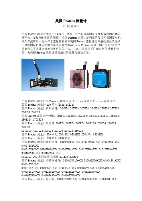
美国Proteus流量计广州南创房工美国Proteus流量计成立于1978年,开发、生产和市场的坚固性和敏感的液体流量开关,仪表和传感器的范围。
美国Proteus流量计是领先的亏损帽探测器和机器人焊接应用中的冷却水流量控制器和美国Proteus流量计的泄漏检测系统提供了最终的保护任务关键设备的灾难性泄漏。
美国Proteus流量计的产品在50多个国家设立了国外办事处及售后服务中心,并在中国设立了广州南创传感器事业部,为美国Proteus流量计提供最佳的服务与解决方案。
美国Proteus流量计有Proteus流量开关 Proteus流量计Proteus流量仪表美国Proteus流量计200系列(load cells)美国Proteus流量计黄铜机身:201B24 205B24 203B24 204B24 250B24 255B24 260B24 270B24美国Proteus流量计不锈钢: 201SS24 205SS24 203SS24 204SS24 250SS24 255SS24 260SS24 270SS24美国Proteus流量计聚乙烯 201P24 205P24 203P24 204PL24 250P24 260P24 270P24Celcon: 201C24 205C24 203C24 204L24 250C24美国Proteus流量计500系列/0504SA2 0504SN2 0504SA4 0504SN4美国Proteus流量计800系列4000系列美国Proteus流量计黄铜机身:04004BN013-XXX 04004BN06-XXX 04004BN1-XXX 04004BN2-XXX04004BN4-XXX 04006BN9-XXX 04008BN14-XXX 04012BN16-XXX 04012BN40-XXX 04016BN40-XXX 04016BN60-XXXProteus 200系列流量传感器 201B24 205B24美国Proteus流量计不锈钢机身:04004SN013-XXX 04004SN06-XXX 04004SN1-XXX 04004SN2-XXX04004SA2-XXX 04004SN4-XXX 04004SA4-XXX 04006SN9-XXX 04008SA10-XXX 04008SN14-XXX 04012SN16-XXX 04012SA16-XXX 04012SN40-XXX04016SN40-XXX 04016SA40-XXX 04016SN40-XXX美国Proteus流量计聚乙烯:04004PN012-XXX 04004PN06-XXX 04004PN1-XXX04004PN2-XXXProteus FF-P流量传感器 FF-P50-1AMAX-PF04004PN4-XXX 04006PN4-XXX 04006PN10-XXX 04008PN14-XXX04012PN19-XXX 04016PN50-XXX美国Proteus流量计6000系列美国Proteus流量计黄铜:06004BN06 06004BN1 06004BN2 06004BN4 06006BN9 06008BN14 06012BA1606012BN40 06016BN40 06016BN60美国Proteus流量计不锈钢:06004SN06 06004SN1 06004SN2 06006SA2 06004SN4 06004SA4 06006SN906008SA10 06008SN14 06012SA16 06012SA16 06012SN40 06016SN40 06016SA40 06016SN60美国Proteus流量计聚乙烯:06004PN06 06004PN1 06004PN2 06004PN4 06006PN10 06008PN1406012PN19 06016PN50美国Proteus流量计8000系列美国Proteus流量计黄铜:08004BND13/08004BN03/08004BN06/08004BN1/08004BN2/08004BN408008BN14/08012BN16/08012BN40/08016BN40/08016BN60美国Proteus流量计不锈钢:/08004SND13/08004SN03/08004SN06/08004SN1/08004SA2/08004SN208006SA2/08004SN4/08006SA4/08006SN9/08008SA10/08008SN14/08012SN16 08012SN40/08016SN40/08006SA40/08016SN60美国Proteus流量计聚乙烯:08004PND13/08004PN06/08004PN1/08004PN2/08004PN4/08006PN1408008PN14/08012PN19/08016PN50美国Proteus流量计叶轮式FF-PFF-P100-1-A1000-PF/FF-P50-9-A1000-PF/FF-P100S-1-B1000-PF/FF-P150-1-B1 000-PFFF-P200-1-A1000-P1/FF-P300-1-A1000-P2/FF-P400-1-BMAX-Z美国Proteus流量计超声波流量计美国Proteus流量计USF100A系列:/USF100A-G05EP-1/USF100A-G10EP-1/USF100A-G15EP-1USF100A-G20EP-1/USF100A-G05EP-9/USF100A-G10EP-9/USF100A-G15EP-9USF100A-G20EP-9/USF200S系列USF200S-G08-1-A300/USF200S-G08-1-ZMAX USF200S-G10-1-AMAX/USF200S-G10-1-ZMAX/USF200S-G08-9-AMAXUSF200S-G08-9-ZMAX/USF200S-G10-9-AMAX/USF200S-G10-9-ZMAX美国Proteus流量计USF300C系列:USF300C-G15-1-A20/USF300C-G15-2-AMAX/USF300C-G15-1-BMAXUSF300C-G20-2-BMAX/USF300C-G20-2-ZMAX美国Proteus流量计技术参数以《OIML60号国际建议》92年版为基础,最新具体变化可查看《JJG669—12 Proteus industries inc广州南创传感事业部检定规程》。
全国流量计各规格型号价格行情大全全国各个地区的流量计价格行情数据(2018.07)来源:一呼百应平台(互联网+制造服务平台)概述:一呼百应是专注于解决制造业企业产品生产环节,为企业提供在线备选供应商、价格指数、采购趋势、上下游匹配撮合、在线交易与供应链金融等服务的B2B平台。
标签:流量计,流量计价格,流量计价格行情,流量计行情走势,流量计规格型号,流量计报价参考源:一呼百应:获“2016德勤-广州高科技高成长20强”荣誉称号一呼百应:获得2018 IEBE(广州)颁布的年度“值得信赖的电商互联网平台服务机构”一呼百应线上交易管理系统获评“广东省高新技术产品”,批准文号:粤高企协(2017)29号一呼百应作为“互联网+制造”服务平台获得“广东省创新型企业”称号。
材料名规格/型号单位品牌省份城市厂家报价生产厂家涡轮流量传感器厂家DN4DN6DN10/XRLWGY-CL适用DN4DN6DN10台鑫瑞思创北京市北京1310.00 北京鑫瑞思创科技有限公司上海墨玄机油加注器OG12003 1/2"硬管/软管/OG12003Transport上海市上海电议上海墨玄机电设备有限公司山东流量计-/TDS-100H - 山东潍坊电议潍坊金水华禹信息科技有限公司欧控机电电磁流量计-/- 台Siemens/西门子广东广州5700.00欧控(广州)智能科技应用有限公司面板流量计电议/电议只清泽同达北京市北京200.00 北京清泽同达环保设备有限公司MKT25-1T前田检流器代理187********/MKT25-1T件前田江苏南京22.00 南京士彩机电设备有限公司流量计-/- 安徽天康安徽滁州电议安徽天康(集团)股份有限公司智能蒸汽流量计/JYLLB 台精英江苏苏州3200.00 昆山精英泵阀有限公司罗斯蒙特1000-20 00流量计/1700/2700/1500/2500Rosemount/罗斯蒙特湖北武汉电议德科蒙武汉公司孔板流量计-/- 件- 山东济南 1.00 济南华控仪表有限公司JMTT流量计多种/JMTT 台弢博上海市上海400.00 上海弢博水处理技术有限公司泊头市仪表总厂涡街流量传感器简介河北沧州电议河北宏业永盛汽车加热器股份有限公司流量计7ME6920 -1AA /7ME6920-1AA10-1AA0西门子上海市上海电议上海泽滔自动化有限公司循环水自来水、壁挂炉流量传感器50mm长,G1/2外牙入水/SEN-HZ21FH个SAIER/赛盛尔广东佛山15.00佛山市顺德区赛盛尔电子科技有限公司连恬气体流量计-/001双环热工江苏泰州电议江苏连恬气体设备有限公司玻璃转子流量计120mm/VA1034 台DWYER 天津市天津0 天津泽益诚科技有限公司厂家直销消防专用流量开关流量计DN50-300/DN50-300台流量开关福建泉州370.00 南安市白沙消防器材有限公司电磁流量计法兰连接10W50-U 两行显示,按键操作/10W50-UAGA1AA0A4AA件E+H/恩德斯豪斯福建厦门 1.00 厦门沐英自动化科技有限公司德尔塔巴流量计/德尔塔巴流量计霍尼尔河北石家庄电议河北霍尼尔科技发展有限公司LMF防腐湿式气体流量计国标/LMF-1/-2 台广诚山东烟台1450.00 烟台广诚商贸有限公司超声波流量计SM-TUFP150/SM-TUFP150台晟铭河南南阳 1.00 南阳晟铭流量仪表有限公司涡街流量计/ZVS上海正迈上海市上海电议上海正迈自动化科技有限公司涡街流量计厂家/ZPLUG 件中普江苏淮安1700.00 江苏中普自动化仪表有限公司蒸汽专用V锥流量计/DN50良恩一表北京市北京电议北京良恩一表科技有限公司蒸汽流量计品牌河北宏业永泰LFX/LFX 台宏业河北沧州2300.00河北宏业永泰流体机械股份有限公司销售部阿牛巴流量计/根据客户要求定制嘉航冠科湖北武汉电议湖北嘉航冠科工控技术有限公司TDS-1000H手持式超声波流TDS-1000H/TDS-1000H套祥和时代科电仪器山东济宁3600.00 济宁祥和时代检测仪器有限公司供应磁电式智能流量计磁电式智能流量计/zjk件明德科技湖北荆州 1.00 荆州市明德科技有限公司新款超声波流量计/DYU-F 其他辽宁丹东电议辽宁东仪自控技术股份有限公司GSL-I超声波明渠流量计台福建福州 1.00 福建蓝水环保科技有限公司永视水流指示器DN10-DN50/SG-YL11件永视阀门浙江温州1000.00 温州永视阀门有限公司电力设备流量计9.0.55/9.0.55 个GICAR 广东深圳780.00 深圳市亚得电器有限公司E+H电磁流量计/Promag 10W 台E+H/恩德斯豪斯河南南阳 1.00 南阳爆团防爆电气科技有限公司WXZJ-DC20A系列电磁流量/WXZJ-DC20A系列台泽钜江苏无锡1500.00 无锡泽钜环保科技有限公司E+H流量计10W 电磁流量计/10 件E+H/恩德斯豪斯广东深圳11111111.00深圳市信沃成自动化技术有限公司高粘度糖浆测量流量计/RZ容积式流量计台negele 广东深圳 1.00 深圳市坤博自动化设备有限公司手持式超声波流量计超声波流量计15-6000/AKTTUF-2000H件爱克特江苏淮安2100.00 江苏爱克特仪表有限公司电磁流量计/YG 甬港上海市上海电议上海铭万智能仪表有限公司BOPPREU THER流20/OR1-SS1SS-G15-L-O1-A1个德国BOPP江苏南京100.00 南京金倍得科技发展有限公司量计REUTHER流量计工业G6-G65煤气计量表/G6-G65 台克罗姆广东佛山2000.00 佛山市燃气设备有限公司电池供电电磁流量计/QTLD青天仪表河南开封电议开封青天伟业流量仪表有限公司ELETTA流量计S25-FA80 /S25-FA80 件ELETTA!@!-516364!@!516364!@!516364上海市上海 1.00 上海昭益机电设备有限公司科隆/克罗尼金属转子流量计DK3标准/DK37 台科隆辽宁葫芦岛5000.00 葫芦岛龙腾自动化工程有限公司涡街流量计dn100/LUGB-2310台海宏达山东青岛999.00 青岛海宏达仪表设备有限公司罗斯蒙特8732EM 流量计/8732EM 件Rosemount/罗斯蒙特湖北武汉99.00德科蒙过程控制(武汉)有限公司日本FLOW CELL流量计FL NFLT-R型(ねじ込み接続)10A~100A/FLT-H型NFVT-LTSFLY-H型DIG-件FLOWCELL江苏南京 1.00 南京高辉机电设备有限公司气体腰轮流量计./. 泊曼森天津市天津电议天津市泊曼森科技发展有限公司E+H 65F热式质量流量计标准规格/65FE+H/恩德斯豪斯湖北武汉电议德科蒙过程控制(武汉)有限公司保定万用表/111 台青仪河北保定11111111.00北京张一元茶庄保定店广州涡轮流量计广西涡轮流DC-LWGY/DC-LWGY台迪川仪器仪表广东广州1100.00广州迪川仪器仪表有限公司市场部量计流量计价格行情大全补充说明:一呼百应平台完整版的流量计价格全国各地区加起来数据占用版面过大,因受限于百度文库文件上传大小、篇幅限制以及价格时效性原因,仅仅只上传前面的一部分。
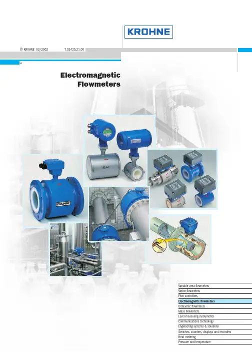
©KROHNE 03/20027.02425.21.00GRElectromagneticFlowmetersVariable area flowmetersVortex flowmetersFlow controllersElectromagnetic flowmetersUltrasonic flowmetersMass flowmetersLevel measuring instrumentsCommunications technologyEngineering systems & solutionsSwitches,counters,displays and recordersHeat meteringPressure and temperatureApplicationKROHNE electromagnetic flowmeters are to be found in many industrial sectors and applications.Just a small selection:G Chemical industry G Water and wastewaterGHydraulic transport,liquid products with up to 50% solids content G Paper and woodpulp production G Pharmaceutical G Food and beveragesG Filling and dispensing processes G Highly abrasive slurriesG High-pressure industrial processes GPartially filled pipelinesand many,many other applications in other industriesFIT and FORGET !All electromagnetic flowmeters are delivered ready for operation.Install the flowmeter in the pipeline,make the electrical connection,that's it.Always one step ahead with KROHNEThis highly accurate measurement technology is available with integrally or remote mounted converter,some with measuring errors of less than 0.2% of the measured value.The primary head is installed in the pipeline,while the signal converter for signal processing is remote mounted in a field housing or 19" plug-in unit.In the integral system,the signal converter is mounted in a housing with high protection category directly on the primary head.With meter sizes of DN2.5 - 3000 / 1/10" - 120",measurements can be carried out from 2l/h to 300 000m3/hand more.Most of the devices are approved for use in hazardous locations.Various materials are available for the measuring tube,liner and electrodes of the flowmeters for most applications. Electromagnetic flowmetersProduction and calibrationAll electromagnetic flowmeters from KROHNE meet the requirements of CE directives and EMC guidelines.Fabrication and production shops are certified to ISO 9001.At KROHNE,all electromagnetic flowmeters are calibrated by direct comparison of volumes,the most accurate calibration method of all.The KROHNE calibration rigs are the world's biggest and most accurate,and are accredited to EN17 025.Measurement uncertainty is less than 0.013% of themeasured value for meter sizes up to DN 3000 / 120" and above.7Electromagnetic flowmeters >0.05 µS /c m >5 µS /c m >20 µS /c m >50 µS /c mD N 2.5,4,6 1/10”,1/6”,1/4”D N 10 3/8”D N 32 11/2”Signal converterDatenblätterF l a n g e c o n n e c t i o n s F l a n g e l e s s ‘s a n d w i c h ’d e s i g n C h e m i c a l s W a t e r a n d s e w a g e P a r t i a l l y f i l l e d p i p e s P h a r m a c e u t i c a l s ,s a n i t a r y B a t c h i n g (1-10s )V e r y a b r a s i v e s l u r r i e s H i g h p r e s s u r e 2- o r 2 x 2-w i r e s y s t e mG e n e r a l p u r p o s e S a n i t a r y c o n n e c t i o n s H A R T ®/R S 485 (s t a n d a r d )P r o f i b u s P A H A R T ®/R S 485 (o p t i o n )H A R T ® (o p t i o n )O t h e r s o n r e q u e s t m Ao u t p u t ,2 w i r e c o n n e c t i o n ≤3 W ≤5 V A / ≤4.5 W ≤10 V A / ≤8 W ≤15 V A / ≤15 W ≤50 V A 2o r 2 x 2-w i r e s y s t e m 24,48,100 – 240 V A C ,48– 63 H z 24 V D C 24 V A C / D C 100 – 230 V A C ,48 –63 H z L i q u i d s ,p a s t e s S l u d g e a n d s l u r r i e s % s o l i d s /v o l u m e ≤3%S l u d g e a n d s l u r r i e s % s o l i d s /v o l u m e ≤5%S l u d g e a n d s l u r r i e s % s o l i d s /v o l u m e ≤30%P u l s a t i n g f l o w ,< 200 p u l s e s /m i n B a t c h i n g p r o c e s s > 1.5 s P a p e r a n d p u l p H y d r a u l i c t r a n s p o r t (o r e d r e s s i n g )o n l y I F C 090 K -C A P C a p a c i t i v e s i g n a l p i c k u p F ou n d a t i o n F i e l d B u s F A D N 251”D N 40 11/2”D N 502”D N 803”D N 1004”D N 1255”D N 1506”D N 2008”D N 25010”D N 30012”≤D N 1800≤72”≤D N 3000≤120”I S O f i t t i n g l e n g t h o n l y I F C 110 P F a n d I F C 210 E -P F P a r t i a l l y f i l l e d p i p e s ,AQUAFLUXECOFLUX 1000ALTOFLUX 2000ALTOFLUX 4000PROFIFLUX 5000VARIFLUX 6000ALTOFLUX 2W 2 wireBATCHFLUXCAPAFLUXTIDALFLUX partially filledALTOFLUX IFS 2005 FALTOFLUX IFS 4005 FALTOFLUX M 900IFC 010 K,FIFC 020 K,F ,EIFC 040 K 2 wireIFC 090 K,F IFC 090 K-CAP IFC 110 F IFC 110 PFIFC 210 E IFC 210 E-PFSC 150 FBatchflux IFC 012 KElectrical conductivitySizesConnectionsApplications (examples)Flow measurements (examples)Power supply Power consuptionInterfacesIFM 1080 KG Flangeless versionG Rugged measuring tube withstainless steel reinforced 080 KG Flanged connectionsG Steel housingµP-signal converter in plasticsIFM 4080 KG Flanged connectionsG Steel housingTeflon® PFA liner,reinforced withIFM 5080 KG Flangeless versionG Stainless steel housing The only precision flowmeter IFM 6080 KG Various sanitary/flangedconnectionsStainless steel housingG Precision flowmeterG With capacitive signal pickup(electrodes not in contact withG Flangeless versionG Rugged measuring tube withstainless steel reinforced G Flanged connectionsG Steel housingG Liner of Polypropylene,NSF-G Flanged connectionsG Steel housingG Teflon® PFA liner,reinforced withG Flangeless (sandwich) designG Stainless steel housingG The only precision flowmeter with G Flanged connectionsG Steel housingG Measuring tube made of Al2O3G Various sanitary/flanged connec-tions,stainless steel housingG FDA approved Teflon® PFA liner,G Designed for partially filled pipelinesG Excellent measuring accuracy,for low levels,through the integratedG IFC 010 K/IFC 020 K of integral design G IFC 010 F/IFC 020 F in field housing G IFC 020 E 19”plug-in version.G IFC 090 K of integral designG IFC 090 F in field housingG Signal processing by microprocessor,G Signal converter in field housingG Signal processing by microprocessor,outstanding interference rejection,G Signal converter in field housing for wall mounting G Signal processing by microprocessor,outstanding interference rejection,T o w e r h e i g h t 43 m e q u i v a l e n t t o 141 f t / n e t v o l u m e 350000 l i t r e s e q u i v a l e n t t o 95000 U S G a lPrecisionLM28 precision level switches control the flow volume and various computer-aided volume totalizersQmInlet run ≥10 ×DN (DN = meter size)©G The world’s largest and most accurate calibration rigGCalibration of flowmeters up to DN 3000 / 120”GCalibration by direct comparison of volumes,altogether the most accurate method GComparison measurements with so-called master meters are much less accurate and cannot be verifiedGThe volume measurement standards ofKROHNE calibration rigs have been calibrated by NMI,the Netherlands Standards Institute.Measurement uncertainty is less than 0.013% of the measured value.GKROHNE Altometer calibration rigs are accredited in conformity with EN 17 025.GCalibration accuracy is better than 99.97% of the measured value.GThe error of measurement of the calibration rigs is better by a factor of 10 than theaccuracy data of the flowmeter being tested.GAll flowmeters are calibrated underreference conditions,similar to EN 29 104.GAll calibration data are genuine and verifiable; documented in writing in the calibration reports,which are supplied together with each KROHNE flowmeter.An example is shown on the right.E r r o r o f m e a s u r e m e n t [% o f m e a s u r e d v a l u e ]Flow rate [m 3/h]0,50,402000400060008000100000,30,20,10,0-0,1-0,2-0,3-0,4-0,5+ 0.03%Accuracy inspires confidenceAt this flowrate,a typical public swimming-pool can be filled in less than 1 minute.Inaccuracy is less than 0.013% in terms of volume and less than 0.26 mm in terms of filling level (equal to the thickness of a single hair),based on an average pool depth of 2 metres.Flowmeters up to DN 3000/120”creates theKROHNE standardOutlet run ≥2 ×DN (DN =meter size)Volume flow rate Q max = 40 000 m 3/h= 11 m 3/sMeasuring Principle 3.1The induced voltage signal is picked up either by two measuring elec-trodes in conductive contact with the medium or indirectly bycapacitive coupling.A signal converter amplifies the signal and convertsit into a standard analog signal (e.g.4 to 20 mA) and a frequencysignal (e.g.1 pulse for every US gallon or cubic metre of mediumflowing through the measuring tube).To ensure that the voltage is not short-circuited by the pipe wall,themeasuring tube is made of an electrically insulating material or fittedwith an insulating liner.Measurement is largely independent of the flow profile and other prop-erties of the medium,such as pressure,temperature,viscosity,density,consistency,electrical conductivity,and electrode contamination.Measuring systemsThe electromagnetic flowmeter consists of a primary head,that isinstalled in the pipeline,and a signal converter.The compact design has the signal converter mounted directly on theprimary head.For systems with pulsed d.c.field the primary head field coils whichgenerate the magnetic field are energized by a pulsed direct currentfrom the signal converter.The measuring signal is a squarewave voltage of the same frequency.These systems feature extremely small measuring errors. Electromagnetic flowmeters measure the volume flow of electricallyconductive liquids and slurries.Measuring principleAn electric conductor,in this case the electrically conductive medium,passes through a magnetic field.The voltage U induced in this mediumis directly proportional to the mean flow velocity v.Magnetic inductionB (magnetic field strength) and the distance between electrodes D(nominal pipe diameter) are constant.K instrument constantB magnetic field strengthv mean flow velocityD electrode spacingThe volumetric flow rate qv can be calculated according toTherefore:q v=U x D xπ(4)K x B4The reducing angle (α) should not exceed 8°(equivalent to α/2 = 4°),otherwise measuring accuracy may be affected.If the reducing angle is greater,a straight inlet section must be fitted between reducing socket and primary head.Expanding sectionPressure Loss CalculationFor the expanding section,the optimum angle of expansion is α= 8°.ζat α= 8°d1/d2 1.2 1.3 1.4 1.5 1.6 1.7 1.8 1.9 2.0ζ10.0180.0230.02550.0280.030.03080.03150.03230.0332Recommendations for installationSelection of meter sizeThe size of primary head should if possible be selected to provide a velocity of 2 to 3m/s or 6 to 9ft/sec.for the full-scale range. Minimum full-scale range is 0.5m/s or 1.5ft/sec.,maximum is 10 or 11m/s or 30 or 33ft/sec.,depending on flowmeter type.For fluids with a solids content,the velocity should be between 3 and 5m/s or 9 and 15ft/s to prevent deposits and minimize abrasion.Exact determination of flow velocityFor range setting purposes,the exact flow velocity can be determined using the flow table for each nominal pipe width.Example: v in m/sNominal pipe diameter DN150Desired measuring range200m3/hFrom the table we obtain for the flow velocity of 1m/sa flow rate of 63.617m3/h at DN150; for 200m3/hthe flow velocity v is:Example: v in ft/sNominal pipe diameter6”Desired measuring range1000 US GPMFrom the table we obtain for the flow velocity of 1ft/sa flow rate of 88.128 US GPM at 6”meter size;for 1000 US GPM the flow velocity v is:Flow tablesv = 1m/sMeter size Flow rate Meter size Flow rate DN mm m3/h DN mm m3/h2.50.017671250176.71 40.0452********.47 60.10179350346.36 100.28274400452.39 150.63617500706.86 20 1.131********.9 25 1.76717001385.4 32 2.89538001809.6 40 4.52399002209.2 507.068610002827.4 6511.94612004071.5 8018.09614005541.8 10028.27416007238.2 12544.17918009160.9 15063.617200011310 200113.10v = 1ft/sMeter size Flow rate Meter size Flow rate inch US GMP inch US GMP1/100.024********.801/80.03825012352.511/40.1530014479.813/80.3442516626.69 1/20.6120020979.21 3/4 1.3770241410.1 1 2.4480281919.211/4 3.8250322506.8 11/2 5.5080363172.6 29.7921403916.8 21/215.300485640.2 322.032567677.0 439.1686410027 561.2007212691 688.1288015667 8156.67Protection classes to IEC 529/EN 60529。

PRS-TMM12Integral Transmitter Style PRS Series Sanitary RTD Transducere-mail:**************For latest product manuals: Shop online at User’s GuideM-4913-L Instruction Manual for PRS-TMM12 Sanitary RTD TransducersGENERAL DESCRIPTIONThe Omega PRS-TMM12 series transducers aredesigned as direct immersion instruments for use inSanitary Clean-In-Place (CIP) systems, and are 3-ATransmitter Zero and Span Adjustments:PROCESS CONNECTIONThe Omega PRS-TMM12 is normally supplied with a1-1/2"-16AMP flange (other sizes are also available) soit can be easily installed into new or existing systems.GENERAL DESCRIPTIONDisassembly (See Figure Above):To access the transmitter inside the housing do thefollowing:Transducer Output Table:Transmitter Output in MilliampsTemp (°C)Model TM1M12Model TM2M12Temp (°C)Model TM1M12Model TM2M12Temp (°C)Model TM1M12Model TM2M12-40 4.00 612.277.4652 14.09-39 4.18 712.457.6053 14.23-38 4.36 812.637.7554 14.38-37 4.54 912.817.8955 14.52-36 4.72 1012.998.0456 14.67-35 4.90 1113.178.1857 14.81-34 5.08 1213.358.3258 14.95-33 5.26 1313.538.4759 15.10-32 5.44 1413.718.6160 15.24-31 5.62 1513.898.7661 15.39-30 5.8 1614.078.9062 15.53-29 5.98 1714.259.0563 15.68-28 6.16 1814.439.1964 15.82-27 6.34 1914.619.3365 15.96-26 6.52 2014.799.4866 16.11-25 6.70 2114.979.6267 16.25-24 6.88 2215.159.7768 16.40-237.06 2315.339.9169 16.54-227.24 2415.5110.0570 16.68-217.42 2515.6910.2071 16.83-207.60 2615.8710.3472 16.97-197.78 2716.0410.4973 17.12-187.96 4.002816.2210.6374 17.26-178.13 4.142916.4010.7775 17.41-168.31 4.293016.5810.9276 17.55-158.49 4.433116.7611.0677 17.69-148.67 4.583216.9411.2178 17.84-138.85 4.723317.1211.3579 17.98-129.03 4.863417.3011.5080 18.13-119.21 5.013517.4811.6481 18.27-109.39 5.153617.6611.7882 18.41-99.57 5.303717.8411.9383 18.56-89.75 5.443818.0212.0784 18.70-79.93 5.593918.2012.2285 18.85-610.11 5.734018.3812.3686 18.99-510.29 5.874118.5612.5087 19.14-410.47 6.024218.7412.6588 19.28-310.65 6.164318.9212.7989 19.42-210.83 6.314419.1012.9490 19.57-111.01 6.454519.2813.0891 19.71011.19 6.594619.4613.2392 19.86111.37 6.744719.6413.379320.00211.55 6.884819.8213.51311.737.034920.0013.66411.917.1750 13.80512.097.325113.95regarding wiring, calibration and troubleshooting of the transmitter.Note: The plastic shell of the transmitter isremoved during assembly of the PRS-TMM12transducer due to space limitations. The sides andback of the transmitter are insulated withpolyimide adhesive tape to isolate it from thesensor housing. If the transmitter is removed fromthe housing during calibration or servicing, checkto insure that the transmitter continues to beisolated from the housing during re-assembly.Re-Assembly (See figure on page 1):Re-assemble the housing as follows:1. When re-assembling the cap to the housing, position lead wires to insure that they will notbe pinched during replacement of the cap.2. Check that the o-ring is in place as shown above.3. Position the cap on the end of the housing,gently turn the cap clockwise until the threadsengage (do not force).4. Turn the cap until it is fully seated in thehousing. The cap should turn freely until theo-ring seal reaches the top of the housing. A1/2" wrench may be needed to complete theoperation due to the resistance of the o-ring seal.DISCLAIMERIf the unit malfunctions, it must be returned to the factory for evaluation. OMEGA’s Customer Service Department will issue an Authorized Return (AR) number immediately upon phone or written request. Upon examination by OMEGA, if the unit is found to be defective, it will be repaired or replaced at no charge. OMEGA’s WARRANTY does not apply to defects resulting from any action of the purchaser, including but not limited to mishandling, improper interfacing, operation outside of design limits, improper repair, or unauthorized modification. This WARRANTY is VOID if the unit shows evidence of having been tampered with or shows evidence of having been damaged as a result of excessive corrosion; or current, heat, moisture or vibration; improper specification; misapplication; misuse or other operating conditions outside of OMEGA’s control. Components in which wear is not warranted, include but are not limited to contact points, fuses, and triacs.OMEGA is pleased to offer suggestions on the use of its various products. However, OMEGA neither assumes responsibility for any omissions or errors nor assumes liability for any damages that result from the use of its products in accordance with information provided b y OMEGA, either verb al or written. OMEGA warrants only that the parts manufactured b y the company will b e as specified and free of defects. OMEGA MAKES NO OTHER WARRANTIES OR REPRESENTATIONS OF ANY KIND WHATSOEVER, EXPRESSED OR IMPLIED, EXCEPT THAT OF TITLE, AND ALL IMPLIED WARRANTIES INCLUDING ANY WARRANTY OF MERCHANTABILITY AND FITNESS FOR A PARTICULAR PURPOSE ARE HEREBY DISCLAIMED. LIMITATION OF LIABILITY: The remedies of purchaser set forth herein are exclusive, and the total liability of OMEGA with respect to this order, whether based on contract, warranty, negligence, indemnification, strict liab ility or otherwise, shall not exceed the purchase price of the component upon which liability is based. In no event shall OMEGA be liable for consequential, incidental or special damages.CONDITIONS: Equipment sold by OMEGA is not intended to be used, nor shall it be used: (1) as a “Basic Component” under 10 CFR 21 (NRC), used in or with any nuclear installation or activity; or (2) in medical applications or used on humans. Should any Product(s) be used in or with any nuclear installation or activity, medical application, used on humans, or misused in any way, OMEGA assumes no responsibility as set forth in our basic WARRANTY / DISCLAIMER language, and, additionally, purchaser will indemnify OMEGA and hold OMEGA harmless from any liability or damagewhatsoever arising out of the use of the Product(s) in such a manner.RETURN REQUESTS / INQUIRIESDirect all warranty and repair requests/inquiries to the OMEGA Customer Service Department. BEFORE RET URNING ANY PRODUCT(S) TO OMEGA, PURCHASER MUST OBTAIN AN AUTHORIZED RETURN (AR) NUMBER FROM OMEGA’S CUST OMER SERVICE DEPART MENT (IN ORDER T O AVOID PROCESSING DELAYS). T he assigned AR number should then be marked on the outside of the return package and on any correspondence.T he purchaser is responsible for shipping charges, freight, insurance and proper packaging to prevent breakage in transit.FOR WARRANTY RETURNS, please have the following information available BEFORE contacting OMEGA:1. P urchase Order number under which the product was PURCHASED,2. M odel and serial number of the product under warranty, and 3. R epair instructions and/or specific problems relative to the product.FOR NON-WARRANTY REPAIRS, consult OMEGA for current repair charges. Have the following information available BEFORE contacting OMEGA:1. Purchase Order number to cover the COST of the repair,2. Model and serial number of the product, and3. R epair instructions and/or specific problems relative to the product.OMEGA’s policy is to make running changes, not model changes, whenever an improvement is possible. T his affords our customers the latest in technology and engineering. OMEGA is a trademark of OMEGA ENGINEERING, INC.© Copyright 2018 OMEGA ENGINEERING, INC. All rights reserved. This document may not be copied, photocopied, reproduced, translated, or reduced to any electronic medium or machine-readable form, in whole or in part, without the prior written consent of OMEGA ENGINEERING, INC.***********************The information contained in this document is believed to be correct, but OMEGA accepts no liability for any errors it contains, and reserves the right to alter specifications without notice.Servicing North America:U.S.A.Omega Engineering, Inc.Headquarters:Toll-Free: 1-800-826-6342 (USA & Canada only)Customer Service: 1-800-622-2378 (USA & Canada only) Engineering Service: 1-800-872-9436 (USA & Canada only) Tel: (203) 359-1660 Fax: (203) 359-7700 e-mail:**************For Other Locations Visit /worldwideM4913-L/0418。


杭州美仪自动化有限公司杭州美仪自动化有限公司第5版液体涡轮流量计使用说明书U-SUP-LWGY-ZHCN5前言●感谢您购买本公司产品。
●本手册是关于产品的各项功能、接线方法、设置方法、操作方法、故障处理方法等的说明书。
●在操作之前请仔细阅读本手册,正确使用本产品,避免由于错误操作造成不必要的损失。
●在您阅读完后,请妥善保管在便于随时取阅的地方,以便操作时参照。
注意●本手册内容如因功能升级等有修改时,恕不通知。
●本手册内容我们力求正确无误,如果您发现有误,请与我们联系。
●本手册内容严禁转载、复制。
●本产品禁止使用在防爆场合。
版本U-S UP-LWGY-ZHCN5第五版2020年12月确定包装内容打开包装箱后,开始操作之前请先确认包装内容。
如发现型号和数量有误或者外观上有物理损坏时,请与本公司联系。
产品清单产品包装内容注意事项望用户妥善保存“产品合格证”切勿丢失目录第一章产品概述 (1)1.1产品简介 (1)1.2工作原理 (2)1.3技术参数 (3)第二章结构与安装 (4)2.1结构 (4)2.2安装 (8)2.3涡轮流量计基本参数及安装尺寸 (9)第三章流量计使用与操作方法 (11)3.1脉冲输出涡轮流量传感器 (11)3.2带现场显示型涡轮流量计 (12)3.3两线制不带显示涡轮流量计 (18)第四章维护与检修 (20)4.1使用注意事项 (20)4.2流量计可能产生的故障及消除方法 (21)第五章质保及售后服务 (22)第六章通讯协议 (23)6.1标准依据 (23)6.2通讯模式 (23)6.3RTU传输模式 (23)6.4功能码定义 (23)6.5通讯示例 (25)第一章产品概述第一章产品概述1.1产品简介LWGY型涡轮流量计通过流量传感器与转换器连接,实现脉冲输出、电流输出、现场显示等多种功能。
流量计具有精度高,测量范围宽,寿命长,操作维护简单等特点,可以广泛应用于食品、医药、石油化工、冶金、造纸等行业,是流量计量的理想仪表。
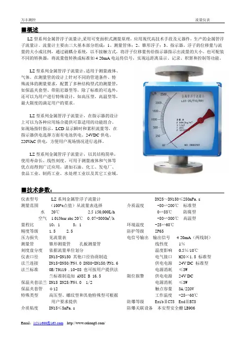
万丰测控 流量仪表■概述LZ 型系列金属管浮子流量计,采用可变面积式测量原理,应用现代高技术手段及元器件,生产的金属管浮子流量计。
流量计主要由三大基本部分组成:1、测量管体;2、锥形浮子;3、指示器。
浮子的位移量与流量的大小成比例,通过磁耦合系统,以不接触方式,将浮子位移量传给指示器指示出流量的大小。
也可配装不同的转换器,将流量值转换成标准如4-20mA 电远传信号,实现远距离显示、记录、积算和控制等功能。
LZ 型系列金属管浮子流量计,适用于测量液体、气体。
在测量管的设计上针对不同的管道条件、特殊流体的测量要求,配置了多种结构型式的测量管,如保温夹套型、带阻尼器型等。
除了标准的可选外,还可以为用户进行特殊设计,如高压型、高温型等,最大限度的满足用户的要求。
LZ 型系列金属管浮子流量计,在指示器的设计上可以为各种应用场合提供可靠适用的功能组合。
如现场指针指示,LCD 显示瞬时和累积流量等,在指示器供电选择方面有电池供电、24VDC 供电、220V AC 供电,方便用户现场情况进行选择。
LZ 型系列金属管浮子流量计,以其结构简单,使用寿命长、线性刻度、可用于测量液体和气体等优点而得到广泛应用,诸如石油、化工、发电厂、食品工业、制药工业、水处理工业以及其它工业域。
■技术参数:仪表型号 LZ 系列金属管浮子流量计 测量范围 (100%点值)从流量表选择水 20℃ 2.5-150,000L/h空气 1.013bar abs 20℃ 0.07-3000m 3/h量程比 10:1 5:1 精度等级 1.5 2.5 压力损失 见流量表测量管 锥形测量管 孔板测量管 刻度盘分度 依据流量单位划分仪表口径 DN15-DN150 其他口径协商制造法兰连接 DN15-DN50/PN4.0 DN80-DN150/PN1.6 法兰标准 GB/T9119 .10-88 也可按用户提供法兰标准制造如 ANSI B 16.5保温夹套法兰 DN15 DN25/PN4.0 1/2 保温夹套管 ф12特殊类型 高压型、螺纹型和其他特殊型可根据用户要求提供介质粘度 DN15≤5mPa.sDN25~DN150≤250mPa.s介质温度 -80∽200℃ 标准型 0∽85℃ 防腐型 -80∽300℃ 高温型 环境温度 -25∽60℃ 防护等级 IP65电信号输出 输出信号 4-20mA (两线制)线性度 1%温度影响 0.5%/10℃电气接口 M20×1.5 标准型 供电电源 24V DC 标准型 电源消耗 ≤3W限位报警 供电电源 24V DC电源消耗 ≤3W触点容量 3A/220V 工作温度 -25∽60℃ 防爆等级 Exib ⅡCT5 Exd ⅡBT5 防爆关联设备 本安型安全栅LB906■型谱LZ Z 就地指示型D 电远传型口径 DN15 25 50 80 100 150结构型式F10 下进上出型(可以缺省)F11 下进侧出型F12 侧进侧出型F13 右进左出型F14 左进右出型接液材质RR0 0Cr18Ni12Mo2Ti 适用于结构型式 F10型 F11型 F12型 F13型 F14型RR1 1Cr18Ni9Ti 适用于结构型式 F10型 F11型 F12型 F13型 F14型RL 316L 适用于结构型式 F10型 F11型 F12型 F13型 F14型RP PTFE 适用于结构型式 F10型Ti 钛合金适用于结构型式 F10型HC 哈氏合金适用于结构型式 F10型附加结构T 夹套型适用于测量器类型 F10型Z 阻尼型适用于测量器类型 F10型 F11型 F12型 F13型 F14型G 高温型适用于测量器类型 F10型 F11型 F12型 F13型 F14型Y 高压型适用于测量器类型 F10型 F11型 F12型 F13型 F14型指示器 (对于远传4-20mA标准电流信号指示器,可以选择+HART协议)缺省现场指针显示瞬时流量ES1 24VDC供电,现场指针显示瞬时流量,角位移变送器,远传4-20mA标准电流信号ES2 24VDC供电,现场指针显示瞬时流量,非接触变送器,远传4-20mA标准电流信号K1 带一上限报警点输出K2 带一下限报警点输出K12 带一上限和一下限报警点输出JSB 电池供电, LCD显示瞬时流量和累积流量JSC 240VAC供电,LCD显示瞬时流量和累积流量JSD 24V DC供电,LCD显示瞬时流量和累积流量JSE 24V DC供电,LCD显示瞬时流量和累积流量,远传4-20mA标准电流信号防爆型式缺省普通型方表头Exi 本安防爆型方表头Exd 隔爆型圆表头举例:LZ□-□□□□□□□注:无选择项可以缺省。
术语Ent Code:ent代码:(输入代码)这个提示只会出现在面板锁打开的情况下。
按↑键每个数字增量。
按←键步到下一个数字。
按E键输入四位数字代码。
如果输入的代码是正确的,显示将提前到下一个菜单提示(Clr合计)。
如果不正确,显示将返回运行模式。
Clr tot: (清除总数)清除(重置)totalizer。
按E键清除总数并返回运行模式。
按M键跳过并推进到下一个菜单选择。
FAC nnUl:(因子乘法器)设置因子乘法器值。
按↑键选择1,10日,100年,1000年。
按E键进入显示值。
FdeC:(因子十进制)为因子设置小数点位置。
这个位置被限制为3(59.999)的地方。
使用这个十进制自动限制了十进制数的位置允许的速度和总到可接受范围。
按←键移动小数点。
按E键选择显示的十进制位置。
注意:为了获得最佳性能和分辨率,在k因子中尽可能多地选择小数。
示例:输入k因子1为1000。
FaC lInear/10poInt:直线/10点:(因子类型)推荐10点线性化选择其k因素随不同的fl费率变化。
这个选择允许用户最多输入10个:不同的频率和10个对应的k因子,为dif fer fl的费率。
在直线的设置是用于fl的电表,它的输出是线性的,在它的整个op er在ing fl的范围。
压停的↑选择所需的关键一步。
按下电子输入显示因子类型的键。
No/yes set10pt:(set 10 point?)此提示允许用户跳过10点设置例程。
选择yes作为初始设置,或者更改当前的10点值。
选择:不跳,也不跳保留现有的值。
FaC:(factor)这个提示出现在所有带有线性输入的单元中。
因子是每单位体积的脉冲传感器。
脉冲/单位体积是由累加器所暗示的当使用描述符时,de scrip tor。
该因子的隐含单位如下:加脉冲/加仑桶,每桶脉冲MCF脉冲/ MCFM3 / M3脉冲空白没有描述符因素从0.001到59999可以使用。
该因子的0值不允许和警告将得到的消息。
/*********************************************************************功能:霍尔流量传感器测流速,霍尔流量传感器的信号输出脚接T1(P3.5)引脚*******************************************************************/#include <reg51.h>sbit DLed1=P2^0;//定义第一位数码管"位选"控制线的别名sbit DLed2=P2^1;//定义第二位数码管"位选"控制线的别名sbit DLed3=P2^2;sbit DLed4=P2^3;unsigned int speed=0;//最后的流速值unsigned int count=0;//在指定时间内记到的外部脉冲数unsigned char k=0;unsigned char code tab[]={0xc0,0xf9,0xa4,0xb0,0x99,0x92,0x82,0xf8,0x80,0x90};void disp(unsigned char x1,unsigned char x2,unsigned char x3,unsigned char x4);//子函数前向声明/*********************************函数名称:void delay1ms(unsigned int k)功能:延时子函数入口参数:延时时长返回值:无**********************************/void delay1ms(unsigned int k){unsigned char n,m;for(m=0;m<k;m++){for(n=0;n<115;n++);}}//===================主函数void main(){unsigned char n;EA=0;TMOD=0x51;//0101 0001,T1纯软件启动,计数模式,工作方式1;T0纯软件启动,定时模式,工作方式1TH0=0x3c;//12M晶振,定时50msTL0=0xb0;ET0=1;//开启定时0中断EA=1;//开启总中断TR0=1;//同时启动定时与计数TR1=1;while(1){speed=(count+3)/11;//运算参考模块说明书for(n=20;n>0;n--)//稳定显示一阵{disp(speed/1000,speed%1000/100,speed%100/10,speed%10);}TR0=1;//再次启动定时和计数功能,为下一次的测量作准备TR1=1;}}/*********************************函数名称:功能:T0中断处理函数说明:定时时间到,则关闭定时器,取出计数值入口参数:返回值:**********************************/void int0_fun() interrupt 1{k++;TH0=0x3c;//重载定时器T0初值TL0=0xb0;if(k>=2)//100ms的定时时间到{TR0=0;TR1=0;count=TH1*256+TL1;TH1=0x00;//清除计数值TL1=0x00;k=0; //清除标志变量}}/********************************功能:显示函数四位数码管的显示函数段选:P1位选:P20-P23注意:采用的共阳数码管***************************/void disp(unsigned char x1,unsigned char x2,unsigned char x3,unsigned char x4) {DLed1=1;DLed2=0;DLed3=0;DLed4=0;//送位码,只让第一位数码管显示P1=tab[x1];//送段码delay1ms(10);//延时P1=0xff;//关闭//----扫描显示第二位数码管------DLed1=0;DLed2=1;DLed3=0;DLed4=0;P1=tab[x2];delay1ms(10);P1=0xff;//----扫描显示第三位数码管------DLed1=0;DLed2=0;DLed3=1;DLed4=0;P1=tab[x3];delay1ms(10);P1=0xff;//----扫描显示第四位数码管------DLed1=0;DLed2=0;DLed3=0;DLed4=1;P1=tab[x4];delay1ms(10);P1=0xff;}。
Metal Tube Rotameter User Manual(Version21)1.Safety Instructions (1)2.Introduction (3)2.1General Description (3)2.3Features (4)2.4Drawing (5)2.5Technical Parameters (9)3.Intended Use (10)4.Wiring (12)5.Limit Switch (15)6.Flow Table (17)7.Operation (19)7.1Main Parameters (19)7.2Clear Total Flow (20)7.34mA correction (21)7.420mA Correction (22)7.5Flow Unit (23)7.6Damp (24)7.7Small Signal Cutoff (25)7.8Measuring Range (26)8.Trouble Shooting (27)1.Safety Instructions Thank you for purchasing ourproduct.Wehavewritten this guide to provide the persons responsible for the installation,operation and maintenance of your flow meter with the product specific information they will need.In order to prevent damage to instrument and make the instrument in the best performance and stable operation,please read this manual thoroughly before installation.Please have a safekeeping of this manual and together with the instrument after reading.Please pass this manual to technical department of end user to keep.This manual classifies important grade of safety attentions by Caution and Warning.Caution Error operation in case of ignoring the tips might cause the personal injury or damage to the instrument and property.WarningError operation in case of ignoring the tips might cause the personal injury or major accident.Select explosion-proof instrument for explosive environment applicationConfirm whether the nameplate of instrument has the identifiers of explosion-proof certification and temperature class,the instrument can ’t be used in explosive environment without those identifiers.The explosion-proof temperature class of instrument must meet the explosion-proof and temperature of environmental requirements on siteWhen the instrument is in used explosion-proof environment,make sure that the explosion-proof certification and temperature class of instrument meet to theThis manual contents the following icons:Indicates safety attentions which are dangerous.Indicates safety attentions which are needed to pay attention to.Indicates safety attentions which are forbidden.requirements on site.No opening while working in explosive environmentBefore wiring,please power instrument off.The protection class of instrument must meet the working conditionrequirements on siteThe requirement of protection class on site should be under or the same as the protection class of instrument to ensure that the instrument is working fine.Confirm the working environment of instrument and medium temperatureThe environment on site and the maximum medium temperature should be under the nominal value of instrument.Confirm the ambient pressure of instrument and medium pressureThe ambient pressure on site and the maximum medium pressure should be under the nominal value of instrument.If doubting that the instrument in the event of failure,please do not operate itIf there are something wrong with the instrument or it had been damaged,please contact us.ImportantBefore use,read this manual thoroughly and familiarize yourself fully with the features,operations and handling of rotameter to have the instrument deliver its full capabilities and to ensure its efficient and correct use.WarningWhen using a metal tube rotameter,the total system design must be considered to ensure safe and troublefree performance.Function,material compatibility,adequate ratings,proper installation,operation,and maintenance are the responsibilities of the system designer and user.Improper selection or misuse of the product may result in serious personal injury or property damage.InformationMetal Tube Rotameter may be used only for flow measurements of fluid and gaseous media.The manufacturer shall not be liable for damages that may result from unintended or inappropriate use.When dealing with an aggressive medium,clarify the material resistance of all wetted parts.When using the device in hazardous areas,follow the applicable national installation rules.CautionInstallation,start-up and operating personnelOnly trained specialists authorized by the system operator may carry out the installation,electrical installations,startup,maintenance and operation.They must read and understand the operating manual and follow its instructions.The required mounting,electrical installation,start-up and maintenance work may only be carried out by expert and authorized persons designated by the plant operator. Basically,follow the conditions and provisions applicable in your country.2.Introduction2.1General DescriptionLZ Series intelligent Metal tube rotameter is a variable area flow meter which is based on the float position measurement.With full-metal structure,it has the features of small size,low pressure loss,large range ratio(10~20:1),optional transmitter with HART communication function,and convenient installation&maintenance etc.It is widely used in flow measurement and process control of small flow,low flow rate, and various industries under complex and harsh environments.2.3Features 1.Robust all-metalstructure design.2.Suitable for gas and liquid measurement in various industries.3.Cone-shape measuring tube design,which has wide measuring range and good linearity.4.Wetted parts material are optional:Stainless steel,Titanium,Hastelloy,PTFE,FEP,etc.5.Adopt advanced magnetic coupling system design,improve the accuracy and stability6.The upper row displays the instantaneous flow,the lower row displays the total flowInstantaneous flow 0.000-99999Total flow 0.00-99999999Current range 3.80-21.00mA Instantaneous flow percentage 0-100%Pointer angle 0.00-90.00°Ambient temperature-40--+150℃Total flow small signal cutoff 0-10%Damping time setting range 0-10secondsVarious flow units are optional,the range is automatically converted when unit is changed.2.2Working PrincipleThe flow meter consists of a measuring tube and a float inside it.The flow pushes the float to an equilibrium point.The area obtained between the float and the tube is proportional to the flow rate.The point of equilibrium depends on:•E =Force of the fluid flow •Ff =Weight of the float •Al =Free area of flowwhere:Al=A0(calibrated orifice area)-Af (float area)7.For the digital LCD display type,the flow range of the instantaneous flow can be corrected on-site based on the different measuring medium.8.It adopts advanced six level data backup technology,data of total flow can be saved automatically when power-off,(the total flow sending period is0.3S).9.Besides AC/DC power supply,it supports battery power supply function.10.No need to open the cover,it can be operated by a magnetic pen;the key operation function is also available.11.Through the HART protocol,you can use the handheld operator or host computer software to perform partial or full configuration operations on the flowmeter.2.4Drawing·Standard Dimensions and WeightCaliber DN15DN25DN50DN80DN100DN150L (mm)250250250250250250Weight (kg) 5.0 6.51015.51735Square Convertor Round Convertor·Jacket Type Dimensions and Weight Caliber DN15DN25DN50DN80DN100DN150L (mm)250250250250250250Weight (kg)7.51013192138·FEP Liner type Dimensions and weight Caliber DN15DN25DN50DN80DN100DN150L (mm)250250250250250250Weight (kg) 5.0 6.51015.516.532Insulation Jacket typeSquare Convertor Round Convertor·FEP Liner type Dimensions and weight Caliber DN15DN25DN50DN80DN100DN150L (mm)250250250250250250Weight (kg) 5.0 6.51015.51732·Side outlet type:Dimensions,weight and pressure loss(DN15~DN25)·Bottom inlet and side outlet type:Dimensions,weight and pressure lossCaliberDN15DN25F(mm)120120L(mm)250250Weight(kg)67.2Pressure loss(kpa)2130CaliberDN15DN25F(mm)120120L(mm)250250H(mm)67.2Weight(kg)67.2Pressure loss(kpa)2130Square Convertor Round(DN15~DN25)·Horizontal mounting type:Dimensions ,weight and pressure loss Caliber 15202540506580100125150L (mm)250250250300300400400400500500(DN15~DN150Gas)Caliber 15202540506580100125150L (mm)250250250250250250250250250250(DN15~DN150Liquid)·Additional structure and installation instructionsStraight pipe type With Filter Liner FEP with Filter Liner FEP straight pipe typeDiameter DN15DN25DN50DN80DN100DN150 Front straight pipe H1≥(mm)75125250400500750 After straight pipe H2≥(mm)250250250250250250φd(mm)951151652002202852.5Technical Parameters3.Intended UseInstallation drawingEx-proof mark Flame-proof :ExdIICT4~6GbIntrinsically Safe Explosion Proof:ExialICT3-6Sensor body SS304FloatSS304,SS316,Hastelloy,FEPh1:Outlet straight pipe h2:Inlet straight pipe,5D h3:Magnetic filter1.Remote type flow meter need to be earth grounded to get good electromagnetic compatibility.2.Upstream section≥5DN and downstream≥250mm to eliminate the whirlpool effect.3.The welding slag in the pipeline must be cleaned,and there mustn't be any magnetic particles in the magnetic coupling part.4.When install anti-corrosion type flow meter,the strength should be moderately when fasten bolts of flanges to avoid damage to the sealing surface.5.Please properly handle the waterproof problem of the cable connector to prevent rainwater from entering the case.6.If there's magnetic particles in the medium,magnetic filter should be installed in the inlet.If there's non-magnetic particles,filter should be installed.If there is bubbles,exhaust should be installed.7.Control valve should be installed in the downstream of flow meter.Working pressure should be more than pressure loss to make sure flow meter can work stably.8.If medium is pulsating flow,a buffer device should be installed.9.Open the control valve slowly to avoid damaging to the flow meter.10.If pressure is unstable,especially for gas,a damping structure should be adopted.4.WiringNote1:When wiring in accordance with intrinsically safe explosion-proof requirements,please combine the wiring method of the relevant safety barrier. Note2:24VDC power supply and pulse output are not in common ground!Note3:Battery powered model,use a specific power socket,no output.Two-wires4-20mA output connection(with HART)Intrinsic safety connectionRelay output and pulse output connectionAC power supply connectionBattery powered connectionHartThe HART375handheld tool can be connected to the HART instrument in the remote control room or on-site for communication operations.The handheld tool can be connected in parallel to the HART protocol device or to its load resistance(250Ω).Don’t need to consider the polarity of the lead when connecting.In order to ensure the normal communication of the handheld tool,there must be a minimum load resistance of250Ωin the loop.The handheld tool does not directly measure the loop current.After checking that the power supply of the meter loop is normal,press the key of the handheld tool for more than one second to turn on it.After the handheld starting,it will automatically search for the HART device with the polling address zero on the 4-20mA loop.Note:The zero-trim function can correct instrument output zero deviation caused by the installation location and it generally can be conducted at the beginning of the HART devices and instruments periodic verification.The use of this feature requires the authorization of the HART instrument owner,or it may cause the error of the output of HART instrument.5.Limit SwitchOne or two limit switches can be installed in the pointer,when it reaches to the set value,the switch will send a alarm signal,the values have been set according to client’s requests before delivery,values also can be set by client.SC3.5-No limit switch is intrinsic safety explosion proof,it should be used together with transistor amplifier WE77/EX1or WE77/EX2.SC3.5-NO limit switch is direct connection type,power supply is24VDC,three wire output is23.5V electric signal to the PLCFlow Range TableSpecial specifications can be customized according to customer’s inquiry.7.1Main Parameters7.2Clear Total Flow7.5Flow Unit7.6Damp7.7Small Signal Cutoff7.8Measuring Range8.Trouble ShootingNote:Above is some normal trouble shooting.If you have any more question,please contact with manufacturer.SMERI s.r.l.Via Mario Idiomi 3/13。
User's Manual杭州米科传感技术有限公司更多资讯请扫二维码服务电话:400-163-1718杭州米科传感技术有限公司涡街流量计使用说明书U-MIK-LUGB-YHCN6第6版前言●感谢您购买本公司产品。
●本手册是关于产品的各项功能、接线方法、设置方法、操作方法、故障处理方法等的说明书。
●在操作之前请仔细阅读本手册,正确使用本产品,避免由于错误操作造成不必要的损失。
●在您阅读完后,请妥善保管在便于随时取阅的地方,以便操作时参照。
注意●本手册内容如因功能升级等有修改时,恕不通知。
●本手册内容我们力求正确无误,如果您发现有误,请与我们联系。
●本手册内容严禁转载、复制。
●本产品禁止使用在防爆场合。
版本U-MIK-LUGB-YHCN6第六版2020年12月I确认包装内容打开包装箱后,开始操作之前请先确认包装内容。
如发现型号和数量有误或者外观上有物理损坏时,请与本公司联系。
产品清单产品包装内容II目录第一章产品概述 (1)1.1产品简介 (1)1.2工作原理 (1)1.3技术参数 (2)1.4功能与特点 (5)第二章外形结构尺寸与安装 (7)2.1外形结构与尺寸 (7)2.2安装指南 (8)2.3接线及调试 (10)第三章可测工况流量范围 (12)第四章界面显示 (15)第五章菜单设置 (18)5.1各键功能 (18)5.2主菜单 (18)5.3参数设置菜单 (18)第六章输出形式的设置方法(仅E3使用) (25)第七章线性修正系数的设置方法 (26)第八章维护与检修 (28)8.1故障及排除 (28)第九章质保及售后服务 (29)第十章通讯协议 (30)10.1相关参数 (30)10.2数据格式 (30)10.3数据地址 (30)III10.4特殊传输数据 (31)附录1放大器线路连接图 (32)附录2仪表标定方法 (34)附录3基本公式 (35)IV第一章产品概述-1-第一章产品概述1.1产品简介涡街流量计是一种应用卡门涡街原理的流量计,用于测量液体、气体和蒸汽的流量,也可测量含有微小颗粒、杂质的浑浊液体,广泛应用于石油、化工、制药、造纸、冶金、电力、环保、食品等行业。