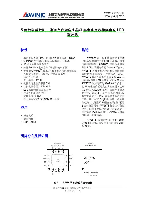
BZD27C5V1P中文资料
- 格式:pdf
- 大小:241.94 KB
- 文档页数:7
Document Number 17249Zener Diodes with Surge Current SpecificationFeatures•Sillicon Planar Zener Diodes•Low profile surface-mount package•Zener and surge current specification •Low leakage current •Excellent stability•High temperature soldering:260°C/10 sec. at terminals •Lead (Pb)-free component•Component in accordance to RoHS 2002/95/EC and WEEE 2002/96/ECMechanical DataCase: JEDEC DO-219AB (SMF ®) Plastic case Weight: approx. 15 mgPackaging codes/options:GS18 / 10 k per 13 " reel, (8 mm tape), 50 k/box GS08 / 3 k per 7 " reel, (8 mm tape), 30 k/boxAbsolute Maximum RatingsT amb = 25°C, unless otherwise specified1)Mounted on epoxy-glass PCB with 3 x 3 mm Cu pads (≥ 40 µm thick)2) T J= 25°C prior to surgeThermal CharacteristicsT amb = 25°C, unless otherwise specified1)Mounted on epoxy-glass PCB with 3 x 3 mm Cu pads (≥ 40 µm thick)Electrical CharacteristicsT amb = 25°C, unless otherwise specifiedParameterT est conditionSymbol Value Unit Power dissipationT L = 80°C P tot 2.3W T A = 25°CP tot 0.81)W Non-repetitive peak pulse power dissipation100 µs square pulse 2)P ZSM 300W 10/1000 µs waveform (BZD27-C7V5P to BZD27-C100P)2)P RSM 150W 10/1000 µs waveform (BZD27-C110P to BZD27-C200P)2)P RSM100WParameterTest condition Symbol Value Unit Thermal resistance junction to ambient air 1)R thJA 180K/W Thermal resistance junction to lead R thJL 30K/W Maximum junction temperature T j 150°C Storage temperature rangeT S- 55 to + 150°CParameterT est conditionSymbol MinT yp.Max Unit Forward voltage I F = 0.2 AV F1.2V Document Number 85810Electrical CharacteristicsWhen used as voltage regulator diodes (T J = 25°C unless otherwise noted)1)Pulse test: tp ≤ 5 ms.PartnumberMarking CodeWorking Voltage 1)Differential Resistance Temperature Coefficient T est Current Reverse Current at Reverse Voltage V Z @ I ZTr dif @ I ZαZ @ I Z I ZT I R V R V Ω%/°C mA µA Vminmax typ max min max max BZD27C3V6P D0 3.4 3.848-0.14-0.041001001BZD27C3V9P D1 3.7 4.148-0.14-0.04100501BZD27C4V3P D24 4.647-0.12-0.02100251BZD27C4V7P D3 4.4537-0.10100101BZD27C5V1P D4 4.8 5.436-0.080.0210051BZD27C5V6P D5 5.2624-0.040.04100102BZD27C6V2P D6 5.8 6.623-0.010.0610052BZD27C6V8P D7 6.47.21300.07100103BZD27C7V5P D877.91200.07100503BZD27C8V2P D97.78.7120.030.08100103BZD27C9V1P E08.59.6240.030.0850105BZD27C10P E19.410.6240.050.095077.5BZD27C11P E210.411.6470.050.15048.2BZD27C12P E311.412.7470.050.15039.1BZD27C13P E412.414.15100.050.150210BZD27C15P E513.815.65100.050.150111BZD27C16P E615.317.16150.060.1125112BZD27C18P E716.819.16150.060.1125113BZD27C20P E818.821.26150.060.1125115BZD27C22P E920.823.36150.060.1125116BZD27C24P F022.825.67150.060.1125118BZD27C27P F125.128.97150.060.1125120BZD27C30P F228328150.060.1125122BZD27C33P F331358150.060.1125124BZD27C36P F4343821400.060.1110127BZD27C39P F5374121400.060.1110130BZD27C43P F6404624450.070.1210133BZD27C47P F7445024450.070.1210136BZD27C51P F8485425600.070.1210139BZD27C56P F9526025600.070.1210143BZD27C62P G0586625800.080.1310147BZD27C68P G1647225800.080.1310151BZD27C75P G27079301000.080.1310156BZD27C82P G37787301000.080.1310162BZD27C91P G48596602000.080.135168BZD27C100P G594106602000.090.135175BZD27C110P G6104116802500.090.135182BZD27C120P G7114127802500.090.135191BZD27C130P G81241411103000.090.1351100BZD27C150P G91381561303000.090.1351110BZD27C160P H01531711503500.090.1351120BZD27C180P H11681911804000.090.1351130BZD27C200PH21882122005000.090.1351150Document Number Electrical CharacteristicsWhen used as protection diodes (T J = 25°C unless otherwise noted)1)Non-repetitive peak reverse current in accordance with "IEC 60-1, Section 8" (10/1000 µs pulse); see Fig. 5.PartnumberRev. Breakdown Voltage Test Current T emperature Coefficient Clamping VoltageReverse Current at Stand-Off Voltage V (BR)R at I testI test αZ @ I test V C at I RSM 1)I R at V WMV mA%/°C V A µA V minminmax max max BZD27C7V5P 710000.0711.313.31500 6.2BZD27C8V2P 7.71000.030.0812.312.21200 6.8BZD27C9V1P 8.5500.030.0813.311.31007.5BZD27C10P 9.4500.050.0914.810.1208.2BZD27C11P 10.4500.050.115.79.659.1BZD27C12P 11.4500.050.1178.8510BZD27C13P 12.4500.050.118.97.9511BZD27C15P 13.8500.050.120.97.2512BZD27C16P 15.3250.060.1122.9 6.6513BZD27C18P 16.8250.060.1125.6 5.9515BZD27C20P 18.8250.060.1128.4 5.3516BZD27C22P 20.8250.060.1131 4.8518BZD27C24P 22.8250.060.1133.8 4.4520BZD27C27P 25.1250.060.1138.1 3.9522BZD27C30P 28250.060.1142.2 3.6524BZD27C33P 31250.060.1146.2 3.2527BZD27C36P 34100.060.1150.13530BZD27C39P 37100.060.1154.1 2.8533BZD27C43P 40100.070.1260.7 2.5536BZD27C47P 44100.070.1265.5 2.3539BZD27C51P 48100.070.1270.8 2.1543BZD27C56P 52100.070.1278.6 1.9547BZD27C62P 58100.080.1386.5 1.7551BZD27C68P 64100.080.1394.4 1.6556BZD27C75P 70100.080.13103.5 1.5562BZD27C82P 77100.080.13114 1.3568BZD27C91P 8550.090.13126 1.2575BZD27C100P 9450.090.13139 1.1582BZD27C110P 10450.090.131390.72591BZD27C120P 11450.090.131520.655100BZD27C130P 12450.090.131690.595110BZD27C150P 13850.090.131870.535120BZD27C160P 15350.090.132050.485130BZD27C180P 16850.090.132290.435150BZD27C200P18850.090.132540.395160 Document Number 85810Typical Characteristics (Tamb = 25 °C unless otherwise specified)Figure 2. Typ. Diode Capacitance vs. Reverse Voltage Figure 3. Power Dissipation vs. Ambient Temperature17411F I – F o r w a r d C u r r e n t ( A )0.00.5 1.0 1.5 2.0 2.5 3.017412C – T y p . J u n c t i o n C a p a c i t a n c e ( p F )D V R – Reverse Voltage (V)0.00.51.01.52.02.53.00255075100125150T amb – Ambient T emperature ( q C )17413P –P o w e r D i s s i p a t i o n ( W )t o t Figure 4. Maximum Pulse Power Dissipation vs. Zener VoltageFigure 5. Non-Repetitive Peak Reverse Current Pulse Definition0204060801001201401600255075100125150175200V Znom – Zener Voltage ( V )17414P –M a x . P u l s e P o w e r D i s s i p a t i o n ( W )R S M IPackage Dimensions in mm (Inches)Document Number Blistertape for SMF Document Number 85810Ozone Depleting Substances Policy StatementIt is the policy of Vishay Semiconductor GmbH to1.Meet all present and future national and international statutory requirements.2.Regularly and continuously improve the performance of our products, processes, distribution and operatingsystems with respect to their impact on the health and safety of our employees and the public, as well as their impact on the environment.It is particular concern to control or eliminate releases of those substances into the atmosphere which are known as ozone depleting substances (ODSs).The Montreal Protocol (1987) and its London Amendments (1990) intend to severely restrict the use of ODSs and forbid their use within the next ten years. Various national and international initiatives are pressing for an earlier ban on these substances.Vishay Semiconductor GmbH has been able to use its policy of continuous improvements to eliminate the use of ODSs listed in the following documents.1.Annex A, B and list of transitional substances of the Montreal Protocol and the London Amendmentsrespectively2.Class I and II ozone depleting substances in the Clean Air Act Amendments of 1990 by the EnvironmentalProtection Agency (EPA) in the USA3.Council Decision 88/540/EEC and 91/690/EEC Annex A, B and C (transitional substances) respectively. Vishay Semiconductor GmbH can certify that our semiconductors are not manufactured with ozone depleting substances and do not contain such substances.We reserve the right to make changes to improve technical designand may do so without further notice.Parameters can vary in different applications. All operating parameters must be validated for each customer application by the customer. Should the buyer use Vishay Semiconductors products for any unintended or unauthorized application, the buyer shall indemnify Vishay Semiconductors against all claims, costs, damages, and expenses, arising out of, directly or indirectly, any claim of personal damage, injury or death associated with such unintended or unauthorized use.Vishay Semiconductor GmbH, P.O.B. 3535, D-74025 Heilbronn, GermanyDocument Number 。