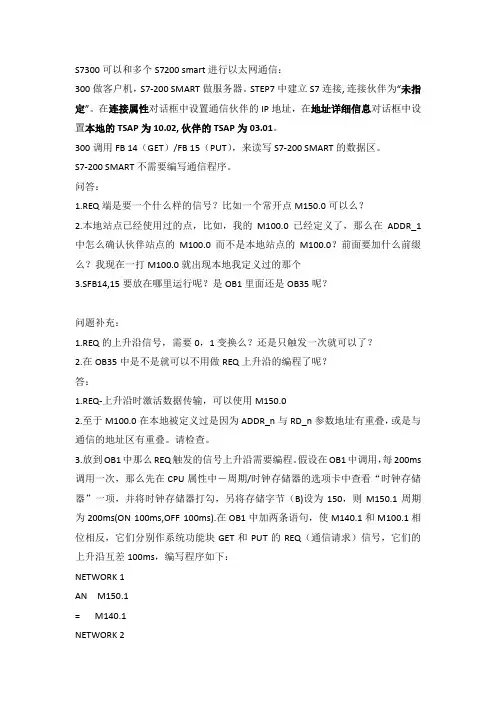
S7-200_与S7300的以太网通讯
- 格式:doc
- 大小:809.00 KB
- 文档页数:12
Entry ID: 17369594
Date: 10/16/2003
QUESTION:
How do I configure an S7 connection for data communication between an S7-200 and an S7-300 via
Ethernet?
ANSWER:
The configuration of an S7 connection between an S7-200 and an S7-300 via Ethernet has to be done
on the one hand in STEP 7 Micro/WIN with the Ethernet Wizard for the S7- 200 and on the other in
NetPro for the S7-300. For the Ethernet communication between the two stations you need
communication processors and CPUs that support S7 communication. In this entry we have explained
all the settings required for the S7-200 and the S7-300 using a sample configuration with CPU 226,
CP243-1, CPU 315-2DP and CP343-1.
Configuration of the CP243-1 using the Ethernet Wizard of STEP 7 Micro/WIN
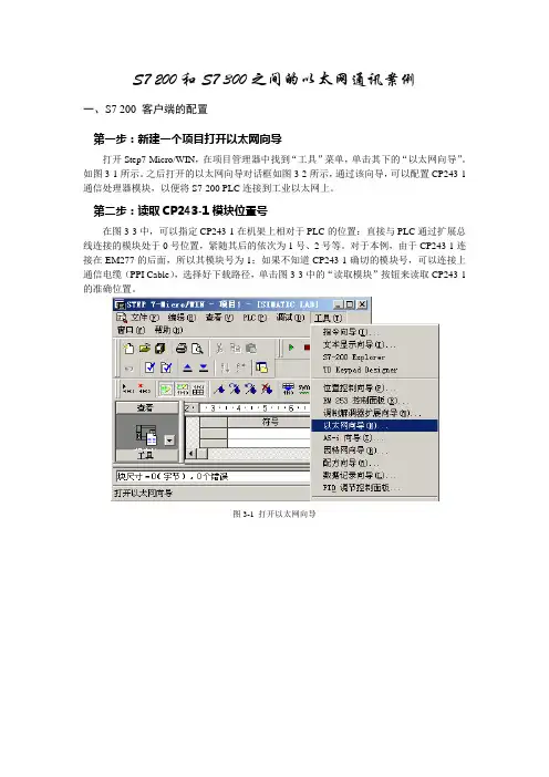
1. Open STEP 7 Micro/WIN and then start the Ethernet Wizard via "Tools > Ethernet Wizard...".
Fig. 1: Starting the Ethernet Wizard
2. In the first step of the Wizard is a description of the Ethernet Wizard. Click on "Next" to start
the configuration process.
Fig. 2: Description of the Ethernet Wizard
3. In the window that is displayed you are informed that your STEP 7 Micro/WIN project must be compiled and be in Symbolic Addressing mode. Acknowledge the message with "Yes".
Fig. 3: Compiling the project and enabling the Symbolic Addressing mode
4. If you are connected with the CP243-1 in your S7-200 station, you can determine the module
position of the CP243-1 automatically via the "Read Modules" button. You can also enter the
module position manually. Click on "Next".
Fig. 4: Determining the module position
5. Define a unique IP address for the CP243-1 and specify the associated subnetwork mask. Acknowledge the settings with "Next".
Fig. 5: Defining the IP address and subnetwork mask for the CP243-1
6. In our example we need an S7 connection for communication to the S7-300. So, for "Number
of connections to configure for this module" you enter "1". Click on "Next".
Fig. 6: Number of S7 connections
7. The dialog for configuring the S7 connection opens. The S7 connection can be configured as
a client or server connection. In our example we have used a client connection for the data
transfer, i.e. the S7 connection is set up actively by the CP243-1.
• Enter the TSAP for connection identification between the two stations. The first part of the
TSAP (xx.) is taken from 10 + connection number, and the second part (.xx) of the TSAP is
taken from the rack number and the slot of the CP343-1.
In our example the TSAP is 10.07, i.e. the connection number = 0, the rack number = 0 and
the slot of the CP = 7.
• Enter the IP address of the CP343-1.
• Specify a symbolic name for the connection.
Click on the "Data Transfers" button to define a new data transfer for this connection.
Fig. 7: Connection configuration
8. In order to read data from the S7-300 you select "Read data from the remote server
connection". Enter the number of data bytes to be read from the server and specify where this
data is located in the S7-300. Define a storage area in the S7-200 for the data read. Assign a
symbolic name for the data transfer. Acknowledge the settings with "OK".
Fig. 8: Configuring the data transfer
9. Since the configuration of the CP243-1 module may no longer be changed, you select the
setting with CRC protection. You can specify the Keep Alive Interval with the default time.
Click on "Next".
Fig. 9: CRC protection and Keep Alive Interval
10. Select a free address area for storing the configuration.
Fig. 10: Selecting a storage area for the configuration
11. Close the Ethernet Wizard with "Finish". The Ethernet Wizard generates the project
components required.
Fig. 11: Closing the Ethernet Wizard
12. In the main program ("MAIN (OB1)") you add the call of the ETH0_CTRL (communication
setup) and the call of the ETH0_XFR (read data packages). The parameters "Chan_ID" and
"Data" of the ETH0_XFR block can be selected with a right-click.
Fig. 12: Adding the program code in the main program
13. Save the configuration and load it in the S7 200. Configuring an unspecified S7 connection in NetPro
1. Open your STEP 7 project with the configured SIMATIC S7-300 station and switch to NetPro via "Options > Configure Network".
Fig. 13: Starting NetPro
2. Mark the CPU in the SIMATIC S7-300 station and create a connection via "Insert > New Connection...".
Fig. 14: Inserting a new connection