经济型B2900A 系列精密型源表配置指南
- 格式:pdf
- 大小:1.07 MB
- 文档页数:12

FMA-900 SERIESAir Velocity TransducersStandardRemote Probee-mail:**************For latest product manuals:User’sGuideShop online atIt is the policy of OMEGA Engineering, Inc. to comply with all worldwide safety and EMC/EMI regulations that apply. OMEGA is constantly pursuing certification of its products to the European New Approach Directives. OMEGA will add the CE mark to every appropriate device upon certification.The information contained in this document is believed to be correct, but OMEGA accepts no liability for any errors it contains, and reserves the right to alter specifications without notice.WARNING: These products are not designed for use in, and should not be used for, human applications.General DescriptionThe OMEGA ®FMA-900 air velocity mass flow transducer is ideal for economical monitoring of clean air flows in ducts and pipes, while producing very little permanent pressure drop in the flowstream The FMA-900 employs two rugged glass-coated RTD elements, protected by a 1⁄4" diameter 304SS tube with a“window” cut out. One RTD is the velocity sensor, while the other RTD provides ambient air temperature compensation. The velocity sensor is heated to maintain a constant (approximately 30°C) temperature differential above the ambient air temperature, as measured by the second RTD element. The cooling effect of the air flow experienced by the velocity sensor is measured and converted to an electrical output signal proportional to air velocity. The FMA-900 is provided with a 13" long probe as standard. The 304SS tubing is provided with inch marks for ease of insertion depth.UnpackingThe following items are supplied with the FMA-900:•FMA-900 Series Air Velocity Transducer •Mating connector•Removable plastic protective cover (supplied on the sensor tip)•Operator’s manual1-1Important Considerations Before Installationintrinsically safe. Do not use for flammable or hazardous gases, or inhazardous areas.The FMA-900 air velocity transducer is intended for use with clean air or !nitrogen ONLY. Do not use with other gases, as other gases will produce anuncalibrated, non-linear output signal. In addition, air carrying dust or oil (suchas found in blower/compressor systems that utilize oil) can lead to coating of thesensor and thus, inaccurate readings. Refer to the Maintenance section for moreinformation on cleaning the sensor.The FMA-900 is a bi-directional device; flow in the forward or reverse directionprovides the same output.Installing the FlowmeterThe FMA-900 air velocity transducer can be mounted vertically or horizontallywithout shift in calibration.1.Remove the plastic protective cap from the sensor tip.2.Run a length of straight pipe before and after the flowmeter. The amount ofupstream straight pipe run required depends upon the type of obstruction whichis immediately upstream of the flow sensor. See Table 2-1 for specificrequirements. Downstream of the flow sensor, in all situations, run 5 diametersof straight pipe, regardless of the downstream obstruction.3.Align the FMA-900 with the air flow. Make sure the width of the electronics box(2 inches) is parallel with the flow stream.The score line on the tubing is another way of aligning the air flow sensor withthe flow stream. The score line starts from the center of the transducer windowand as a result it can be aligned properly.One means of installing the probe into a flow stream is to utilize a compressionfitting, such as OMEGA’s SSLK-14-14 stainless steel compression fitting withTeflon ferrules, which permits adjustment of the insertion depth of the probe.On Remote Probe Models (-R), connect the remote probe cable to the ElectronicHousing.1-2Table 2-1 Piping Requirements1-3Wiring the Flowmeter1.Connect pins as follows:PLUG PIN NO.DESCRIPTION1 0-5 Vdc or 4-20 mA Output (−)2 0-5 Vdc or 4-20 mA Output (+)3Power Supply (+)4No Connection5No Connection6Power Supply (−)2.Blow clean air through the FMA-900.3.Install the sensor into the pipe or duct.Measuring Air FlowThe FMA-900 measures standard velocity, which is the mass velocity of the airreferenced to 25°C and 760 mm Hg. No temperature or pressure corrections arerequired. Where SCFM (standard cubic feet per minute) measurements aredesired:1.Locate the point of average velocity in the pipe or duct.2.In round pipes, under turbulent flow conditions (where the Reynolds number isgreater than 5,000), mount the velocity sensor approximately 1⁄8of a pipediameter in from the the pipe wall. For example, in an 8" diameter pipe, mountthe probe 1" in from the pipe wall.3.For pipes or ducts where the flow is not turbulent, or the flow profile is notsymmetrical (due to inadequate straight pipe runs, etc.), perform a traverse ofthe duct, in accordance with standard duct traversal methods as recommendedby ASHRAE or the National Air Balance Council.4.To obtain SCFM, once the probe is mounted in the location of average velocity,multiply the average velocity readings (in SFPM, standard feet per minute) bythe cross-sectional area of the pipe or duct, in square feet. For standard pipe,these values can be found in the technical section of the OMEGA CompleteFlow and Level Measurement Handbook and Encyclopedia®. MaintenanceExcept for intermittent removal of the sensor from the line for cleaning, there isno routine maintenance for the FMA-900. If the probe becomes coated with dust,blow the dust away with clean air. If the probe is coated with sticky material,clean it with a solvent which is compatible with epoxy, glass, and 304SS, andwhich will not leave a residue on the sensor. You may clean the sensor withwater or alcohol (Ethanol) and an artist’s brush.CalibrationEach FMA-900 is individually calibrated in a NIST-traceable wind tunnel. Forcalibration certification or calibrating to a new range, the unit must be returnedto OMEGA. To obtain an Authorized Return (AR) number, call the OMEGACustomer Service Department with a Purchase Order number to cover therecalibration charges.1-4SpecificationsRanges:Model No.Model No.0-5 V Output4-20 mA Output RangeFMA-900-V FMA-900-I0-100 SFPMFMA-901-V FMA-901-I0-200 SFPMFMA-902-V FMA-902-I0-500 SFPMFMA-903-V FMA-903-I0-1000 SFPMFMA-904-V FMA-904-I0-2000 SFPMFMA-905-V FMA-905-I0-5000 SFPMFMA-906-V FMA-906-I0-10,000 SFPMAccuracy:±1.5% of Full Scale at room temperature. Add ±0.5% of readingfrom 32 to 122°. Add 1% Full Scale below 1,000 SFPM.Repeatability:±0.2% of Full ScaleResponse Time:400 milliseconds to within 63% of final value at room temperatureProbe:Aluminum oxide ceramic glass coating and epoxy;probe body 304SSProbe Temperature/-40 to 250°F (-40 to 121°C); 150 PSIG maximumPressure:Remote Probe (-R):Available with 15' (4.6 m) shielded cable between the Probe andthe Electronic HousingElectronics TemperatureRange:Operating: 32 to 122°F (0 to 50°C)Storage: 32 to 158°F (0 to 70°C)Ambient TemperatureCompensation:About 5 minutes for 20°F ambient temperature changePower:15 to 18 Vdc at 300 mA(15 to 24 Vdc at 300 mA for 0-100 SFPM and 0-200 SFPM ranges)Output Load Resistance:Voltage: 250 ohms minimumCurrent: 0-400 ohms maximum; 4-wireAccessories:Mating connector prewired to 15 feet shielded cable with built-inferrite core includedDimensions:Case: 3.5" H x 2" W x 1.25" D(89 mm H x 51 mm W x 31.8 mm D)Probe: 1/4" (6.35 mm) O.D., 13" long standard (330 mm),3.75" long optional (“-S”)Weight:0.35 lbs. (0.16 kg)1-5OTHER IMPORTANT CONSIDERATIONS BEFORE INSTALLATION----------------------------------------------------------------CAUTION----------------------------------------------------Follow All Safety Precautions and Operating Instructions Outlined in this Manual.The Unit May be Powered from a DC Power Supply. The Power Supply Should HaveIntegral Impedence Protection.Recommended Wiring Cable: Shielded 4-Conductor Cable, 22 or 24 AWG Stranded.Recommended Power Supply Rating: 0-24 Vdc @ 300 mA, 7.2 VAThere are No User Replaceable Fuse in this Product.Avoid Contact with Hazardous Live Parts.Do Not Operate in Flammable or Explosive Environments.This Product is for Use Only with Equipment which has no Accessible Live Parts.------------------------------------------------------------------------------------------------------------------------------------------------------------------------------------------------------------------------------------------------------------------------TYPICAL INSTALLATION SCHEMATIC1-6Direct all warranty and repair requests/inquiries to the OMEGA Customer Service Department. BEFORE RET URNING ANY PRODUCT(S) T O OMEGA, PURCHASER MUST OBTAIN AN AUT HORIZED RET URN (AR) NUMBER FROM OMEGA’S CUST OMER SERVICE DEPART MENT (IN ORDER T O AVOID PROCESSING DELAYS). The assigned AR number should then be marked on the outside of the return package and on any correspondence.The purchaser is responsible for shipping charges, freight, insurance and proper packaging to prevent breakage in transit.FOR WARRANTY RETURNS, please have the following information available BEFORE contacting OMEGA:1.Purchase Order number under which the productwas PURCHASED,2.Model and serial number of the product underwarranty, and3.Repair instructions and/or specific problemsrelative to the product.FOR NON-WARRANTY REPAIRS,consult OMEGA for current repair charges. Have the following information available BEFORE contacting OMEGA: 1. Purchase Order number to cover the COSTof the repair,2.Model and serial number of the product, and3.Repair instructions and/or specific problemsrelative to the product.OMEGA’s policy is to make running changes, not model changes, whenever an improvement is possible. This affords our customers the latest in technology and engineering.OMEGA is a registered trademark of OMEGA ENGINEERING, INC.© Copyright 2006 OMEGA ENGINEERING, INC. All rights reserved. T his document may not be copied, photocopied, reproduced, translated, or reduced to any electronic medium or machine-readable form, in whole or in part, without the prior written consent of OMEGA ENGINEERING, INC.Where Do I Find Everything I Need for Process Measurement and Control?OMEGA…Of Course!Shop online at TEMPERATUREⅪߜThermocouple, RTD & Thermistor Probes, Connectors, Panels & AssembliesⅪߜWire: Thermocouple, RTD & ThermistorⅪߜCalibrators & Ice Point ReferencesⅪߜRecorders, Controllers & Process MonitorsⅪߜInfrared PyrometersPRESSURE, STRAIN AND FORCEⅪߜTransducers & Strain GagesⅪߜLoad Cells & Pressure GagesⅪߜDisplacement TransducersⅪߜInstrumentation & AccessoriesFLOW/LEVELⅪߜRotameters, Gas Mass Flowmeters & Flow ComputersⅪߜAir Velocity IndicatorsⅪߜTurbine/Paddlewheel SystemsⅪߜTotalizers & Batch ControllerspH/CONDUCTIVITYⅪߜpH Electrodes, Testers & AccessoriesⅪߜBenchtop/Laboratory MetersⅪߜControllers, Calibrators, Simulators & PumpsⅪߜIndustrial pH & Conductivity EquipmentDATA ACQUISITIONⅪߜData Acquisition & Engineering SoftwareⅪߜCommunications-Based Acquisition SystemsⅪߜPlug-in Cards for Apple, IBM & CompatiblesⅪߜDatalogging SystemsⅪߜRecorders, Printers & PlottersHEATERSⅪߜHeating CableⅪߜCartridge & Strip HeatersⅪߜImmersion & Band HeatersⅪߜFlexible HeatersⅪߜLaboratory HeatersENVIRONMENTALMONITORING AND CONTROLⅪߜMetering & Control InstrumentationⅪߜRefractometersⅪߜPumps & TubingⅪߜAir, Soil & Water MonitorsⅪߜIndustrial Water & Wastewater TreatmentⅪߜpH, Conductivity & Dissolved Oxygen InstrumentsM1893/0305。
拟 制: 熊宠魏2008-09-01 图 号OKRW2.702.485SS 1 概述DTSD341/DSSD331(配置号为ME2(SN))三相电子式多功能电能表是一款符合DL/T 614《多功能电能表》标准的0.2S 级和0.5S 级三相电子式多功能电能表。
其主要特点为计量信号为数字流输入、高速的数据处理能力、电源采用双路外接电源供电。
适用于采用IEC61850-9-1/2标准协议的电能计量体系。
DTSD341/DSSD331(配置号为ME2(SN))三相电子式多功能电能表的研发与生产符合以下标准: GB/T 15543《电能质量 三相电压允许不平衡度》 GB/T 17882《2级和3级静止式交流无功电能表》GB/T 17883《0.2S 级和0.5S 级静止式交流有功电能表》 DL/T 614 《多功能电能表》DL/T 645 《多功能电能表通信规约》(威胜公司对此协议有扩展) IEC61850-9-2 《数字化变电站通信规约》 1.1 工作原理DSSD331/DTSD341(配置号为ME2(SN))三相电子式多功能电能表是一款遵循IEC61850-9-2LE (数字化变电站内通信规约)协议的全新的数字接口式多功能电能表,采用当今世界流行的高档电能表设计方案:数字信号处理器与中央微处理器相结合的构架,将数字信号处理器的高速数据吞吐能力与中央微处理器 复杂的管理能力完美结合。
通过协议处理芯片获取合并单元的数据协议包,传送至数字信号处理单元完成对电参量测量,电能累计以及电能的计算等任务,后与中央微处理器进行数据交换,由中央微处理器最终完成表计的显示,数据统计,储存,人机交互,数据交换等复杂的管理功能。
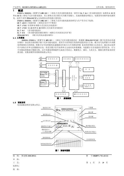
其整表硬件原理框图如图1所示。
图 1 原理框图1.2 面板说明电表面板说明详见图2图2 面板布置图1.4 技术参数1.4.1 基本技术参数1.4.2 日历时钟参数注:内部电池仅用于内部时钟1.4.3 脉冲输出参数脉冲常数:(出厂默认值)*脉冲常数可根据用户要求调整!电气参数:1.4.4 其他参数2术语2.1 需量周期(Demand interval)测量平均功率的连续相等的时间间隔。

PRIMERGY BX900 System Unit System configurator and order-information guideContentsInstructionsConfiguration diagram Configurator I 1BX900 System UnitsII 2BX900 Server BladesIII 3BX900 Storage BladesIV 4Connection Blade OverviewV 5Connection Blades EthernetVI 6Connection Blades Fibre ChannelVII 7Connection Blade InfiniBandVIII 8Connection Blade SASChange reportPRIMERGY ServerJune 2012InstructionsThis document contains basic product and configuration information that will enable you to configure your system viaSystem-Architect.Only the tool "System-Arcitect" will ensure a fast and proper configuration of your PRIMERGY server or your complete PRIMERGY Rack system.Please pay attention to the naming conventions: BX900 S1System unit 1st generationYou can configure your individual PRIMERGY server in order to adjust your specific requirements.The System configurator is divided into several chapters that are identical to the current price list and PC-/ System-Architect.Please follow the lines. If there is a junction, you can choose which way or component you would like to take. Go throughthe configurator by following the lines from the top to the bottom.In one chapter you can only select as many components (here 3x) as the arrow indicates.3xPlease note that there are information symbols which indicate necessary information.For further information see:/products/standard_servers/index.html(internet)https:///com/order-supply/configurators/primergy_config/Pages/Currentconfigurators.aspx(extranet)Prices and availability see price list and PC-/ System-ArchitectSubject to change and errors exceptedFujitsu Technology Solutions x86 PRIMERGY Server 2 of 16Configuration diagram BX900 S1 System Unit S l o t 1S l o t 2s S l o t 3S l o t4Sl o t 17s S l o t 5S l o t 6S l o t 7s Sl ot8S l o t 9S l o t 10s S l o t 11S l o t 12S l o t 18s S l o t 13S l o t 14S l o t 15s Sl ot16Slots with the suffix "s" also support Storage BladesIncluded in basic unit PSU slots may also be equipped with Rear Fan Modules(see next page for details on power and cooling)OptionExtension slots front sideFujitsu Technology Solutions x86 PRIMERGY Server 3 of 16System configurator and order-information guidePRIMERGY BX900 System Unit Status: 2012-05-29 2Section II BX900 Power OverviewConfiguration OverviewA BX900 chassis has 6 slots for power supplies (PSUs) or Fan Units (RFNs). Limiting factors for mounting bladesare available power from PSUs but also cooling which is assured by PSUs or RFNs. As a result there are mountingrules to be followed for servers if less than 6 units (PSUs or RFNs) are used in a BX900 chassis.Also available PSU power has to be considered.Power table BX900E.g. 3+1 means there are 3 base PSUs and 1 redundant unit given.2nd column shows the number of additional Rear Fan Units (RFNs). They are needed to provide coolingto additional server blade slots.Finally there are further columns showing the different server blades. Here is shown their maximum countwhich can be operated with the PSU / RFN configuration given on the left.Not all configurations may make sense, recommended ones are highlighted green.Shown here is a configuration with one kind of server blade, only, no mixed configuration.!Example: A BX900 with 3 standard PSUs at 230VAC and one RFN can support a maximumof 10 BX920 servers.Connection Blades:Above tables are calculated with the assumption that 6 Connection Blades (50W each) are mountedRemark:Basically mixed configurations of blades are possible. Because of the manyfold of possible combinationsextra calculations are required to show configuration limits.Fujitsu Technology Solutions x86 PRIMERGY Server 6 of 16Fujitsu Technology Solutions x86 PRIMERGY Server7 of 16Fujitsu Technology Solutions x86 PRIMERGY Server8 of 16System configurator and order-information guide R PRIMERGY BX900 System Unit Status: 2012-05-29Section IV Connection Blade OverviewEach PRIMERGY BX900 Server Blade comes with onboard Ethernet LAN channelsand special connectors for the optional mezzanine cards.Example BX920 S2: 4 x 1GbE onboard and 2 x Mezzanine slotsDual Server Blade ConnectivityQuad Server Blade ConnectivityR1Fujitsu Technology Solutions x86 PRIMERGY Server9 of 16System configurator and order-information guidePRIMERGY BX900 System Unit Status: 2012-05-29Mezzanine Cards released for BX9xx Server Blades System onboard Mezzanine Mezzanie Card OptionsLAN ports Slots Eth 1Gb 4 Port FC 8Gb 2 Port IB 40Gb 2 Port Eth 10Gb 2 Port SAS HBA Mezz SAS RAID MezzS26361-F3331-E1S26361-F3874-E1S26361-F3992-E2S26361-F3997-E1S26361-F4480-E1S26361-F4481-E1BX920 S1 4x 1GbE 2x x x xBX920 S2 4x 1GbE 2x x x x x x BX922 S2 4x 1GbE 2x x x x x x BX924 S2 2x 10GbE 2x x x x x x BX960 S1 4x 10GbE 4x x xR1Connection Blades released for BX900 S1 System Unit :Order number Connection Blade Type installable in CB Slot S26361-K1366-V100S26361-K1304-V200S26361-K1305-V14S26361-K1305-V126S26361-K1305-V26S26361-K1363-V18S26361-K1365-V18S26361-K1336-V200S26361-K1391-V300PY CB SAS Switch 6Gb 18/6There is no Connection Blade included in the System Unit.SS26361-K1304-V100 1/2 3/4 5/6 7/83/4 5/63/4 5/63/4 5/6PY CB Eth Switch/IBP 1Gb 36/12 1/2 3/4 5/6 7/8PY FC SW 8G 18/8 26 Perform (Brocade)PY CB Eth Switch/IBP 1Gb 36/8+2 PY CB Eth Switch/IBP 1Gb 18/6518x 6Gb SAS 3/4 5/6 7/818x 40Gb IB 18x 40Gb IB (QSFP)3/4 5/618x 4 / 8Gb FC 18x 10Gb Eth (SFP+)6x 6Gb SAS (SFF8088)8x 8Gb FC (SFP+)PY FC SW 8G 18/8 26 Port (Brocade)PY CB IB Switch 40Gb 18/18PY CB Eth Pass Thru 10Gb 18/18 1/2 3/4 5/6 7/818x 10Gb Eth 18x 8Gb FC (SFP+)18x 8Gb FC S26361-K1304-V101 1/2 3/4 5/6PY FC Switch 8Gb 18/8 14 Port (Brocade)18x 8Gb FC 18x 10Gb Eth PY CB FC Pass Thru 8G 18/18 1/2 3/4 5/6 7/818x 8Gb FC 8x 8Gb FC (SFP+)8x 8Gb FC (SFP+)18x 1Gb Eth PY CB Eth Switch/IBP 10Gb 18/836x 1Gb Eth 2x 10Gb Eth (SFP+)8x 10Gb Eth (SFP+)(external)4x 1Gb Eth (SFP)8x 1Gb Eth (RJ45)8x 1Gb Eth (RJ45)Downlink ports 6x 1Gb Eth (RJ45)36x 1Gb Eth Uplink ports(internal)Fujitsu Technology Solutions x86 PRIMERGY Server 10 of 16Section V a Connection Blades Ethernet 10GbS26361-K1304-V200S26361-K1304-V303*)PY CB Eth Switch/IBP 10Gb 18/8*)L2+ Switch or IBP for separate delivery, without blade chassis18x downlink / 8x uplink 10GbE6x external:8x SFP+ / SFPPort LEDs: link, activity.Switch LEDs: power, statusmax. 6x per System UnitS26361-F2749-E1Service for Blade installation the below listed copper cables (active twinax) are also releasedin the System Unit.S26361-F3989-L102SFP+ active Twinax Cable 2mHereby the BX900 S1 will S26361-F3989-L105SFP+ active Twinax Cable 5mbe delivered completely S26361-F3989-L110SFP+ active Twinax Cable 10mconfigured and testedwith the Blade integrated.1x per Switch BladeS26361-F3986-E3S26361-F3986-E4S26361-F3986-E2S26361-F3986-E1SFP+ Module MMF 10GbE LC SFP+ Module SMF 10GbE LC SFP Module 1000Base-SX SFP Module 1000Base-T 8x SR SFP+ module for 10 Gbit LR SFP+ module for 10 Gbit SFP module for 1 Gbit SFP module for 1 Gbit max. 300m with OM3 fiber max. 10km with 9µm fiber max. 550m with OM3 fiber max. 100m850 nm laser1310 nm laser850 nm laserEthernet FO cabling Ethernet FO cabling Ethernet FO cabling Ethernet CU cabling (RJ45) max. 8x per switch max. 8x per switch max. 8x per switch max. 8x per switchSection V b Connection Blades Ethernet Pass Thru 10GbS26361-K1365-V18S26361-K1365-V318*)PY CB Eth Pass Thru 10Gb 18/18*)Ethernet Pass Thru for separate delivery, without blade chassis18x downlink / 18x uplink6xexternal:18x SFP+ / SFPPort LEDs: link, activity.Switch LEDs: power, statusmax. 6x per System UnitS26361-F2749-E1Service for Blade installation the below listed copper cables (active twinax) are also releasedin the System Unit.S26361-F3989-L102SFP+ active Twinax Cable 2mHereby the BX900 S1 will S26361-F3989-L105SFP+ active Twinax Cable 5mbe delivered completely S26361-F3989-L110SFP+ active Twinax Cable 10mconfigured and testedwith the Blade integrated.only the below listed SFP+ modules will be supported1x per Switch Blade by the connection blade.S26361-F3986-E3S26361-F3986-E2S26361-F3986-E1SFP+ Module MMF 10GbE LC SFP Module 1000Base-SX SFP Module 1000Base-TSFP+ module for 10 Gbit SFP module for 1 Gbit SFP module for 1 Gbit18x max. 300m with OM3 fiber max. 550m with OM3 fiber max. 100m850 nm laser850 nm laserEthernet FO cabling Ethernet FO cabling Ethernet CU cabling (RJ45)max. 18x per Pass Thru Blade max. 18x per Pass Thru Blade max. 18x per Pass Thru BladeSection VI Connection Blades Fibre ChannelS26361-K1305-V14S26361-K1305-V26S26361-K1305-V126S26361-K1305-V314*)S26361-K1305-V326*)S26361-K1305-V327*)PY CB FC Switch 8Gb 18/8 14PY CB FC Switch 8Gb 18/8 26PY CB FC SW 8G 18/8 26 PerformBrocade 5450Brocade 5450Brocade 5450with 14 port licence with 26 port licence with Performance Bundle18x downlink + 8 uplink18x downlink + 8 uplink18x downlink + 8 uplinkFull Fabric license Full Fabric licenseAdv. Zoning, Adv. Web Tools Adv. Zoning, Adv. Web Tools Performance Bundle4 x 8Gb/s SFP+ included 4 x 8Gb/s SFP+ included 4 x 8Gb/s SFP+ includedexternal: 8x connectors for external: 8x connectors for external: 8x connectors for8Gb SFP+ or 4Gb SFP modules8Gb SFP+ or 4Gb SFP modules8Gb SFP+ or 4Gb SFP modulesmax. 4x per System Unit max. 4x per System Unit max. 4x per System Unitmax. 4xS26361-F2749-E1*)Service for Blade installation for separate delivery, without blade chassisin the System Unit.Hereby the BX900 S1 willbe delivered completelyconfigured and testedwith the Blade integrated.1x per Switch BladeS26361-F3873-E104S26361-F3873-E109S26361-F3873-E204S26361-F3873-E208SFP+ Module SR 4Gb FC LC SFP+ Module SR 8Gb FC LC SFP+ Module LR 4Gb FC LC SFP+ Module LR 8Gb FC LC max. 4x4Gb/s SFP Multi Mode (MMF)8Gb/s SFP+ Multi Mode (MMF)4Gb/s SFP Multi Mode (SMF)8Gb/s SFP+ Multi Mode (SMF) max. 380m with OM3 fiber max. 150m with OM3 fiber max. 4km with OS1 fiber max. 10km with OS1 fiber850 nm laser850 nm laser1310 nm laser1310 nm laserFibre Optic cabling required Fibre Optic cabling required Fibre Optic cabling required Fibre Optic cabling requiredmax. 4x per switch max. 4x per switch max. 4x per switch max. 4x per switchThe Brocade 5450 with the 14 port license can by upgraded by the12 port upgarde license S26361-F3873-L12.only the above listes SFPs will be supported by the switchesother SFPs will not be switched on by the switch FOSS26361-K1363-V18S26361-K1363-V318*)PY CB FC Pass Thru 8G 18/18*)PRIMERGY FC Pass Thru for separate delivery, without blade chassis18x downlink + 18 uplinkno SFP Modules includedexternal: 18x connectors for8Gb SFP+ or 4Gb SFP modulesmax. 4x per System Unitmax. 4xS26361-F2749-E1Service for Blade installationin the System Unit.Hereby the BX900 S1 willbe delivered completelyconfigured and testedwith the Blade integrated.1x per Pass Thru BladeS26361-F3873-E104S26361-F3873-E108max. 18x FC 4Gb/s SFP Multi Mode (MMF)FC 8Gb/s SFP+ Multi Mode (MMF)requires LC connector cable requires LC connector cablemax. 18x per Pass Thru Blade max. 18x per Pass Thru Bladeonly the above listed SFPs will be supported by the Pass Thruother SFPs will not be switched onFC Connection Blades can only be used in fabric 2 (CB 3/4) and 3 (CB 5/6) of the System Unit.System configurator and order-information guidePRIMERGY BX900 System Unit Status: 2012-05-29 Change Report。

是德科技使用Keysight B2900A 系列SMU执行快速f T-I c测量技术概述Keysight B2901/02/11/12A 精密型电源/测量单元Keysight B2901A 精密型SMU,1 通道,100 fA 分辨率,210 V,3A 直流/10.5 A 脉冲Keysight B2902A 精密型SMU,2 通道,100 fA 分辨率,210 V,3A 直流/10.5 A 脉冲Keysight B2911A 精密型SMU,1 通道,10 fA 分辨率,210 V,3A 直流/10.5 A 脉冲Keysight B2912A 精密型SMU,2 通道,10 fA 分辨率,210 V,3A 直流/10.5 A 脉冲引言截止频率(f T) 是一个获知双极晶体管工作频率范围的重要参数。
要想测量f T,必须使用直流偏置将晶体管置于正确的工作点,同时使用网络分析仪测量其频率特性。
Keysight B2901/02/11/12A 精密电源/测量单元作为结构紧凑、经济高效的台式电源/测量单元(SMU),能够以非常合理的价格提供精密电源和测量功能。
此外,B2900A 系列SMU 支持增强型触发功能,能够使偏置扫描步骤与网络分析仪的频率扫描保持同步。
这些功能使您能够非常快速、高效地进行测量和参数绘制,例如f T-I c。
基于以上原因,B2900A 系列SMU 是与网络分析仪结合使用的理想偏置源,以便对晶体管直流和射频特征进行测量。
该技术概述详述了B2900A 系列SMU 的关键特性,并展示该系列如何帮助确定双极晶体管的f T-I c特征。
系统配置图 1 显示使用 B2902A 或 B2912A 双通道 SMU 与网络分析仪 (例如 Keysight ENA 或 PNA 系列) 执行f T-I c测量的系统配置。
通过偏置T 型接头(内置于网络分析仪或外部) 将双极晶体管连接到网络分析仪的射频端口和B2900A 系列SMU 的直流输出端子。
Keysight TechnologiesUsing Source/Measure Unit as an Ammeter B2900A Precision Source/Measure UnitDemo GuideIntroductionThe Keysight B2900A Series Precision Source/Measure Unit (SMU) is a compact and cost-effective bench-top SMU with the capability to output and measure both voltage and current. The B2900A Series SMU enables you to make a wide range of current versus voltage (IV) measurements more accurately and quickly than ever before. Inaddition, the B2900A Series SMU comes with an intuitive graphical user interface (GUI) and free PC-based application software that make it easy for you to begin making productive measurements immediately.This demonstration guide shows how easily you can use the Keysight B2900A Series SMU as an ammeter.Required Instrument and AccessoriesAll of the accessories required to perform the demos described in this demonstration guide are provided in a demo kit that is included with Keysight B2902A/12A demo units. The kitincludes items such as a banana cable, a 1.1 kΩ resistor, etc.Keysight B2902A/12APrecision Source/Measure Unit11059A Kelvin Probe Set1.1 kΩ ResistorU8201A Combo Test Lead KitFigure 1. Connection diagram and basic conditionConceptFigure 1 illustrates the connection diagram used in the demo to use the Keysight B2900A Series SMU as an ammeter. Since the current polarity of the SMU is opposite to an ammeter, the Low Force terminal of the channel has to be connected to the current output port of the device under test (DUT).In this demo, a 1.1 kΩ resistor combined with a power supply is used as a DUT, a current source circuit. The channel 2 of the B2902A/12A is used as a power supply. However, you can also use your own power supply for it.Setup1. Connect the yellow banana plug of the 11059A to the Ch 1 Low Force Terminal.2. Connect the red banana plug of the 11059A to the Ch1 High Force Terminal.3. Clip the end of the 1.1 kΩ resistor with the black gold-plated tweezers of the 11059A.4. Connect the black banana cable of the U8201A to the Ch2 Low Force Terminal.5. Connect the red banana cable of the U8201A to the Ch2 High Force Terminal.6. Clip the other end of the 1.1 kΩ resistor with the red alligator clip of the U8201A7. Connect the red gold-plated tweezers of the 11059A to the black alligator clip of the U8201A.LAB1: Use Source/Measure Unit as an AmmeterObjectiveThis demo illustrates the current mea-surement function as an ammeter by sourcing 0 V voltage and measuring the current from the resistor biased by a power supply using a Source/Measure Unit.Procedure1. Configure the low terminal state to FLOATING2. Measure current using the SMU (Channel 1) as an ammeter3. Enable the DUT, the current soure circuit4. Confirm measured current5. (Optional) Configuring the measurement speed6. (Optional) Configuring the measurement range operationDemonstrationIn the default setting, the low terminal of the channels in the Keysight B2900A Series SMU is grounded internally. However, the low terminal can be disconnected from the ground and kept floating. Configur -ing the low terminal state to FLOATING, which enables you to connect the low terminal to any potential up to ±250 V, and measuring current with sourcing 0 V from the channel, which makes it possible to use the channel as an ammeter.1. Configure the low terminal state to FLOATING1) If you aren’t on the top of the Function menu, press repeatedly to return to the top level.2) Press , , and then press to open the Output Connection dialogue.3) Press and select to specify the channel which the Low terminal state is configured for.In the middle level of the Function menu(1) Press Config (2) Press Source (3) Press Connection4) Press and select , and then press to configure the Low terminal state to FLOATING .If the low terminal state of the channel is set to FLOATING, you can see the status indicator on the GUI as below, although no indicator can be seen on being set to GROUNDED.2. Measure current using the SMU (Channel 1) as a ammeter2-1. Change View mode to Ch1 Single View 1) Press repeatedly until the Channel 1 Single View is displayed2-2. Configure the condition to source and measure1) Press to edit the Source function , and then select to set the Source function to Voltage source.GROUNDEDFLOATING2) Press to edit the Source value , and then enter 0 V to set the Source value to 0 V .3) Press to edit the Limit value , and then enter 100 mA to set the Limit value to 100 mA for example.4) Press to configure the Measurement parameter , and then select to set the Measurement parameter to Current .5) Rotate and press to edit the Voltage source range operation . Then Select to set the Voltage source range operation to FIXED .6) Rotate and press to edit the Voltage source range , and then select to set it to 200 mV .2-3. Perform the measurement1) Press for the channel 1 to switch on its output terminal.2) Press to perform a measurement repeatedly. Now you can see the measurement result on the GUI of the B2902/12A as below.3. Enable the DUT, the current source circuitYou can also use your own power supply instead of the channel 2 of the B2902A/12A3-1. Change View mode to Ch2 Single View.1) Press repeatedly until the Channel 2 Single View is displayed.3-2. Configure the condition of the power supply (Channel 2)1) Press to edit the Source function , and then select to set the Source function to Voltage source.2) Press to edit the Source value , and then enter 1.1 V to set the Source value to 1.1 V for example.3) Press to edit the Limit value , and then enter 100 mA to set the Limit value to 100 mA for example.4) Press for the channel 2 to switch on its output terminal and enable the DUT.4. Confirm measured current4-1. Change View mode to Ch1 Single View.1) Press repeatedly until Channel 1 Single View is displayed.You can see about 1 mA as measured value, since 1 V is sourced to a 1.1 kΩ resistor. If you press for the channel 2 to switch it off, you can see only the offset current because the DUT, the current source circuit is disabled.Theoretically speaking, the measured current should be 1 mA since 1.1 V is sourced to a 1.1 kΩ resistor. However, it may be varied because the resistor has some error onits value actually.Power Supply enabled Power Supply disabled5. (Optional) Configuring the measurement speedIn the default setting, the instrument selects the appropriate measurement speed and range automatically to get the fine accuracy. However, you can also specify these parameters on the GUI of the B2900A Series SMU to meet a variety of the requirement to the measurement conditions.For example, let’s try to change the measurement speed to NORMAL to make a mea-surement more carefully. If you select NORMAL, the aperture time is set to 1 PLC. Here, PLC stands for power line cycle and the specified number of power line cycles is used per a measurement.1) Press to edit the Measurement speed, and then select to set theMeasurement speed to NORMAL. (If you can’t see in Assist keys, pressto change the keys shown in Assist keys.)6. (Optional) Configuring the measurement range operationThe parameters which configure the measurement range operation can be displayed in the Range Sub-panel in the Channel 1 Single View. In the default setting, the B2900A Series SMU performs the current measurement using a 1 μA current minimum measure-ment range with AUTO range operation. With AUTO range operation, the B2900A Series SMU selects the proper range for the measurement with the specified minimum mea-surement range so that you don’t need to take care about it. To know how to change the measurement range setting, try to configure to use the 10 μA current minimum mea-surement range with AUTO range operation.1) Rotate and press to edit the Current minimum measurement range and thenselect to set it to 10 μA.If you’d like to fix the measurement range, you can select FIXED range operation as below.2) Rotate and press to edit the Current measurement range operation. ThenSelect to set the Current measurement range operation to FIXED.ConclusionThe Keysight B2900A Series Precision Source/Measure Unit (SMU) is a compact and cost-effective bench-top SMU with the capability to output and measure both voltage and current. Although it has the capability to make a wide range of current versus voltage (IV) measurements as its intrinsic function, the B2900A Series SMU can be used as an ammeter easily.B2900 Precision Instrument FamilyThe B2900 family contains products that perform both precision sourcing andprecision measurement. /find/b2900amyKeysight/find/mykeysightA personalized view into the information most relevant to you.Keysight Infoline/find/InfolineKeysight’s insight to best in class information management. Free access toyour Keysight equipment company reports and e-library.KEYSIGHTSERVICESKeysight Services/find/serviceOur deep offering in design, test, and measurement services deploys anindustry-leading array of people, processes, and tools. The result? We helpyou implement new technologies and engineer improved processes thatlower costs.Three-Year Warranty/find/ThreeYearWarrantyKeysight’s committed to superior product quality and lower total costof ownership. Keysight is the only test and measurement company withthree-year warranty standard on all instruments, worldwide. And, we providea one-year warranty on many accessories, calibration devices, systems andcustom products.Keysight Assurance Plans/find/AssurancePlansUp to ten years of protection and no budgetary surprises to ensure yourinstruments are operating to specification, so you can rely on accuratemeasurements.Keysight Channel Partners/find/channelpartnersGet the best of both worlds: Keysight’s measurement expertise and productbreadth, combined with channel partner convenience.For more information on KeysightTechnologies’ products, applications orservices, please contact your local Keysightoffice. The complete list is available at:/find/contactusAmericasCanada(877) 894 4414Brazil55 11 3351 7010Mexico001 800 254 2440United States(800) 829 4444Asia PacificAustralia 1 800 629 485China800 810 0189Hong Kong800 938 693India 1 800 11 2626Japan0120 (421) 345Korea080 769 0800Malaysia 1 800 888 848Singapore180****8100Taiwan0800 047 866Other AP Countries(65) 6375 8100Europe & Middle EastAustria0800 001122Belgium0800 58580Finland0800 523252France0805 980333Germany***********Ireland1800 832700Israel 1 809 343051Italy800 599100Luxembourg+32 800 58580Netherlands0800 0233200Russia8800 5009286Spain800 000154Sweden0200 882255Switzerland0800 805353Opt. 1 (DE)Opt. 2 (FR)Opt. 3 (IT)United Kingdom0800 0260637For other unlisted countries:/find/contactus(BP-06-08-16)/go/qualityKeysight Technologies, Inc.DEKRA Certified ISO 9001:2015Quality Management System EvolvingOur unique combination of hardware, software, support, and people can helpyou reach your next breakthrough. We are unlocking the future of technology.From Hewlett-Packard to Agilent to KeysightThis information is subject to change without notice.© Keysight Technologies, 2016Published in USA, August 17, 20165992-1710EN11 | Keysight | Using Source/Measure Unit as an Ammeter – Demo Guide/find/b2900a。

Agilent U1240 Series Handheld Digital MultimetersHelping You Check and Fix More Installation and Maintenance BugsData SheetThe Agilent U1240 Series handheld digital multimeters enable you to check more with wider measurement ranges. They feature true RMS readings on their 10,000-count displays. The adjustable backlighting allows you to complete your jobs even in subdued lighting conditions, or to simply prolong battery life. Your maintenance tasks are greatly simplified due to the built-in switch counter, harmonic ratio, dual and differential temperature capabilities, with just a press of the button. The meters have a high safety rating with CAT III 1000 V and CAT IV 600 V protection and are certified to CE and CSA standards. On top of that, the U1240 Series comes with a certificate of calibration and test report – at no extra cost.The latest multimeters in this series, the U1241B and U1242B, now come in vivid orange cases, offering the capabilities and functions you need.Key featuresCheck more, fix more • 10,000-count display • 0.09% basic DCV accuracy • True RMS AC measurement • Basic functions — ACV, DCV, ACI, DCI, resistance, frequency, diode, continuity tests • Advanced functions — Capacitance, temperature, MINMAX recording Ease of use• Adjustable backlighting — two intensity levels • Manual data logging (U1242B only)• Built-in switch counter,harmonic ratio (U1242B only), dual/differential temperature capabilities (U1242B only)Built to last• Overmold body casing • CAT III 1000 V andCAT IV 600 V safety protection • Certified to CE and CSA standards • Operating temperature:–10 to 55 °CAmbient temperatureT1–T2 Differential Temperature (U1242B only)Functions and ranges at a glanceDC specificationsVoltage11000.0 mV0.1 mV–0.09% + 510.000 V0.001 V–0.09% + 2 100.00 V0.01 V–1000.0 V0.1 V–0.15% + 5Current 1000.0 µA0.1 µA< 0.06 V (50 Ω)0.1% + 3 10000 µA 1 µA< 0.55 V (50 Ω)0.1% + 3 100.00 mA0.01 mA< 0.18 V (0.5 Ω)0.2% + 3 440.0 mA20.1 mA< 0.8 V (0.5 Ω)0.5% + 3 10.000 A30.001 A< 0.4 V (0.01 Ω)0.6% + 5Resistance41000.0 Ω50.1 Ω0.5 mA0.3% + 3 10.000 kΩ50.001 kΩ50 µA100.00 kΩ0.01 kΩ 4.91 µA1000.0 kΩ0.1 kΩ447 nA10.000 MΩ0.001 MΩ112 nA0.8% + 3 100.00 MΩ60.01 MΩ112 nA 1.5% + 3Diode test7 1 V0.001 V approximately 0.5 mA0.3% + 21. Input impedance: 10 MΩ (nominal).2. Current can be measured up to 440 mA continuously. An additional 0.2% needs to be added to the specified accuracy if the signal measured is in therange of 440 mA to 1100 mA for 30 seconds maximum. After measuring a current of > 440 mA, leave the meter to cool down for twice the measur-ing time used before applying a low current measurement.3. Current can be measured up to 10 A continuously with a maximum operating temperature of 50 °C. An additional 0.3% needs to be added to thespecified accuracy if the signal measured is in the range of 10 A to 19.999 A for 15 seconds maximum. After measuring a current of > 10 A, leave the meter to cool down for 60 seconds before applying a low current measurement.4. The maximum open voltage is < 2.8 V. For instant continuity, the built-in buzzer sounds when resistance is < 10.0 Ω.5. The accuracy of 1 kΩ and 10 kΩ is specified after Null function, which is used to substrate the test lead resistance and the thermal effect.6. For the range of 100 MΩ, the R.H. is specified for < 60%. The temperature coefficient will be 0.15 times of specified accuracy as > 50 MΩ.7. Overload protection: 1000 V RMS for circuits < 0.3 A short circuit current. The built-in buzzer sounds when reading is approximately below 50 mV andaudible single tone for normal forward biased diode or semiconductor junction as 0.3 V ≤ Reading ≤ 0.8 V.AC specificationsAC voltage8, 12 True RMS 1000.0 mV0.1 mV–1% + 52% + 5–10.000 V0.001 V–1% + 52% + 5 100.00 V0.01 V–1000.0 V0.1 V––AC current9, 12 True RMS 1000.0 µA0.1 µA< 0.06 V (50 Ω)1% + 5 1.5% + 5–10000 µA 1 µA< 0.55 V (50 Ω)100.00 mA0.01 mA< 0.18 V (0.5 Ω)440.0 mA100.1 mA< 0.8 V (0.5 Ω)10.000 A110.001 A< 0.4 V (0.01 Ω)8. Input impedance: 10 MΩ (nominal) in parallel with < 100 pF, with overload protection of 1000 V RMS9. Crest factor ≤ 3. For non-sinusoidal waveforms with crest factor up to 3, add 2% reading + 2% full scale typical.10. Current can be measured from 50 mA to 440 mA continuously. An additional 0.2% needs to be added to the specified accuracy if the signalmeasured is in the range of 440 mA to 1100 mA for 30 seconds maximum. After measuring a current of > 440 mA, leave the meter to cool down for twice the measuring time used before application of low current measurement.11. Current can be measured from 0.5 A up to 10 A continuously with a maximum operating temperature of 50 °C. An additional 0.3% needs to be addedto the specified accuracy if the signal measured is in the range of 10 A to 19.999 A for 15 seconds maximum. After measuring a current of >10 A, leave the meter to cool down for 60 seconds before applying a low current measurement.12. AC voltage and AC current specifications are AC coupled. True RMS measurement is valid from 5 % of range to 100 % of range. Temperature specificationsThermocouple type Range Resolution Accuracy ± (% of reading + offset error)K (for U1241B and U1242B)–40 to 1000 ºC/–48 to 1832 ºF0.1 °C /0.1 °F1% + 1 ºC/1% + 1.8 °FJ (for U1242B only)–40 to 1000 ºC/–48 to 1832 ºF0.1 ºC/0.1 ºF1% + 1 ºC/1% + 1.8 °FCapacitance specificationsRange Resolution Accuracy ± (% of reading + counts of least significant digit) 1000.0 nF0.1 nF1.2% + 410.000 µF0.001 µF100.00 µF0.01 µF1000.0 µF0.1 µF2% + 410.000 mF0.001 mFHarmonic ratio specificationsRange Frequency Voltage0.0% to 99.9%40 to 500 Hz100 mVAC to 1000 VACSwitch counter definition3Low level Normally close Lo< 370 ohms Intermittent 4Close to open Number of switch count Low to high transition High level Normally open Hi> 430 ohms Intermittent 5Open to closeNumber of switch countHigh to low transition1. Detects intermittent Opens or Closes lasting for at least 250 μsec.2. Test current of 0.5 mA with maximum open circuit voltage of 2.8 V is used.3. Maximum count reading: 199.99 M (display “OL” when achieving 2 x 10⁸ and thereafter).4. Count only low to high transition for initial switch condition of Low.5.Count only high to low transition for initial switch condition of High.Frequency specifications RangeResolutionAccuracy Minimum input frequency100.00 Hz 0.01 Hz 0.03%+3 1 Hz1000.0 Hz 0.1 Hz 10.000 kHz 0.001 kHz 100.00 kHz 0.01 kHz 1000.0 kHz 10.1 kHz1. Effective frequency measurement of up to 200 kHz; refer to frequency sensitivity table below for details.Frequency sensitivity during voltage measurement1000.0 mV 0.3 V 0.6 V 10.000 V 0.5 V 1.8 V100.00 V 5 V 10 V (< 100 kHz)1000.0 V50 V100 V (< 100 kHz)Frequency sensitivity during current measurement1000.0 µA 100 µA 10000 µA 500 µA 100.00 mA 10 mA 440.00 mA 50 mA 10.000 A1 AMeasuring rateACV7DCV (V or mV)7Ω14Diode14Capacitance 4 (< 100 µF)DCA (μA, mA, A)7ACA (μA, mA, A)7Temperature7 (single)Frequency 1 (> 10 Hz)General SpecificationsDisplay Dual display (secondary display is intended for temperature function display only)consists of 4-digit liquid crystal display (LCD) with maximum reading of 11,000 counts.Automatic polarity indication.Power consumption0.22 VA maximumBattery type and life Four single standard 1.5 V AAA batteries (Alkaline or Zinc Chloride type); 300 hourstypicalOperating environment• Full accuracy at –10 to 55 °C; and to 80% RH for temperatures up to 30 °C, decreasinglinearly to 50% RH at 55 °C• 0 – 2000 meters per IEC 61010-1 2nd Edition CAT III, 1000 V / CAT IV, 600 V IEC61010-1 2nd EditionStorage compliance–20 to 70 °CSafety compliance• IEC 61010-1:2001 / EN61010-1:2001• Canada: CSA C22.2 No. 61010-1:2004Measurement category CAT III 1000 V / CAT IV 600 V Overvoltage Protection, Pollution Degree 2EMC compliance• CISPR 11:1990/EN55011:1990• Canada: ICES-001:2004• Australia/New Zealand: AS/NZS CISPR11:2004Common Mode Rejection Ratio (CMRR)> 90 dB at DC, 50/60 Hz ± 0.1% (1 kΩ unbalanced)Normal Mode Rejection Ration (NMRR)> 60 dB at 50/60 Hz ± 0.1%Crest factor< 3.0Temperature coefficient0.1 × (specified accuracy) / °C (from –10 to 18 °C or 28 to 55 °C)Shock and vibration Tested to IEC/EN 60068-2Dimensions (H x W x D)193.8 mm x 92.2 mm x 58.0 mmWeight• 450 g with batteries• 400 g without batteriesWarranty• Three years for main unit• Three months for standard shipped accessoriesOrdering Information• Four 1.5 V AAA alkaline batteries• Certificate of Calibration (CoC)• Test probe leads (4-mm tips)• Quick Start Guide• Free test data (Option UK6)Measuring accessories (non-temperature)U1161A Extended testlead kit Includes two test leads (red and black), two test probes, medium-sized alligator clips and 4-mm banana plugs.• Test leads: CAT III 1000 V, CAT IV 600 V, 15 A• Test probes: CAT lll 1000 V, CAT lV 600 V, 15 A• Medium-sized alligator clips: CAT III 1000 V, CAT IV 600 V, 15 A • 4-mm banana plugs: CAT II 600 V, 10 AU1162AAlligator clips • One pair of insulated alligator clips (red and black).Recommended for use with Agilent standard test leads.• Rated CAT III 1000 V, CAT IV 600 V, 15 AU1163ASMT grabbers • One pair of SMT grabbers (red and black). Recommended for use with Agilent standard test leads.• Rated CAT II 300 V, 3 AU1164A Fine-tip testprobes • One pair of fine-tip test probes (red and black). Recommended for use with Agilent standard test leads.• Rated CAT II 300 V, 3 AU1168A Standard testlead kit Includes two test leads (red and black), 19-mm and 4-mm test probes, alligator clips, fine-tip test probes, SMT grabbers and mini grabber (black).• Test leads: CAT III 1000 V, CAT IV 600 V, 15 A• Test probes (19-mm tip): CAT II 1000 V, 15 A• Test probes (4-mm tip): CAT III 1000 V, CAT IV 600 V, 15 A (highly recommended for CAT IV environment)• Alligator clips: CAT III 1000 V, CAT IV 600 V, 15 A• Fine-tip test probes: CAT II 300 V, 3 A• SMT grabber: CAT II 300 V, 3 A• Mini grabber: CAT II 300 V, 3 AU1169ATest probe leads Includes two test leads (red and black), and a pair each of 19-mm and 4-mm test probes.• Test leads: CAT III 1000 V, CAT IV 600 V, 15 A• Test probes (19-mm tip): CAT II 1000 V, 15 A• Test probes (4-mm tip): CAT III 1000 V, CAT IV 600 V, 15 A (highly recommended for CAT IV environment)U1583BAC current clamp • Dual range: 40 A and 400 A• Rated CAT III 600 V• BNC-to-banana-plug adapter provided for use with DMMsU1241B U1242BMagnetic hangingkitU1179A IR Connectivity Bracke Connect with U1177A IR-to-Bluetooth adapter or U1173A IR-USB cableOrdering Information/find/handhelddmmLAN eXtensions for Instruments puts the power of Ethernet and the Web inside your test systems. Agilent is a founding member of the LXI consortium.Agilent Channel Partners/find/channelpartners Get the best of both worlds: Agilent’s measurement expertise and product breadth, combined with channel partner convenience.For more information on AgilentTechnologies’ products, applications or services, please contact your local Agilent office. The complete list is available at:/find/contactus Americas Canada (877) 894 4414 Brazil (11) 4197 3600Mexico 01800 5064 800 United States (800) 829 4444Asia Pacifi c Australia 1 800 629 485China 800 810 0189Hong Kong 800 938 693India 1 800 112 929Japan 0120 (421) 345Korea 080 769 0800Malaysia 1 800 888 848Singapore 180****8100Taiwan 0800 047 866Other AP Countries (65) 375 8100Europe & Middle East Belgium 32 (0) 2 404 93 40 Denmark 45 45 80 12 15Finland 358 (0) 10 855 2100France 0825 010 700**0.125 €/minute Germany 49 (0) 7031 464 6333 Ireland 1890 924 204Israel 972-3-9288-504/544Italy 39 02 92 60 8484Netherlands 31 (0) 20 547 2111Spain 34 (91) 631 3300Sweden 0200-88 22 55United Kingdom 44 (0) 118 927 6201For other unlisted countries: /find/contactus(BP-3-1-13)Product specifications and descriptions in this document subject to change without notice.© Agilent Technologies, Inc. 2013Published in USA, July 11, 20135989-7040EN/qualityAdvancedTCA ® Extensions forInstrumentation and Test (AXIe) is an open standard that extends theAdvancedTCA for general purpose and semiconductor test. Agilent is a founding member of the AXIe consortium.PCI eXtensions for Instrumentation (PXI) modular instrumentation delivers a rugged, PC-based high-performance measurement and automation system.Quality Management SystemQuality Management Sys ISO 9001:2008DEKRA Certified /find/myagilentA personalized view into the information most relevant to you.myAgilent my Agilent/find/AdvantageServices Accurate measurements throughout the life of your instruments.Agilent Advantage ServicesThree-Year Warranty/find/ThreeYearWarranty Agilent’s combination of product reliability and three-year warranty coverage is another way we help you achieve your business goals: increased confidence in uptime, reduced cost of ownership and greater convenience.。
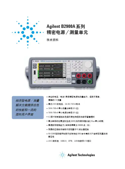
Agilent B2900A 系列精密电源/测量单元技术资料经济型电源/测量解决方案提供出色的性能和一流的图形用户界面●综合的电压/电流4 象限精密电源和测量能力,适用于简单、精确的I/V 测量●高达210 V 的电压,3 A DC/10.5 A 脉冲●10 fA/100 nV 最小测量分辨率(6½ 位)●10 fA/100 nV 最小电源分辨率(6½ 位)●4.3 英寸的前面板彩色显示屏支持图形和数字查看模式●高分辨率的任意波形生成(AWG) 和列表扫描功能(10 µs 最小间隔)●高速数字转换能力( 采样率最高为100000 点/秒)●免费的应用软件有助于实现基于PC 的仪器控制●IVI-COM 驱动程序和用于支持传统SMU 命令集的SCPI 能够实现基本的兼容性●LXI C 类标准、USB2.0、GPIB、LAN 和数字I/O 接口Agilent B2900A 系列精密电源/测量单元是外观紧凑、成本经济的台式电源/测量单元(SMU),能够同时输出并测量电压和电流。
SMU 在单个仪器中整合了电流源、电压源、电流表、电压表以及在这些功能之间自由切换的能力。
Agilent B2900A 系列SMU 以前所未有的低价格提供一流的性能。
它拥有广泛的电压(210 V) 和电流(3 A 直流和10.5 A 脉冲) 电源能力,卓越的精度( 低至10 fA/100 nV 的电源和测量分辨率) 和高测量吞吐率。
它还支持任意波形生成功能。
此外,Agilent B2900A 系列具备出色的图形用户界面及各种查看模式,可显著改进测试生产率、调试和表征过程。
Agilent B2900 系列SMU 凭借其全面、综合的电源和测量能力,成为测试半导体、有源/无源器件以及各种其他器件与材料的理想选择。
B2900 系列广泛应用在用于工业开发、测试和制造业等领域的研发和教育应用。
它们还可作为独立仪器或系统元器件使用。

e-mail: info @ For latest product manuals: User’s GuideShop online at SMFPR300FPR310FPR300/310 SERIESLow-Flow Meter***********************Servicing North America:U.S.A. Omega Engineering, Inc.Headquarters: Toll-Free: 1-800-826-6342 (USA & Canada only)Customer Service: 1-800-622-2378 (USA & Canada only)Engineering Service: 1-800-872-9436 (USA & Canada only)Tel: (203) 359-1660 Fax: (203) 359-7700e-mail:**************For Other Locations Visit /worldwideThe information contained in this document is believed to be correct, but OMEGA accepts no liability for any errors it contains, and reserves the right to alter specifications without notice.TABLE OF CONTENTS FPR300/310 SERIES INSTRUCTIONS General InformationGeneral Information ...................................................................................................................................................Page 4Features ..........................................................................................................................................................................Page 4Specifications ................................................................................................................................................................Page 5Dimensions ....................................................................................................................................................................Page 5Flow Range .....................................................................................................................................................................Page 5Pressure Drop Curve ...................................................................................................................................................Page 5 Installation & ConnectionsPiping Requirements ..................................................................................................................................................Page 6K-Factor ...........................................................................................................................................................................Page 6Connections to Control Devices ............................................................................................................................Page 6RepairRotor Replacement .....................................................................................................................................................Page 7Sensor Replacement ...................................................................................................................................................Page 7FPR300/310 Parts List ................................................................................................................................................Page 8 TroubleshootingProblem ...........................................................................................................................................................................Page 9Probably Causes ...........................................................................................................................................................Page 9Things to Try ..................................................................................................................................................................Page 9Page 3 GENERAL INFORMATION These versatile impeller flowmeters are available in 3/8”, 1/2”, 3/4”, and 1” nominal pipe sizes with female NPT threads. They employ jewel bearings to allow for very low minimum flow rates and superior life.The FPR300, with a body of polypropylene, is an economical choice for metering water or low corrosion fluids. The lens cover is available in a choice of materials: acrylic for visual flow indication of low-corrosion fluids; polypropylene when more corrosion resistance is needed. The standard rotor assembly is PVDF with tungsten carbide shaft. The O-ring is EPDM.The FPR310 offers greater chemical resistance with a PTFE body and cover, PTFE-coated FKM O-ring, and standard PVDF/ceramic rotor assembly.The pulse output of these meters is compatible with manydifferent types of controls, including a full range of Omega rate displays and controls. The Omega DPF-143 and DPF-144 provide flow rate and total flow indication. The DPF-144 also includes 4-20 mA output capability. The FMG-1000-MAW may be used for blind 4-20 mA transmission.FeaturesFPR300/310 SERIES INSTRUCTIONSPage 4FPR300Thread-in Sensor, Field Replaceable,6–24 Vdc Pulse18’ Sensor CableStandard Acrylic Top with Clear Removable Lens Assembly without clear lens)Polyproylene BodyFemale NPT PortsHex Screws Internal• Jewel Bearings—Ruby Ring and Ball• PVDF/Tungsten Carbide Rotor Assembly (PVDF/Ceramic or PVDF/Silicon Carbide optional)• EPDM O-Ring (FKM or PTFE-coated FKM optional)Thread-in Sensor, Field Replaceable,6–24 Vdc Pulse18’ Sensor CablePTFE Body and Top Female NPT PortsScrews with Hex Nuts Internal• Jewel Bearings—Ruby Ring and Ball• PVDF/Ceramic Rotor Assembly (PVDF/Silicon Carbide optional)• PTFE-coated FKM O-Ring (FKM or EPDM optional)FPR310GENERAL INFORMATION*NOTE:FPR310 cover screws are not recessedDimensionsSpecifications*FPR300FPR310Connection Ports 3/8”, 1/2”, 3/4”, 1” —Female NPT thread3/8”, 1/2”, 3/4”, 1” —Female NPT threadSensor Cable 18 ft (6 m) standard—maximum cable run 2000 ft (607 m)18 ft (6 m) standard—maximum cable run 2000 ft (607 m)MaterialsBody PolypropylenePTFERotor PVDF—2 magnet(6 magnet high resolution optional)PVDF—2 magnet(6 magnet high resolution optional)Shaft Nickel tungsten carbide(ceramic or silicon carbide optional)Zirconia ceramic(silicon carbide optional)O-Ring EDPM (FKM or PTFE-coated FKM optional)PTFE-coated FKM (FKM or EDPM optional)Bearings Ruby ring and ballRuby ring and ball CoverAcrylic with clear lens(polypropylene without clear lens optional)PTFE Maximum Temperature 160˚ F (70˚ C)180˚ F (82˚ C)Maximum Pressure 150 psi (10 bar)150 psi (10 bar)Accuracy ±1% of full scale ±1% of full scale Power 6–36 Vdc, 2 mA min.6–36 Vdc, 2 mA min.OutputsCurrent sinking pulse, 6–24 VdcCurrent sinking pulse, 6–24 Vdc* Specifications subject to change. Please consult our website for current data ()Model #NPT Thread Size-0383/8”-0501/2”-0753/4”-1001”P r e s s u r e D r o p (P S I )Flow (GPM)0510152025303551015203/8"1/2"3/4"1"Model #K-Factor* (pulses/gal)Gal/Min Liter/Min FPR310FPR300-038139414170.07–50.27–18.9-0506346580.1–100.38–37.9-0754764680.2–200.75–75-1002502540.5–401.9–150*Nominal K-factors (based on averages) for standard 2-magnet FPR310 and FPR300. High resolution (6-magnet) K-factors are approximately tripled.Flow RangePressure Drop CurvesFPR300/310 SERIES INSTRUCTIONSPage 5 INSTALLATION Piping RequirementsStandard fittings are female NPT. If the piping connected to the meter is metallic, care should be taken not to overtighten. Straight pipe of at least five diameters upstream of the meter is recommended. Vertical or horizontal installations are acceptable.K-FactorThe meter is factory calibrated. The K-factor is found on the label on the meter body and must be input into the control/display for accurate reading.K-factor on labelINSTALLATION & CONNECTIONS CONNECTIONSConnecting to Control DevicesIt is often desirable to connect an FPR300/310 flow sensor to a PLC or industrial computer board, and the sensors are well suited for this. Typically it can be connected directly, or with a single resistor added. The pickup sensors are current sinking (NPN) GMR devices that require 6–36 Volts DC and 2 mA current. They can connect directly to a PLC or computer board if:1. The sensor power supply on the PLC is 6–36 Vdc (24Vdc is typical).2. The sensor power supply can provide at least 2 mA(100 mA is typical).3. The sensor input on the PLC can accept a currentsinking device.4. The PLC frequency response > flow meter outputInput designed for current sinking devices (NPN)If the PLC input only accepts current sourcing devices, a pull-up resistor must be added. Typically, on a 24 Vdc input a 2.2 K Ohm resistor will be effective. Input designed for current sourcing (PNP) devices Since the three-wire pickup sensors are solid state, they do not exhibit switch bounce and can be used at relatively high frequencies.If the PLC is equipped with a 4-20 mA analog input module, it is necessary to order the FPR300/310 Series flow sensor with some form of 4-20 mA transmitter. Two options are the FMG-1000-MAW blind transmitter and the DPF144 indicating transmitter. Follow the connection diagrams for these products to connect to the analog input.Sinking (NPN) Devices NPN DeviceNPNDeviceSourcing (PNP) DevicesNPNDeviceNPN DeviceFPR300/310 SERIES INSTRUCTIONSPage 6REPAIRRotor ReplacementThere is only one moving part to this meter. The bearings are made of ruby, which rarely wears out or needs replacement unless they have been physically damaged by severe shock. The shaft is integrally molded into the rotor, and shaft and rotor are replaced as one part. (You may wish to replace the bearings, using the bearing removal tool, while the meter is disassembled for rotor replacement). To replace the rotor, disconnect the meter and remove the four screws that hold the cover in place. Lift the cover and remove the rotor (see parts diagram below).When putting in the new rotor, be sure that the ends of the shaft are in both bearings before tightening the cover. The rotor can be easily dropped into the bottom bearing. Starting the shaft into the upper bearing requires a bit of care. It is easier if the rotor is spinning, which can be done by lightly blowing into a port. When the upper bearing plate drops into place, hold it down and check for free spinning (by blowing lightly) before replacing the cover. Check that the O-ring is in its seat on the bearing plate before replacing the cover. Replace the cover, insert the four cap screws and tighten.Sensor ReplacementThe sensor ordinarily does not need replacement unless it is electrically damaged. If replacement is necessary, unscrew the sensor by hand. Screw the replacement sensor in and tighten by hand.Reconnect the sensor according to the diagram below.FPR300/310 SERIES INSTRUCTIONSPage 7 REPAIRFPR300/310 Parts List218345367FPR300FPR3101Body-038100221100269-050100222100268-075100223100267-1001002241002662Flow direction Label1002561002563Bearing Assembly (includes 2)103313103313Bearing Removal Tool (not shown)1003721003724Rotor with ShaftPVDF/Ceramic (2 magnet)103930103930PVDF/Carbide (2 magnet)103931n/a PVDF/Silicon Carbide (2 magnet)103933103933PVDF/Ceramic (6 magnet, high res)100453100453PVDF/Carbide (6 magnet, high res)103932n/a PVDF/Silicon Carbide (6 magnet, high res)1039341039345O- RingEPDM 100264 (standard)100264 (optional)FKM100219 (optional)100219 (optional)PTFE-coated FKM100973 (optional)100973 (standard)6Cover (after 5/2005)Polypro 100849Not available Acrylic 100848Not available PTFENot available 1008477Cover Screws (4 required)Hexscrew100310Not applicableScrew (requires hex nut 100025) Not applicable 100022Hex nut (requires screw 100022)Not applicable1000258Sensor100419100419FPR300/310 SERIES INSTRUCTIONSPage 8 TROUBLESHOOTING FPR300/310 SERIES INSTRUCTIONSPage 9FPR300/310 SERIES INSTRUCTIONS Page 10 OMEGA’s policy is to make running changes, not model changes, whenever an improvement is possible. This affords our customers the latest in technology and engineering.OMEGA is a registered trademark of OMEGA ENGINEERING, INC.© Copyright 2016 OMEGA ENGINEERING, INC. All rights reserved. T his document may not be copied, photocopied, reproduced, translated, or reduced to any electronic medium or machine-readable form, in whole or in part, without the prior written consent of OMEGA ENGINEERING, INC.FOR WARRANTY RETURNS, please have the following information available BEFORE contacting OMEGA:1. P urchase Order number under which the product was PURCHASED,2. M odel and serial number of the product under warranty, and3. Repair instructions and/or specific problems relative to the product.FOR NON-WARRANTY REPAIRS, consult OMEGA for current repair charges. Have the following information available BEFORE contacting OMEGA:1. Purchase Order number to cover the COST of the repair,2. Model and serial number of the product, and 3. Repair instructions and/or specific problems relative to the product.RETURN REQUESTS/INQUIRIESDirect all warranty and repair requests/inquiries to the OMEGA Customer Service Department. BEFORE RET URNING ANY PRODUCT (S) T O OMEGA, PURCHASER MUST OBT AIN AN AUT HORIZED RET URN (AR) NUMBER FROM OMEGA’S CUST OMER SERVICE DEPART MENT (IN ORDER T O AVOID PROCESSING DELAYS). The assigned AR number should then be marked on the outside of the return package and on any correspondence.The purchaser is responsible for shipping charges, freight, insurance and proper packaging to prevent breakage in transit.WARRANTY/DISCLAIMEROMEGA ENGINEERING, INC. warrants this unit to be free of defects in materials and workmanship for a period of 13 months from date of purchase. OMEGA’s WARRANTY adds an additional one (1) month grace period to the normal one (1) year product warranty to cover handling and shipping time. This ensures that OMEGA’s customers receive maximum coverage on each product.If the unit malfunctions, it must be returned to the factory for evaluation. OMEGA’s Customer Service Department will issue an Authorized Return (AR) number immediately upon phone or written request. Upon examination by OMEGA, if the unit is found to be defective, it will be repaired or replaced at no charge. OMEGA’s WARRANT Y does not apply to defects resulting from any action of the purchaser, including but not limited to mishandling, improper interfacing, operation outside of design limits, improper repair, or unauthorized modification. T his WARRANT Y is VOID if the unit shows evidence of having been tampered with or shows evidence of having been damaged as a result of excessive corrosion; or current, heat, moisture or vibration; improper specification; misapplication; misuse or other operating conditions outside of OMEGA’s control. Components in which wear is not warranted, include but are not limited to contact points, fuses, and triacs.OMEGA is pleased to offer suggestions on the use of its various products. However, OMEGA neither assumes responsibility for any omissions or errors nor assumes liability for any damages that result from the use of its products in accordance with information provided by OMEGA, either verbal or written. OMEGA warrants only that the parts manufactured by the company will be as specified and free of defects. OMEGA MAKES NO OTHER WARRANTIES OR REPRESENTATIONS OF ANY KIND WHATSOEVER, EXPRESSED OR IMPLIED, EXCEPT THAT OF TITLE, AND ALL IMPLIED W ARRANTIES INCLUDING ANY W ARRANTY OF MERCHANTABILITY AND FITNESS FOR A PARTICULAR PURPOSE ARE HEREBY DISCLAIMED. LIMITATION OF LIABILITY: The remedies of purchaser set forth herein are exclusive, and the total liability of OMEGA with respect to this order, whether based on contract, warranty, negligence, indemnification, strict liability or otherwise, shall not exceed the purchase price of the component upon which liability is based. In no event shall OMEGA be liable for consequential, incidental or special damages.CONDITIONS: Equipment sold by OMEGA is not intended to be used, nor shall it be used: (1) as a “Basic Component” under 10 CFR 21 (NRC), used in or with any nuclear installation or activity; or (2) in medical applications or used on humans. Should any Product(s) be used in or with any nuclear installation or activity, medical application, used on humans, or misused in any way, OMEGA assumes no responsibility as set forth in our basic WARRANTY /DISCLAIMER language, and, additionally, purchaser will indemnify OMEGA and hold OMEGA harmless from any liability or damage whatsoever arising out of the use of theProduct(s) in such a manner.Where Do I Find Everything I Need forProcess Measurement and Control?OMEGA…Of Course!Shop online at SMTEMPERATUREM U Thermocouple, RTD & Thermistor Probes, Connectors, Panels & AssembliesM U Wire: Thermocouple, RTD & ThermistorM U Calibrators & Ice Point ReferencesM U Recorders, Controllers & Process MonitorsM U Infrared PyrometersPRESSURE, STRAIN AND FORCEM U Transducers & Strain GagesM U Load Cells & Pressure GagesM U Displacement TransducersM U Instrumentation & AccessoriesFLOW/LEVELM U Rotameters, Gas Mass Flowmeters & Flow ComputersM U Air Velocity IndicatorsM U Turbine/Paddlewheel SystemsM U Totalizers & Batch ControllerspH/CONDUCTIVITYM U pH Electrodes, Testers & AccessoriesM U Benchtop/Laboratory MetersM U Controllers, Calibrators, Simulators & PumpsM U Industrial pH & Conductivity EquipmentDATA ACQUISITIONM U Communications-Based Acquisition SystemsM U Data Logging SystemsM U Wireless Sensors, Transmitters, & ReceiversM U Signal ConditionersM U Data Acquisition SoftwareHEATERSM U Heating CableM U Cartridge & Strip HeatersM U Immersion & Band HeatersM U Flexible HeatersM U Laboratory HeatersENVIRONMENTALMONITORING AND CONTROLM U Metering & Control InstrumentationM U RefractometersM U Pumps & TubingM U Air, Soil & Water MonitorsM U Industrial Water & Wastewater TreatmentM U pH, Conductivity & Dissolved Oxygen InstrumentsLT-14468r2.0 20170112M-4172/0117 1/12/17。
WDZ-900电能板原理及调试说明一、计量原理该电能板采用三相三线制计算功率,电能是该实时功率对时间的积分。
功率计算公式如下:P=P1+P2=U ab I a COSФab+U cb I c COSФcbФab和Фcb分别为U ab和I a之间,U Cb和I C之间的相角。
本装置采用两片CS5460A芯片采集电量,每秒钟得到一次功率值P1、P2,然后程序中将以上的功率值对时间进行累加,即得到累积电量。
本装置每度电所发出的脉冲个数设定为6400个。
程序将每秒钟所得到的功率值P用如下公式折算成脉冲数COUNT:COUNT = P/3600/1000*6400 ;若COUNT不足一个脉冲,则将P保存与下一次的功率采样值累计;若COUNT真整数值大于等于一个脉冲,则将COUNT的整数脉冲数发出,余下的相应电量保存与下一次的功率采样值累计,因此本装置的脉冲不是完全等间隔的。
二、软件版本说明1.R400-PM-51-v200该软件适用于输入的电流满度值为5A,相电压为57.74V;电能为两位小数。
2.R400-PM-11-v200该软件适用于输入的电流满度值为1A,相电压为57.74V;电能为两位小数。
3.R400-PM-54-v200该软件适用于输入的电流满度值为5A,相电压为220V;电能为两位小数。
三、显示值说明在WDZ-400型装置的主菜单→测量显示→电能板电能菜单下,相关项目如下:PEM――每分钟有功电能的累计值,单位(瓦×秒);PES――每秒钟的有功功率值,单位(瓦);PE ――有功电能的总累计值,单位(千瓦×时);QEM――每分钟无功电能的累计值,单位(乏×秒);QES――每秒钟的无功功率值,单位(乏);QE ――无功电能的总累计值,单位(千乏×时);其中PEM、QEM需在装置上电第二分钟后的刷新值,才是有效值。
四、出厂校准方法i.电能板调试进入电能板调试画面的路径:主菜单→调试操作→电能板调试a:电能增益调整(1) 若软件为R400-PM-51-v200施加电流电压Ua =Ub=Uc=57.7V,φua=0°、φub=240°、φuc=120°,MIa =MIc=5A,φia=30°、φic=90°按确认键后进入主菜单→通讯监测→电能板监测→MSG_RX,若该值有变化说明电能增益校准完毕。
Keysight B2961A/B2962A6 1/2 位低噪声电源1通道和 2通道210 V,3 A 直流 / 10.5 A 脉冲,31.8W100 nV / 10 fA 分辨率技术资料惊人的 6 1/2位 100 nV/10 fA 分辨率、10 μVrms 超低噪声和创新的电源功能,加速您的研发进程创新的电源可满足当前和未来的测试需求在电子行业中的测试测量工作中,电源是必不可少的仪器。
整个行业正在向不断降低功耗和加快通信数据速率方向发展,这就需要电源能够支持更低的电流和电压。
这些需求迫使电源必须进一步提高性能。
Keysight B2961A/B2962A 6 1/2 位低噪声电源是一款全新的台式电源,具备前所未有的创新能力和功能。
它的独特性能包括:双极性电流供给和电流吸收、可编程输出电阻功能,以及图形用户界面(GUI),支持时域波形查看。
我们有 1 通道(B2961A)和 2 通道(B2962A)型号,为您的测试需求提供最恰当的台式电源性能。
–同类产品中最佳的 6 1/2 位分辨率(100 nV/10 fA 最低分辨率)–宽广的双极(四象限)电压/电流范围(210 V/3A 直流,10.5A 脉冲)–超低噪声滤波器(10 μVrm,10 kHz 时为1 nV/√ Hz )–4.3 英寸彩色 LCD 显示屏,直观的图形用户界面–使用4 1/2 位电压和电流监测仪–时域波形查看器,便于快速进行查看和调试–精密的 1 mHz 至 10 kHz 任意波形生成能力–灵活的可编程输出电阻功能。
除了这些创新的台式电源特性之外,用户还可使用在 PC 上运行的是德科技免费软件 BenchVue、Quick IV 或符合 LXI 标准的网络浏览器对 Keysight B2961A/B2962A 进行远程控制。
这些功能使得将测量数据和图形合并到报告和演示中的任务变得轻松无比。
Keysight B2961A/B2962A 的卓越性能和创新功能适用于广泛的测试应用。
ZRR-900B系列保护测控装置技术及使用说明书南京振瑞电气有限公司2015年2月出厂默认设定:目录第一章概述 (1)1.1产品适用范围 (1)1.2产品特点 (1)1.3产品分类 (2)第二章主要参数和技术指标 (3)2.1技术参数 (3)2.2正常工作大气参数 (3)2.3绝缘性能 (4)2.4电磁兼容 (4)2.5机械性能 (5)2.6实施标准 (5)第三章装置外观及安装 (6)3.1产品外观示意图 (6)3.2外形尺寸图(单位:MM) (6)3.3开孔安装尺寸图(单位:MM) (7)第四章主要功能 (8)4.1ZRR-911B线路保护测控装置 (8)4.1.1启动元件说明 (9)4.1.2 保护功能 (9)4.1.3 定值及压板说明 (15)4.1.4 背板端子定义图 (17)4.1.5 ZRR-911B型装置工程接线示意图 (18)4.2ZRR-921B厂用变压器保护测控装置 (19)4.2.1启动元件说明 (19)4.2.2 保护功能 (19)4.2.3 定值及压板说明 (23)4.2.4 背板端子定义图 (25)4.2.5 ZRR-921B型装置工程接线示意图 (26)4.3ZRR-931B电容器保护测控装置 (27)4.3.1启动元件说明 (27)4.3.2保护功能 (27)4.3.3 定值及压板说明 (31)4.3.4 背板端子定义图 (33)4.3.5 ZRR-931B型装置工程接线示意图 (34)4.4ZRR-951B电动机保护测控装置 (35)4.4.1启动元件说明 (35)4.4.2 保护功能 (35)4.4.2 定值及压板说明 (41)4.4.3 背板端子定义图 (43)4.4.4 ZRR-951B型装置工程接线示意图 (44)4.5ZRR-961B PT保护装置 (45)4.5.1保护功能 (45)4.5.2 定值及压板说明 (46)4.5.3 背板端子定义图 (47)4.5.4 ZRR-961B型装置工程接线示意 (48)第五章操作使用说明 (49)5.1信号灯说明 (49)5.2按键说明 (49)5.3液晶显示说明 (50)5.3.1正常运行显示 (50)5.3.2动作报告显示 (50)5.4菜单使用说明 (51)5.4.1 刻度显示 (51)5.4.2 开入显示 (52)5.4.3 开出检测 (52)5.4.4事故追忆 (53)5.4.5保护定值 (54)5.4.6压板设置 (55)5.4.7参数设置 (55)5.4.8版本信息 (57)第六章常见故障及解决方法 (58)第一章概述1.1产品适用范围ZRR-900B系列保护测控装置是我公司推出的全系列配电系统智能化控制产品,它基于高性能DSP处理器硬件平台和嵌入式实时操作系统,集保护、控制、通讯、测量、监视功能于一身,是智能化、网络化、数字化的低压配电控制产品。
Samsung ER-920 ER-925 ER-940 ER-945 Operation and programming ManualContentsIntroduction 11 About the ER-900 Series (11)Using This Manual (12)Using Flowcharts (12)Basic Features and Functions (13)Display (14)Printer/Printers (15)Control Lock (16)Keyboards (17)Initial Clear (19)Getting Started 21 Quick Start Steps (21)Unpacking (22)Installing the Paper (22)Models with Two Printer Stations (23)Clearing Memory (26)ER-920/ER-940 Memory All Clear (26)ER-925/ER-945 Memory All Clear (27)Straight Percentage Tax Rate Programming (29)Programming Tax & Preset Status for Keyboard PLUs (30)Programming a Price for a Preset Keyboard PLU (31)Programming a Descriptor for Keyboard PLUs (32)Operations 35 Function Key Descriptions (35)Clerk Sign-On/Sign-Off (41)Direct Sign-On (41)Coded Sign-On (42)Receipt On and Off (42)PLU Registrations (43)Keyboard PLU Entries (43)Numeric PLU Entries (46)Modifier Entries (48)Percentage Key (%) Registrations (49)Void and Correction Operations (52)Error Correct (52)Previous Item Void (53)Merchandise Return (54)VOID Control Lock Position (Transaction Void) (55)Cancel (56)Subtotal Operations (57)Subtotal (57)SAM4s ER-900 Series Operator's & Programming Manual v.1.7 Introduction • 5Add Check (Tray Subtotal) (57)Eat-In/Take-Out/Drive Thru Operations (58)Tax Shift Operations (59)Tendering Operations (61)Cash (61)Check (61)Charge (62)Split Tender (63)Post Tendering (63)Receipt on Request (64)Training Mode (64)Clerk Interrupt (64)Non-Add Number (65)No Sale (65)Received on Account (66)Paid Out (66)Table Service Restaurant Operations (67)Overview (67)Posting Guest Checks Manually with the Previous Balance Key (69)Soft Check (70)Hard Check (73)Fast Food Drive Thru (76)Promo Function (77)Waste Function (77)Charge Posting Operations (78)Currency Conversion (81)Food Stamp Operations (82)Scale Operations (83)Direct Scale Entry (83)Manual Weight Entry (83)Scale with Automatic Tare Entry (84)Scale with Manual Tare Entry (84)Validation (85)Integrated Payment Operations (85)Not Found PLU (86)Not Found PLU: Quick Entry (86)Not Found PLU: Detail Entry (86)Not Found PLU Report (86)Management Functions 87 Introduction (87)Cash Declaration (88)System Reports (90)Running a Report – General Instructions (90)Report Table (91)S-Mode Programming 93 Overview (93)Clearing Memory (94)Memory All Clear (94)Clear All Totals and Counters (94)Clear Grand Total (94)Clear PLU File (94)6 • Introduction SAM4s ER-900 Series Operator's & Programming Manual v.1.7Self Tests (95)Memory Allocation (96)Memory Capacity (96)Memory Allocation Program (97)Memory Allocation Program Scan (98)Function Key Assignment Programming (99)Function Key Codes (100)RS-232 Communication Option Programs (101)RS-232 Option Chart (102)SD Card Utilities (104)Program Backup and Restore (104)Saving Reports to an SD Card (105)Load/Save Receipt Images (106)1. Preparing a Graphic Logo Bitmap for an ER-900 Series (106)2. Use the PC Utility to Convert the Image (107)3. Copy the Images to an SD Card (107)4. Load the Images by SD Card (108)5. Saving Images from an ER-900 to an SD Card (108)Flash ROM Updates (109)Flash ROM Update by SD (109)Flash ROM Update by PC (110)Flash ROM Information (113)P-Mode Programming 115 Default Program (115)Tax Programming (116)Straight Percentage Tax Rate Programming (117)Tax Table Programming (118)PLU Programming (120)Program 100 - PLU Status Programming (121)Program 110 - PLU Auto Tare Programming (125)Program 150 - PLU Group Assignment (126)Program 200 - PLU Price/HALO Programming (127)Program 250 - PLU Stock Amount Programming (128)Program 300 - PLU Descriptor Programming (129)Program 350 - PLU Link Programming (132)Program 400 – PLU Delete Programming (133)Program 450 – PLU Mix and Match Programming (134)System Option Programming (135)System Option Table (136)System Options - Reference Information (140)Print Option Programming (143)Print Option Table (144)Function Key Programming (150)Program 70 - Function Key Options (150)Program 80 - Function Key Descriptor (151)Program 90 - Function Key HALO (152)Instructions for Currency Conversion Rate - Program 90 (153)ADD CHECK - Function Key Options (154)CANCEL - Function Key Options (155)CASH - Function Key Options (155)CHARGE 1-8 - Function Key Options (156)CHECK - Function Key Options (157)CHECK CASHING - Function Key Options (158)SAM4s ER-900 Series Operator's & Programming Manual v.1.7 Introduction • 7CHECK ENDORSEMENT - Function Key Options (158)CHECK # - Function Key Options (159)DRIVE THRU / EAT IN / TAKE OUT - Function Key Options (160)ERROR CORRECT - Function Key Options (161)F/S Subtotal - Function Key Options (161)F/S TEND - Function Key Options (162)GUEST - Function Key Options (163)#/NS - Function Key Options (164)MDSE RETURN - Function Key Options (165)MODIFIER 1-5 - Function Key Options (166)PBAL - Function Key Options (168)PROMO - Function Key Options (168)PAID OUT 1-3 - Function Key Options (169)PRINT CHECK - Function Key Options (169)RECD ON ACCT 1-3 - Function Key Options (170)SCALE - Function Key Options (170)SERVICE - Function Key Options (171)SUBTOTAL - Function Key Options (171)TABLE - Function Key Options (172)TARE - Function Key Options (172)TAX EXEMPT - Function Key Options (173)TIP - Function Key Options (174)VALIDATE - Function Key Options (175)VOID - Function Key Options (175)WASTE - Function Key Options (176)%1-%5 Function Key Options (177)Mix and Match Discount Programming (178)Program 600 – Trip Level Programming (179)Program 601 – Price Programming (179)Program 610 – Mix & Match Descriptor Programming (180)Clerk Programming (181)Program 800 - Secret Code Programming (181)Program 801 - Drawer Assignment (182)Program 810 - Clerk Descriptor Programming (183)Group Programming (184)Miscellaneous Programming (186)Program 1500 - Macro Key Sequence Programming (186)Program 700 – Logo/Endorsement Message Programming (187)Program 701 - Financial Report Descriptor Programming (188)Program 710 - Clerk Report Descriptor Programming (190)Program 711 - Macro Name Programming (192)Program 720 – Datatran Message Program (193)Program 1000 - NLU Code Number Programming (194)Program 1100 - Cash-In-Drawer Limit Programming (195)Program 1200 - Check Change Limit Programming (196)Program 1300 - Date and Time Programming (197)Program 1400 - Scale Tare Weight Programming (198)Program 1600 - Machine Number Programming (199)Program 1900 – Starting Kitchen Printer Order Number (199)Program Scans (200)Sample Reports 201 Financial (201)Time (205)8 • Introduction SAM4s ER-900 Series Operator's & Programming Manual v.1.7PLU (206)Clerk (207)Individual Clerk (208)Groups (209)Stock (210)Open Check (211)Balancing Formulas (212)Integrated Payment Appendix 213 One Day Example of Credit Authorization (213)Open Batch (213)Sample Credit Transaction (214)Sample Debit Transaction (215)Gift Card Operations (216)Manual Card Entry (Credit/Gift Only) (218)Merchandise Return (219)Void Transaction (220)Local Total Report (220)Tip (Gratuity) Entry (220)Close Batch (221)Reset Mode Procedures (222)Datatran Function Table (222)Initialize EFT (223)Clear Curr Batch (223)Chg Batch Number (223)Issue Local Total (223)Issue Transaction (224)Issue Batch Status (224)Dial In Load/Dial Out Load (225)Pin Pad Initialize (226)DataTran Diagnostics (226)Log File Report (227)Required ECR Programs (228)Local Transaction Report Key (228)Glossary 231Manual Revision Record 239 SAM4s ER-900 Series Operator's & Programming Manual v.1.7 Introduction • 9This is a “Table of Contents preview” for quality assuranceThe full manual can be found at /estore/catalog/ We also offer free downloads, a free keyboard layout designer, cable diagrams, free help andsupport. : the biggest supplier of cash register and scale manuals on the net。
Keysight B2900A 系列精密型源表配置指南经济高效的电源和测量一体化解决方案,提供卓越的性能和一流的图形用户界面配置您的 Keysight B2900A 系列精密型源表Keysight B2900A 系列精密型源表(SMU)包含下列四个型号。
–B2901A 精密型源表,1 通道,100fA 分辨率,210V,3A 直流/10.5A 脉冲–B2902A 精密型源表,2 通道,100fA 分辨率,210V,3A 直流/10.5A 脉冲–B2911A 精密型源表,1 通道,10 fA 分辨率,210V,3A 直流/10.5A 脉冲–B2912A 精密型源表,2 通道,10 fA 分辨率,210V,3A 直流/10.5A 脉冲本配置指南提供逐步的指导,旨在帮助您配置 SMU 及其相关附件,满足您的特殊测试要求。
详细技术指标请参见 B2900A SMU 系列技术资料(5990-7009EN)。
第1步:选择 B2900A 系列型号您选择的时候首先需要考虑两个重要因素:测量通道数(一个或两个)和源表的性能。
B2900A 系列分为标配型(B2901A/B2902A)和高性能型(B2911A/B2912A)两个档次。
需要注意的是,标配的型号在购买后,无法通过升级来获得更多个通道或高性能的型号。
B2901A1210 V3.03 A 200 V10.5 A1 pA1 V100 fA100 nV20 ųs单一视图、图形视图B2902A2210 V3.03 A 200 V10.5 A1 pA1 V100 fA100 nV20 ųs单一视图、双视图、图形视图B2911A1210 V3.03 A 200 V10.5 A10 fA100 nV10 fA100 nV10 ųs单一视图、图形视图、滚动视图B2912A2210 V3.03 A 200 V10.5 A10 fA100 nV10 fA100 nV10 ųs单一视图、双视图、图形视图、滚动视图描述数量更多信息1.产品资料光盘 1 个包括用户手册电子文件、驱动程序和软件2.Keysight I/O 程序库光盘 1 个包括 Keysight I/O 程序库的驱动程序和安装软件3.快速参考 1 个印刷版快速入门指南(英文版)4.校准证书(无测试数据) 1 个校准证书(无实际测试数据)。
如果您需要测试数据,请指定选件 UK6。
B 电缆 1 个USB 电缆(1.8 米)。
可订购部件编号 8121-1696。
下面附件作为每款 B2900A 系列 SMU 的标准配置提供:第2步:添加可选且经过本地化的用户指南随 B2900A 发售的光盘中提供 PDF 文件格式的 B2900A 手册(用户指南等)。
如果您需要印刷版手册,可使用下面显示的部件编号订购。
第3步:选择可选附件第 3-1 步选择机架安装套件(可选)描述产品型号更多信息印刷版手册(用户指南),英文版B2901A-ABAB2902A-ABA B2911A-ABA B2912A-ABA 印刷版印刷版手册(用户指南),日文版B2901A-ABJ B2902A-ABJ B2911A-ABJ B2912A-ABJ 印刷版印刷版手册(用户指南),繁体中文版B2901A-AB0B2902A-AB0B2911A-AB0B2912A-AB0印刷版印刷版手册(用户指南),简体中文版B2901A-AB2B2902A-AB2B2911A-AB2B2912A-AB2印刷版从是德科技网站下载产品手册B2901A-0B0B2902A-0B0B2911A-0B0B2912A-0B0非印刷版描述产品型号更多信息机架安装套件B2901A-1CMB2902A-1CM B2911A-1CM B2912A-1CMB2900A 系列的机架安装套件2U 高 EIA 和 1/2 机架宽。
描述产品型号更多信息印刷版手册(用户指南),英文版B1540-90007印刷版,EasyEXPERT group+ 第 1 卷B1540-90021印刷版,EasyEXPERT group+ 第 1 卷印刷版手册(用户指南),日文版B1540-97007印刷版,EasyEXPERT group+ 第 2 卷B1540-97021印刷版,EasyEXPERT group+ 第 2 卷随 B2900A 发售的光盘中还提供 PDF 文件格式的 EasyEXPERT group+ 软件手册(用户指南)包括。
如果您需要印刷版手册,可使用下面显示的部件编号订购。
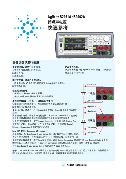
第3-2步:确定您是否需要进行4线测量和防护B2900A SMU 可支持 2 线和 4 线测量。
默认连接方案为较为简单的 2 线配置,该配置仅使用Force端接。
在 2 线模式下,感应端接保持开路。
如果您要测量非常小的电阻或要施加非常大的电流,那么您应使用 4 线测量方法(也称为 Kelvin 方法)。
这种技术同时使用Force和感应端接,通过感应端接测量(无电流经过),电缆电阻的效应能被消除。
低电流测量(< 1nA)需要增加防护,以防止通过测量电缆的电流泄露。
下面的原理图提供了有关防护技术的简要概述。
防护测量需要使用三同轴电缆。
一个(x1)随动的缓冲放大器使防护导体与中心导体处于同一电势。
由于没有压差,不会有电流从中心导体流向防护导体。
注:2 线连接 4 线连接保护技术第3-2步:确定您是否需要进行 4 线或防护测量(续)1. 无防护的 2 线连接方案2. 无防护的 4 线连接方案推荐的连接轻松连接典型连接实例11059A 简化了连接,但不支持大于 ± 42 V 的电压幅度。
推荐的附件U8201A 综合测试引线套件11059A Kelvin 成套探头推荐的连接轻松连接典型连接实例11059A 简化了连接,但不支持大于 ± 42 V 的电压幅度。
推荐的附件U8201A综合测试引线套件11059AKelvin成套探头第3-2步:确定您是否需要进行 4 线或防护测量(续)3. 带防护的 2 线连接方案推荐的连接典型连接实例N1295A 不支持大于 ± 42 V 的电压。
16442B 支持高达 200 V 的电压。
推荐的附件16494A-001 2 个低泄漏三同轴电缆( 1.5 米)16494A-0012 个低泄漏三同轴电缆(1.5 米)N1294A-001 1 个香蕉插头 – 三同轴适配器,适用于 2 线(非 Kelvin )连接N1294A-0011 个香蕉插头 – 三同轴适配器,适用于 2线(非 Kelvin )连接N1295A1 个元器件测试夹具16442B1 个通用测试夹具4. 带防护的 4 线连接方案推荐的连接典型连接实例推荐的附件16494A-001 3 个低泄漏三同轴电缆(1.5 米)N1294A-002 1 个香蕉插头 – 三同轴适配器,适用于 4 线(非 Kelvin )连接16442B1 个通用测试夹具N1294A-00216442B16494A-001第3-3步:考虑互锁电路(可选)为了防止意外暴露在危险的高电压下,B2900A SMU 拥有安全互锁。
除非互锁电路关闭,否则它们不能提供大于 ± 42 V 的电压。
这可通过使用后面数字 I/O 输出的第 16 和第 24 引脚实现。
通常,这些引脚会路由至屏蔽盒或测试夹具。
要完成互锁电路,它们必须闭合。
如果您正在使用 16442B 测试夹具,那么您可使用 N1294A-011 或 012 互锁电缆连接到互锁电路。
如果您未使用 16442B ,那么您应按下图所示安装联锁电路。
如欲了解详细信息,请参见 Keysight B2900A 系列用户指南中的“安装互锁电路”。
第3-4步:确定您是否将 B2900A 系列与多个免费软件控制选件(可选)结合使用选择最佳的解决方案。
B2900A 数字 I/O15, 19 24, 251415, 19负极 正极22, 23屏蔽盒16, 17行详细表征与分析–要通过 GPIB 接口实现软件控制,需要使用 82357B GPIB-USB 接口。
–B2900A 系列提供有 1.8 米 USB 电缆,以便通过 USB 接口实现软件控制。
–通过 LAN 接口实现软件控制需要使用 LAN 电缆。
–EasyEXPERT group+ 软件支持同步控制多个单元。
详细信息请看下页。
第3-4步:确定您是否将 B2900A 系列与多个免费软件控制选件(可选)结合使用EasyEXPERT group+ 软件能够最多同时控制4台 B2900A SMU。
当您使用 EasyEXPERT group+ 软件控制多台 B2900A SMU时,需要连接触发线,以便使一个单元和其他单元保持同步。
只有 GPIB 连接可支持 EasyEXPERT group+。
1.使用单台 B2900A SMU推荐的同步附件B2900A 1 个精密型源表82357B 1 个USB/GPIB 接口推荐的同步附件B2900A 2 个精密型源表82357B 1 个USB/GPIB 接口N1294A-032 1 个数字 I/O 触发器电缆,适用于多个单元控制10833D 1 个GPIB 电缆(0.5 米)推荐的同步附件B2900A 3 个精密型源表82357B 1 个USB/GPIB 接口N1294A-032 1 个数字 I/O 触发器电缆,适用于多个单元控制10833D 2 个GPIB 电缆(0.5 米)2.使用 2台 B2900A SMU3.使用3台 B2900A SMU第3-4步: 确定您是否使用配备 EasyEXPERT group+ 软件的 B2900A SMU (续)EasyEXPERT group+ 软件能够最多同时控制4台 B2900A SMU 。
当您使用 EasyEXPERT group+ 软件操作多台 B2900A SMU 时,需要连接触发线,以便使任何一台于其他几台保持同步。
只有 GPIB 连接可支持 EasyEXPERT group+。
4. 使用4台 B2900A SMU第3-5步: 选择其他附件(可选)针对特定要求,可选择下列可选附件。
推荐的同步附件B2900A 4 个精密型源表82357B 1 个USB/GPIB 接口N1294A-032 1 个数字 I/O 触发器电缆,适用于多个单元控制10833D3 个GPIB 电缆(0.5 米)描述产品型号更多信息低泄漏三同轴电缆(1.5 米)16494A-00116494A 三同轴电缆支持高达 200 V 电压和 1 A 电流。
低泄漏三同轴电缆(3.0 米)16494A-002低泄漏三同轴电缆(0.8 米)16494A-003低泄漏三同轴电缆(0.4 米)16494A-004低泄漏三同轴电缆(4.0 米)16494A-005高电流三同轴电缆(1.5 米)16493L-00116493L 三同轴电缆支持高于 1 A 的电流。