RMH公司及产品介绍-2015.6.3
- 格式:pdf
- 大小:3.67 MB
- 文档页数:76

RM800对比敏感度产品介绍温州雷蒙光电科技有限公司一:仪器概述:R M800对比敏感度仪,用于检测不同对比度下的视觉分辨率。
本仪器针对:1:传统的视力检查,是用黑白分明的视标(视力表)来检查视觉分辨率,无法测量视觉对于不同对比度的分辨能力。
2:眼科临床上希望能对组成视觉系统的屈光部分和视网膜到大脑信息处理系统部分的功能,分段做出单独测定和评价,但视力表所测得的是整个视觉系统的视力。
3:避免采用激光作为光源来测试人眼的对比敏感度。
RM800对比敏感度仪把对比度传递函数引入视觉系统,以此来对人眼的成像质量进行检查和评价。
本仪器由光学系统,机械结构,电子线路以及单片电子计算机组成。
是光机电一体化的新型视功能检查仪器,仪器通过计算机人机界面进行操作,实现了自动检查模式。
同时它能将视觉功能的信息,进行储存和处理,同时还可以通过网络进行远程会诊。
是视光学医疗技术的信息化项目。
仪器采用空间光栅产生衍射条纹作为视标,通过改变条纹的空间频率,对比度以及方向来检查视功能。
同时,仪器还具有单独检查视网膜的功能,可以实现对全视系统进行分段检查。
二:主要功能介绍1:测定人眼视觉系统的对比敏感度(CS)。
2:测定视网膜的对比敏感度。
3:测定白内障患者干涉条纹视力(IVA),即视网膜视力。
4:测定眩光对比敏感度(GS)。
5:测定IVA-CS曲线。
三:主要临床应用:1:测试人眼在不同亮度和对比度情况下的视觉分辨率,广泛应用于准分子激光手术效果评估。
2:可实现分段检查,即视网膜到大脑段的视力(视网膜视力)以及对比敏感度,对于白内障患者,可预测做完白内障手术后效果。
同时避免由于视网膜到大脑的问题,做完白内障手术后效果不理想,而产生的医疗纠纷。
3:IVA-CS曲线对于青光眼,黄斑疾病,糖尿病性视网膜病变,视神经疾病、弱视等非常敏感。
对于早期提示有很重要的实用价值。
4:对于白内障,激光屈光手术的术前、术后视功能检查,都有十分重要的价值。

氟致冷剂氟致冷剂,又称氟里昂,是某些氟氯代烷的统称,它是一种无色无臭的液化气,无毒、不燃,被广泛用于制冷、塑料、化妆品、医药等工业,作为致冷剂,发泡剂和气雾剂。
我公司是国内氟致冷剂最大的生产厂家之一,F12、F22是浙江省优质产品。
F12分子式:CCl2F2沸点:-29.8规格:GB7372-87指标名称一级品合格品外观无色、不浑浊气味无异臭纯度,%(m/m) 99.5 99.0水份,%(m/m) 0.001 0.003酸度(以HCL计),%(m/m) 0.0001 0.0001蒸发残留液,%(m/m) 0.01 0.02用途:广泛用作致冷剂、发泡剂和气雾剂。
包装规格:钢瓶包装。
每瓶净重5kg, 13.5kg, 22.7kg, 40kg, 450kg, 900kg。
F22分子式:CHClF2沸点:-40.8规格:GB7373-87指标名称一级品合格品外观无色、不浑浊气味无异臭纯度,%(m/m) 99.5 99.0水份,%(m/m) 0.002 0.005酸度(以HCl计),%(m/m) 0.0001 0.0001蒸发残留物,%(m/m) 0.01 0.02用途:广泛用于空调行业和化学工业,用作致冷剂以及卤代烷灭火剂和聚四氟乙烯的中间原料。
包装规格:钢瓶包装。
每瓶净重13.5kg,22.7kg,40kg,400kg,800kg。
CFC替代品70年代初,环境科学家发现氯氟烷烃(CFC)对大气臭氧层有破坏作用,因而对人类的生存环境构成严重威胁。
因此CFC替代品的开发和使用成为不可逆转的潮流。
我公司目前可提供CFC替代品品种如下:CFC替代品规格表品名沸点()被替代品包装规格(kg) ODPHFC-134a -26.5 CFC-12 40,420 0R500 -33.5 CFC-12 13.6,22.7 0.7R502 -45.4 CFC-12 13.6,22.7 0.18R32 -53.15 R22 13.6,22.7 0R152a -24.7 CFC-12 13.6,22.7 0R141b 32.05 R11、R113 13.6,22.7,420 0.15R142b -9.2 用作高温下致冷 13.6,22.7,420 0.06R123 27.85 R11、R113 13.6,22.7 0.02R124 -10.95 R502、R22 13.6,22.7 0.02R125 -48.45 R502、R22 13.6,22.7 0R23 -80.05 CFC-13 40 0R407c -43.7 R22 420,800 0。
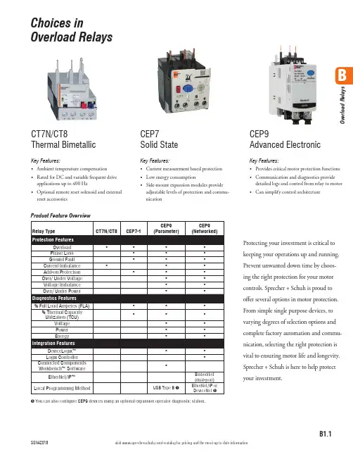
B1.1visit /ecatalog for pricing and the most up to date informationBO v e r l o a d R e l a y sProduct Feature Overview➊ You can also configure CEP9 devices using an optional expansion operator diagnostic station.Choices inOverload RelaysProtecting your investment is critical to keeping your operations up and running. Prevent unwanted down time by choos-ing the right protection for your motor controls. Sprecher + Schuh is proud to offer several options in motor protection. From simple single purpose devices, to varying degrees of selection options and complete factory automation and commu-nication, selecting the right protection is vital to ensuring motor life and longevity. Sprecher + Schuh is here to help protectyour investment.CT7N/CT8Thermal BimetallicKey Features:• Ambient temperature compensation • Rated for DC and variable frequent drive applications up to 400 Hz • Optional remote reset solenoid and external reset accessoriesCEP7 Solid StateKey Features:• Current measurement based protection • Low energy consumption• Side-mount expansion modules provide adjustable levels of protection and commu-nicationCEP9Advanced ElectronicKey Features:• Provides critical motor protection functions • Communication and diagnostics provide detailed logs and control from relay to motor • Can simplify control architecture3r d G e n C E P 7 O v e r l o a d sB1.2visit /ecatalog for pricing and the most up to date informationCEP7 Solid State Overload RelaysThe Third GenerationAdvanced solid state motor protectionThe CEP7-1__ relay provides the follow-ing features:• Electronic overload detection • Simple configuration • Selectable trip class • Adjustable trip current• Integration with CA7/CAN7 contactors• Test and reset buttons• Auto (CEP7-1EF only)/manual resetselection• RMS current sensing (50/60 Hz)• External current transformer configu-rations • Single- and Three-phase compatibility within the same unit • Direct and pass-through mounting options The CEP7-1__ relay lets you connectaccessory modules, some of which inter-face through the front-mounted com-munication port. Accessories include:• Ground fault/jam protection module(CEP7-1EF only)• Remote reset solenoid• Anti-tamper shield• Electronic remote indication display CEP7–ERID, with or without reset (CEP7–1EF units only)• External reset adapter • DIN rail/Panel adapterOverload Performance• Current Measurement-based Protection Current measurement-based overload protection more accurately models amotor’s thermal condition. Ambient temperature over the specified temperature operating range does notimpact the performance of current measurement-based designs.• Electronic Design Thermal model-ing is performed electronically withprecision solid-state components, us-ing a state-of-the-art microprocessor.The microprocessor continually pro-cesses motor current data to accurately maintain the time-current status of the motor thermal capacity utilization (%TCU) value.• Thermal Memory A thermal mem-ory design lets the CEP7-1 OverloadRelay model the heating and cooling effects of motor on and off periods. This achieves accurate protection for both hot and cold operation.• Phase Loss Protection Phase loss detection is incorporated into the CEP7-1 Overload Relay, allowing it to respond quickly to this type ofcondition.Direct Mount Mechanicalattachment800A100A 100A 100A3r d G e n C E P 7 O v e r l o a d sB1.3visit /ecatalog for pricing and the most up to date informationVersatile and Expandable• Adjustable Trip Class and Reset Modes The Basic CEP7-1EE relay of-fers Trip Class 10 and 20 with manual reset only. The Advanced CEP7-1EF relay offers Trip Class 10, 15, 20, and 30 with a selectable dial, in manual or automatic reset.• Pass-through Design The CEP7-1 relay Pass-through option consumes less panel space than a standard CEP7-1 relay that is configured with a panel-mount adapter. The pass-through design provides integrated DIN Rail mount and panel mount-ing holes. The CEP7-1 Pass-through Electronic Overload Relay provides the same protection and expandable accessory capabilities as a standard CEP7-1 relay.• External CTs For motor overload protection applications above 100A in current sensing capability, the CEP7–1EF_Z relay offers functionality with external CT configurations up to 800A maximum capacity.Wide current adjustment rangeThermal or bimetallic overload relays typically have a small current adjust-ment range of 1.5:1 meaning that the maximum setting is generally 1.5 times the lower setting. Sprecher + Schuh’s CEP7-1 overload relay is capable of adjustment to a maximum of five times the minimum set current, which dra-matically reduces the number of units required on-hand to cover the full range of current settings up to 100 amperes.Selectable tripping classBoth the CEP7-1 models have standard Class 10 tripping characteristics. The CEP7-1EE Basic model is equipped with dip switches that allow the select ability between Class 10 and Class 20, while the CEP7-1EF Advanced model possesses a selection dial on the face of the overload for trip classes 10/15/20 and 30. This selection feature allows you to closely match the Trip Class with the start-up time of the motor.Adaptive ProtectionRemote Reset CapabilityThe CEP7-1EF relay offers optional remote reset capabilities through the use of an electro-mechanical reset solenoid or an electronic remote reset accessory module.Ground Fault and Jam Protection The CEP7-1EF relay offers optional ground fault and jam protectionthrough the use of an accessory module. The ground fault current detection level is configurable via a mechanical rotary dial from 0.02…5A. Jam protection is configurable via two mechanical rotary dials, current level from 125…600% FLA, and delay from 0.1…10 seconds.Robust designThe CEP7 has been designed to physi-cally extend to the back-pan therefore aligning the mounting of the overload with the corresponding contactor. Further, the mechanical attachment and direct electrical connection to the contactor provides a robust mounting, which means less damage from shipping or during field wire installation. The bipolar latching relay which controls the normally closed trip contacts and nor-mally open alarm circuit contacts have been self-enclosed, therefore insulating the electromagnet and shielding against airborne metal particles and other po-tential environmental debris. The CEP7 has been tested to operate in -20° C. or up to 60° C (140 °F.) and withstand 3G of vibration or 30G of shock on a mountain up to an altitude of 2000m or in a jungle at 95% humidity. Reliability under every conceivable environmen-tal condition is a quality built into the design of the CEP7 electronic overload relay.Increased accuracy and improved motor protectionMicroelectronics provide flexible and ac-curate motor overload protection. Unlike traditional overload relays that simulate heat build-up in the motor by passing current through a heater element, CEP7 solid state overload relays measure motor current directly through integrated cur-rent transformers. The transformers, in turn, create a magnetic field that induces DC voltage onto the ASIC board. The electronics identify excessive current or loss of phase more accurately, and react to the condition with greater speed and reliability than traditional overload re-lays. In addition, CEP7 solid state relays offer setting accuracies from 2.5 – 5% and repeat accuracy of 1%.Dramatically lowered energy requirement saves money, reduces panel spaceBecause traditional overload relays work on the principle of “modeling” the heat generated in the motor (recreating the heat in the bimetal elements or heaters), a significant amount of energy is wasted. In traditional bimetallic overload relays, as many as six watts of heat are dissipat-ed to perform the protective function. Because the CEP7 uses sampling tech-niques to actually measure the current flowing in the circuit, very little heat is dissipated in the device…as little as 0.5 watts. This not only reduces the total amount of electrical energy consumed in an application, but it can also have a dra-matic impact on the design and layout of control panels. The density of motor starters can be much greater because less heat is generated by each of the individ-ual components. Higher density results in smaller control panels. In addition, special ventilation or air conditioning that might have been required to protect sensitive electronic equipment such as PLC’s can now be reduced or eliminat-ed. CEP7 overload relays dramatically reduced energy requirement saves moneyand reduces panel space.CEP7-1EF Selectable Dial for • Manual vs. automatic• Trip class 10, 15, 20 or 30)CEP7-1EE SwitchSelection for Trip class (10 or 20)3r d G e n C E P 7 O v e r l o a d sB1.4visit /ecatalog for pricing and the most up to date information➊ This reference is not intended to be a guide for selecting contactors. Size overload relays using the full load current of the motor.➋ The reset time of a CEP7 set in the automatic mode is approximately 120 seconds.➌ CEP7 overload relays do not work with Variable Frequency Drives, DC Applications or Softstarters with braking options.shown: CEP7-1EFGPCEP7-1EF Automatic or Manual Reset for 1Ø and 3Ø Applications shown: CEP7-1EFLZDescriptionFig. 1 - The Pass-Thru version of the CEP7 permits separate mounting of the overload relay.Fig. 2 - Motor load side cables simply pass-thru a window in the overload relay body. The internal current transformers monitor the current flow.Benefits• N o need for a panel mount adapter as required with direct-connect versions • E liminates 3 to 6 wire terminations• D esigned for use with CA8 or CA7 contactors • E asily replaces outdated overload relays in existing starter assemblies• P rovides state-of-the-art accuracy and motor protectionFig. 2B3r d G e n C E P 7 O v e r l o a d sB1.5visit /ecatalog for pricing and the most up to date informationAccessories - CEP7-1CEP7-1EPB CEP7-1EPD CEP7-1EPE➊ ATTENTION: The CEP7 Overload relay is not a ground fault circuit interrupter for personnel protection as defined in Article 100 of the NEC.➋ Dynamic inhibit: Protective function is enabled after the motor current goes above 150% and then falls below 125%➌ Utilizes UL or CE approved Current Transformers in conjunction with an overload selection – which is commonly selected as a CEP7-1EF_Z version. In the instance that a CEP7-1E_C_ overload is used, there is a reference table on catalog page B1.9 to assist with current setting guidance.3r d G e n C E P 7 O v e r l o a d sB1.6visit /ecatalog for pricing and the most up to date informationCEP7 Ground Fault Sensor SelectionGround fault current is sensed by passing all lines carrying current to and from a motor through the window of a special current transformer called a ground fault sensor. If all the current to the motor returns through the lines in the sensor window, no significant current will be induced in the sensor secondary. If, however, ground fault current returns via a path external to the sensor, such as via the conduit walls, a current will be induced in the sensor secondary. This current will be sensed and amplified by solid state circuits. If the ground fault current is larger than the selected ground fault trip level of the overload relay, the overload relay will trip.➊ For a three phase system with one cable per phase.➋ For a three phase system with two cables per phase.CEP7-1 Ground Fault Sensor InstallationGround Fault Sensor Control WiringMotorL2L3L1GroundFault SensorBCEP7Overloadsvisit /ecatalog for pricing and the most up to date informationT2T31314A1A2659798Specifications - CEP7 Electronic Overload RelayThis section contains specifications, wiring diagrams, andcertification information for the CEP7 Electronic OverloadWiring DiagramsThe figures in this section illustrate various wiringconfigurations for the CEP7 Electronic Overload Relay and95T2T3T19697Connection must beShort-circuit Protection Deviceonnection must be tted by the userShort-circuit Protection Device Transformer Overload Relay Application and Installation Instructions, publication193-IN084.Current TrShort-circuiProtection DT1/2For more inBulletin 19InstructionTransforme193-IN0843r d G e n C E P 7 O v e r l o a d sB1.8visit /ecatalog for pricing and the most up to date informationAttributeRatingCEP7-1EE..CEP7-1EF..Type of Relay Ambient Compensated Time-DelayPhase Loss SensitiveNature of Relay Solid-state FLA Setting Rotary Dial Trip Rating 120% FLATrip Class 10, 2010, 15, 20, 30Reset ModeManualAutomatic or ManualOverload ResetLevelAuto Reset occurs at 70% TCU when accessory powered, after 2 minutes when self powered.Manual Reset can occur anytime by pressing themanual reset button. Electronic Reset (ERID input)can only occur below 70% TCU.* Typical reset time for CEP7-1EF devices set to automatic reset mode is dependent upon overload trip class. Typical reset time for Trip Class 10 is 90 seconds, Trip Class 15 is 135 seconds, Trip Class 20 is 180 seconds, and Trip Class 30 is 270 seconds.Ground Fault ProtectionAttribute Rating CEP7-1EF Type Core Balanced Intended Use Equipment Protection Classification (Per UL 1053)Evaluated to UL 1053 but notlisted as such Internal Protection Range 0.02…5.0 ATrip and Warning Time DelayFixed at 100 msec ± 20 msecControl Relay RatingsRelay N.O./N.C.Type of ContactsAg/NiRated Thermal Current (I the )B600: 5.0 A; C600: 2.5 A; R300: 1.0 AContact Reliability[V]17 V, 5 mA Rated Insulation Voltage - (U I )[V]690V ACRated Operation Voltage - (U e )[V]690 AC (IEC) / 600 AC (UL/CSA)Rated Operating Current (I e )[V]B600: 3 A (@120V AC), 1.5 A (@240V AC)[V]C600: 1.5 A (@120V AC), 0.75 A (@240V AC)[V]R300: 0.22 A (@125V DC), 0.11 A (@250V DC)Minimum Operating Current [V]10 mA @ 5V DCRating Designation N.O. C600 / N.C. B600 (AC)N.O. / N.C. R300 (DC)Utilization Category AC-15/DC-13B600 VA Rating 3,600VA make / 360VA break C600 VA Rating 1,800VA make / 180VA break R300 VA Rating28VA make / 28VA breakRated Number of Mechanical OperationsRelay N.O./N.C.10,000W/ CA7-9…CA7-3713,000,000W/ CA7-43…CA7-5512,000,000W/ CA7-60…CA7-976,000,000Motor/Load RatingsTerminals1/L1, 3/L2, 5/L3, 2/T1, 4/T2, 6/T3Terminal Style Devices Rated Insulation Voltage - (U i )[V]690V AC Rated Operating Voltage - (U e ) IEC [V]690V AC Rated Operating Voltage - (U e ) UL [V]600V ACPass-thru Style Devices Rated Insulation Voltage - (U i )[V]1000V AC Rated Operating Voltage - (U e ) IEC [V]1000V AC Rated Operating Voltage - UL/CSA [V]600V AC Rated Impulse Voltage - (U imp )[kV]6 kV ACRated Operating Current - (I e )See product selection tableRated Frequency[Hz]45 (65)➊For multiple conductor applications, the same size and style wire must be used.Table for using Current Transformers with CEP7-1E_C_ (range 1.0…5.0 amps) overload relay3r d G e n C E P 7 O v e r l o a d sB1.9visit /ecatalog for pricing and the most up to date informationTechnical InformationEnvironmental RatingsOverload Rating Accessory RatingAmbient TemperatureStorage [˚C]-40...+85 (-40...+185 ˚F)Damp Heat - Steady State(per IEC 60068-2-78)93% R.H., 40 °C (104 °F), 56 days Damp Heat - Cyclic (per IEC 60068-2-30)93% R.H., 25 °C/40 °C (77 °F/104 °F), 21 CyclesCooling MethodNatural convection Vibration (per IEC 68-2-6), operating [G]3Shock (per IEC 68-2-27), operating [G]30Maximum Altitude [m]2000Pollution Environment Pollution Degree 3Degree of ProtectionIP20 (front of panel)IP20Electromagnetic Compatibility Immunity and EmissionsOverload RatingAccessory RatingElectrostatic Discharge Immunity IEC 61000-4-2, IEC 60533 6 kV Contact Discharge, 8kV Air Discharge(Performance Criterion “B”)8 kV Contact Discharge, 8kV Air Discharge(Performance Criterion “B”)Radio Frequency Immunity IEC 61000-4-3[Hz]10V/m; 80 MHz...1.0 GHz [Hz]3V/m; 1.4 GHz...2.0 GHz [Hz]1V/m; 2.0 GHz...2.7 GHzIEC 60533[Hz]10V/m; 80 MHz...2.0 GHz (Performance Criterion “A”)Electrical Fast Transient / Burst Immunity IEC 61000-4-4, IEC 60533[V]4kV (3-phase Power); 2kV(Control Power & Communication I/O when CEP7-1ERR or CEP7-1EGJ accessory installed); Performance Criterion “A”Surge ImmunityIEC 61000-4-4, IEC 60533[V]2kV (L-N); 1kV (L-L); Performance Criterion “B”Radiated Emissions CISPR11 Environment A [Hz]30 MHz…1.0 GHz IEC 60533[Hz]150KHz…2.0GHzConducted Emissions CISPR11 Environment A [Hz]150 KHz…30 MHzIEC 60533[Hz]10 KHz…30 MHz (General Power Distribution Only)Conducted ImmunityIEC 61000-4-6, IEC 60533[Hz]Modulation 80% AM at 1 KHz; 10V RMS (150 KHz…80 MHz)Power Frequency Magnetic Field Immunity IEC 60947-1, IEC 61000-4-8[Hz]30 A/m; 50 HzVoltage Variation Immunity IEC 61000-4-11, IEC 60533[V]—Control Power 40…240V (AC/DC)Wiring SpecificationsWiring Specifications for CEP7-1E__B, CEP7-1E__D, and CEP7-1E__EControl WiringPower Wiring AllCEP7-1E BCEP7-1E DCEP7-1E EWire TypeWires Range Torque Range Torque Range Torque Range Torque Flexible Stranded w/ Ferrule1 Wire 0.75…2.5 mm 21.4 N•m2.5…16 mm 2 2.5 N•m 2.5…16 mm 2 2.5 N•m 4…35 mm 2 4.6 N•m2 Wires ➊ 2.5…10 mm 2 3.4 N•m 2.5…10 mm 2 3.6 N•m 4…25 mm 2Stranded / Solid1 Wire0.75…4.0 mm 2(18…12 AWG)1.4 N•m (12 lb•in)2.5…16 mm 2(14…6 AWG) 2.5 N•m (22 lb•in) 2.5…16 mm 2(14…6 AWG) 2.5 N•m (22 lb•in)4…35 mm 2(12…1 AWG) 4.6 N•m (40 lb•in)25 mm 2(4 AWG) 3.4 N•m (30 lb•in)25 mm 2(4 AWG) 3.4 N•m (30 lb•in)2 Wires ➊2.5…16 mm 2(14…6 AWG)2.5…16 mm 2(14…6 AWG)3.6 N•m (32 lb•in)4…35 mm 2(12…2 AWG)3r d G e n C E P 7 O v e r l o a d sB1.10visit /ecatalog for pricing and the most up to date informationTechnical InformationOverload Trip CurvesTypical reset time for CEP7-1EF devices set to automatic reset mode is dependent upon overload trip class. Typical reset time for Trip Class 10 is 90 seconds, Trip Class 15is 135 seconds, Trip Class 20 is 180 seconds, and Trip Class 30 is 270 seconds.Class 30Class 20Class 15Class 10B3r d G e n C E P 7 O v e r l o a d sB1.113r d G e n C E P 7 O v e r l o a d sB1.12B3r d G e n C E P 7 O v e r l o a d sB1.13B3r d G e n C E P 7 O v e r l o a d sB1.15➊ Terminals R1 and R2 are used with CEP7-ERID and CEP7-1ERIDN modules.➋ External power must be user supplied. 24…240V, 47…63 Hz or DC.➌ Connect current sensor to Terminal S1 and S2Expansion Accessory Ratings CEP7-1EGJ/1ERRAttributeRatingRated Insulation Voltage Ui 264V (AC/DC)Rated Operating Voltage Ue, IEC24...240V (AC/DC)Rated Frequency 45...65 HzPower Consumption0.8 Watts at 24V AC; 1.0 Watts at 240V AC➍ Terminals R1 and R2 are used with CEP7-ERID and CEP7-1ERIDN modules.➎ External power must be user supplied. 24…240V, 47…63 Hz or DC.。

由上海雅曦(国际)斯诺美授权生物医学技术服务中心营销A48部提供瑞士MFⅢ胎盘素FF系列是活细胞提取物,是从胚胎中提取新鲜活细胞,用特殊技术在-196°C下的液态氮冷冻。
这种方法的优点是在长时间的冷冻状态下完整保持提取物的生理和生物活性。
解冻后的注射液,生物制剂的活性可以完全恢复。
对无菌和抗体的检测都是预先完成的;并可以方便地存储和发送到世界各地。
瑞士MFⅢ胎盘素FF系列品类:1、Fresh frozen human or sheep placenta extracts成分来源:人胎盘,羊胎素规格:16支×5ml2、Fresh frozen organo peptides/extracts成分来源:羊胎盘(有机肽)规格:16支×5ml3、Fresh frozen human or sheep placenta extracts + Fresh frozen cell(live-fetal sheep成分来源:人胎盘,羊胎盘规格:10支×5ml + 3支×5ml4、Fresh frozen cell成分来源:羊胎盘规格:9支×5ml瑞士MFⅢ胎盘素FF系列功能效果:•面部毛孔更加细小,皮肤富有光泽。
•睡眠深入、放松。
•促进血液循环。
促进造血机能,预防和和治疗贫血。
•免疫系统的抗病能力明显提高,增强人体排毒功能。
•活力和耐力不断增强,不易感到疲倦。
•皮肤恢复活力,衰老过程减缓。
•肤色柔和、纹理细腻。
•皮肤更加富有弹性,厚度增加。
•皱纹减少,面部色斑减少。
•改善大脑功能,增强记忆力。
•提高和改善男女性功能。
•消除便秘。
•减少和消除更年期综合症,推迟更年期(衰老的迹象)的到来。
瑞士MFⅢ胎盘素FF系列作用机理:由于胚胎细胞不含抗原,因此不会被人体视为异质。
根据尼豪斯医生证明的理论,这些细胞从注射的位置开始循环,直到它们识别出也其来源相似的器官,并在其上凝集(例如,肝脏细胞进入肝脏、性细胞移至性器官、心脏细胞进入心脏等等)。
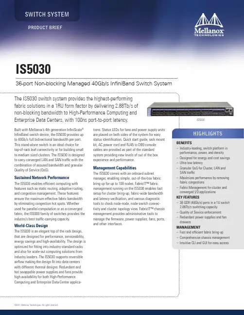
SWITCH SYSTEMIS503036-port Non-blocking Managed 40Gb/s InfiniBand Switch SystemIS5030©2011 Mellanox Technologies. All rights reserved.350 Oakmead Parkway, Suite 100, Sunnyvale, CA 94085Tel: 408-970-3400 • Fax: 3348PB Rev 1.1© Copyright 2011. Mellanox Technologies. All rights reserved.Mellanox, BridgeX, ConnectX, CORE-Direct, InfiniBlast, InfiniBridge, InfiniHost, InfiniRISC, InfiniScale, InfiniPCI, PhyX, Virtual Protocol Interconnect and Voltaire are registered trademarks of Mellanox Technologies, Ltd.FabricIT is a trademark of Mellanox Technologies, Ltd. All other trademarks are property of their respective owners.* Also available through Mellanox Certified Resellers and Distributors* Also available in short depth form factor and with 2 power supplies. Consult your Mellanox Sales Representative for further details.SAFETY–US/Canada: cTUVus –EU: IEC60950 –International: CB EMC (EMISSIONS) –USA: FCC, Class A –Canada: ICES, Class A –EU: EN55022, Class A –EU: EN55024, Class A –EU: EN61000-3-2, Class A –EU: EN61000-3-3, Class A –Japan: VCCI, Class A ENVIRONMENTAL–EU: IEC 60068-2-64: Random Vibration –EU: IEC 60068-2-29: Shocks, Type I / II –EU: IEC 60068-2-32: Fall TestOPERATING CONDITIONS –Operating 0ºC to 45ºC, Non Operating -40ºC to 70ºC –Humidity: Operating 5% to 95%, –Altitude: Operating -60 to 2000m,–Noise: 55dB - Noise reduction by controlling fan speed ACCOUSTIC –ISO 7779 –ETS 300 753 OTHERS–RoHS-5 compliant –Rack-mountable, 1U –1-year warrantyINFINIBAND SWITCH–36 QDFP non blocking switch with aggregate throughput of up to 2.88 Tb/s –Port-to-port latency < 100ns –IBTA 1.21 compliant–9 Virtual lanes: 8 data + 1 management –Adaptive routing –Congestion control –Port mirroring–48K entry linear forwarding data base MANAGEMENT PORTS –RS232 Console (RJ45) –Ethernet (RJ45) –USB portCONNECTORS AND CABLING –QSFP connectors–Passive/Active copper or fiber cable –Fiber media adapters INDICATORS–Per port status LED: Link, Activity –System status LED:Fan and power supplies LEDs POWER SUPPLY –Dual redundant slots –Hot plug operation–Input range: 100 - 240VAC–Frequency: 50-60Hz, single phase AC FANS–Front-to-rear or rear-to-front cooling option –Hot-swappable fan unit–Auto-heat sensing for silent fan operation –Fan speed controlled through management softwareCOMPLIANCEHARDWAREINFINIBAND–IBTA Specification 1.2.1 compliant–Integrated subnet manager agent–Adaptive routing–Congestion control–256 to 4Kbyte MTU–9 virtual lanes: 8 data + 1 management –48K entry linear forwarding data base –Port Mirroring MANAGEMENT–Fast and efficient fabric bring-up–Fabric-wide bandwidth verification–Comprehensive chassis management –Mellanox API for 3rd party integration –Intuitive CLI and GUI for easy access ©2011 Mellanox Technologies. All rights reserved.。

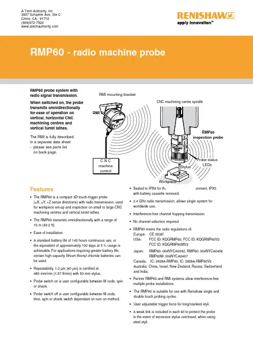
• 2.4 GHz radio transmission, allows single system forworldwide use.• Interference-free channel hopping transmission.• No channel selection required. • RMP60 meets the radio regulations of:Europe: CE 0536! USA: FCC ID: KQGRMP60, FCC ID: KQGRMP60V2 FCC ID: KQGRMP60MV2 Japan: RMP60: 004NYCA0042, RMP60: 004NYCA0406 RMP60M: 004NYCA0407Canada: IC: 3928A-RMP60, IC: 3928A-RMP60V2Australia, China, Israel, New Zealand, Russia, Switzerlandand India.• Partner RMP60 and RMI systems allow interference-freemultiple probe installations.• The RMP60 is suitable for use with Renishaw single anddouble touch probing cycles.• User adjustable trigger force for long/cranked styli. • A weak link is included in each kit to protect the probein the event of excessive stylus overtravel, when using steel styli.• The RMP60 is a compact 3D touch-trigger probe(±X, ±Y , +Z sense directions) with radio transmission, used for workpiece set-up and inspection on small to large CNC machining centres and vertical turret lathes.• The RMP60 transmits omnidirectionally with a range of15 m (49.2 ft).• Ease of installation.• A standard battery life of 140 hours continuous use, orthe equivalent of approximately 100 days at 5 % usage is achievable. For applications requiring greater battery life, certain high capacity lithium thionyl chloride batteries can be used.• Repeatability, 1.0 µm (40 µin) is certified at480 mm/min (1.57 ft/min) with 50 mm stylus.• Probe switch on is user configurable between M code, spinor shank.• Probe switch off is user configurable between M code,time, spin or shank switch dependant on turn on method.StylusData sheet H-2000-2122-03-A A Tech Authoirty, Inc3857 Schaefer Ave, Ste C Chino, CA. 91710 (909)972-7520Operating envelope - RMP60/RMIThe RMP60 transmission envelope and range is shown below.The probe system should be positioned so that the optimum range can be achieved over the full travel of the machine’s axes including the tool magazine. Always face the RMI in the direction of the machine spindle and tool magazine. If the probe is not in range when in the tool magazine use spin or shank turn on.The RMP60 and RMI must be within a mutual operating envelope. The operating envelope shows line-of-sight performance. However, radio transmission does not require line-of-sight as long as any reflected radio path is less than the 15 m (49.2 ft) system operating range.RMP60 probeRange metres (feet)OPERATING AND SWITCH ON/OFF75°0°15°90°75°60°75°0°19 (0.75)50 (1.97)RMP60 dimensionsdimensions mm (in)ZData sheetRMP60 - radio probeBattery dead - at this stage probe status is forced open and the probe cycle will stop.System operationPrior to probe operation, it is imperative that the program selected to ‘drive’ the probe has been verified. Incorrect programming could result in damage to the machine, workpiece and probe system.The RMP60 probe operates in one of three modes:1. Stand-by mode - The RMP60 uses a small current,while waiting for a switch-on signal to be received.2. Operating mode - Activated by one of the methodsdescribed below. Signals are only transmitted by the probe in this mode and the probe is now ready for use.3. Configuration mode - Trigger Logic™ allows a numberof probe set-up options to be programmed, by triggering the probe when the batteries are inserted. Programmableoptions are described on the next page.Probe environmentPrimary application Inspection probe for machiningcentres Sense directions 5 way ±X ±Y +ZWeight (without a shank) with batteries without batteries901 g (31.79 oz) 855 g (30.16 oz)Trigger force using 50 mm (1.97 in) stylus low force direction factory settingX Y 0.75 N / 75 gf (2.65 ozf)Z 5.30 N / 530 gf (18.69 ozf)Trigger force using 50 mm (1.97 in) stylus high force directionX Y 1.4 N / 140 gf (4.94 ozf)Z 5.30 N / 530 gf (18.69 ozf)Max. spin speed 1000 rev/minOvertravel X Y 18°Z 11 mm (0.43 in)Sealing IPX8 (BS 5490, IEC 529)1 atmosphereRepeatability maximum 2σ value in any direction 1.0 µm (0.00004 in) is valid fortest velocity of 480 mm/min(1.57 ft/min) at stylus tip, usingstylus 50 mm (1.97 in) long.Probe specificationProbe status LEDsWhen operating the probe status LEDs give a visual indication of the probe state (triggered or seated) and battery condition.Multiple probe modeRMP60 can be user configured using T rigger Logic™ to allow multiple RMP60s to be used with a single RMI.Notes:Radio turn on cannot be used in multiple probe mode. RMP60s set to ‘mode-on’ can coexist alongside any number of RMP60’s set to ‘mode-off’.To allow multiple probes/single RMI in close proximity, 16 choices of ‘mode-on’ colours are available – each representing a different machine tool installation.Only one of the multiple probes per machine will need partnering as, by configuring multiple probes to a single‘mode-on’ choice, all probes have the same identification. The probe to be partnered is partnered after selection of multiple probe on mode.There is no limit to the number of probes that can be used with a single RMI as long as they all have the same ‘mode-on’ colour choice.All RMP60s are factory-set to ‘mode off’.The addition of further probe(s) into a single probe installation requires all probes to be re-configured to the same multiple probe ‘mode-on’ choice and the repartnering of one of the probes to the installed RMI.The addition of further probes (or replacements) into a multi probe installation is achieved simply by reconfiguration to the same ‘mode-on’ colour choice.Comprehesive details of how to set-up and change mutiple probe settings are included in the RMP60 installation and user's guide, H-2000-5219.RMP60/RMI Temperature Storage -10 °C to 70 °C (14 °F to 158 °F)Normal operating5 °C to 50 °C (41 °F to 122 °F)Notes:The RMP60 will be turned on after 1 sec in all modes.)After being turned on, the RMP60 must be on for a minimum of 1 sec (7 seconds for spin option) before being turned off. In radio on configuration (either radio on/radio off or radio on/time off) the RMP60 has a built-in hibernate mode. This saves battery life when the RMP60 is in stand-by and the RMI is un-powered (or out of range).The RMP60 goes into hibernate mode 30 sec after the RMI is un-powered (or out of range). When in this mode, the RMP60 checks for a powered RMI every 30 secs, if the RMI is found, the RMP60 goes from the hibernate mode to stand-by, ready for radio turn on.Probe switch on and offThe probe is switched on by one of the following options.All options are user configurable.RMP60 switch-on method.Switch-on options are configurable.RMP60 switch-off method.Switch-off options are configurable.1. Radio onRadio switch on is commanded by M code. (factory setting).1. Radio offRadio switch-off is commanded by M code. (factory setting).A timer automatically switches the probe off after 90 min from the last trigger, if not turned off by M code.2. Timer off (time out)The RMP60 will time out (12, 33 or 134 sec - user configurable) after the last probe trigger or reseat.2. Spin startSpin at 650 rev/min for 1 sec minimum (6 sec maximum).3. Spin stopSpin at 650 rev/min for 1 sec minimum (6 sec maximum).A timer automatically switches the probe off after 90 min from last trigger off.4. Timer off (time out)The RMP60 will time out (12, 33 or 134 sec - userconfigurable) after the last probe trigger or reseat.3. Shank switch5. Shank switch offBattery life expectancyTypical battery reserve lifeUsing the standard alkaline battery at 5% usage, typically the probe will continue to operate for approximately 1 week after a low battery warning is first indicated.Replace the batteries as soon as is practicable.Rechargeable batteries: either nickel metal hydride (NiMh) or nickel cadnium (NiCd) can be used, but expect a battery life of approximately 50% of the alkaline figures given in the table below.To achieve stated radio stand-by life, the RMP60 must be in-range of a powered partner RMI.Battery Shank/spin turn onRadio turn on Continuous useTwo AA type Stand-by life (days - typical)5% usage 72 minutes/day (days - typical)Stand-by life (days - typical)5% usage 72 minutes/day (days - typical)(hours - typical)Alkaline65010013065140Lithium ThionylChloride1300200260130280For applications requiring greater battery life, certain high capacity lithium thionyl chloride batteries can be used.Data sheetRMP60 - radio probe(Ø2.48)RMP60M is a special modular version of RMP60. It enables probe inspection of part features inaccessible to RMP60, by fitting selected adaptors and extensions as shown.RMP60M modular systemRMP60M dimensions40.75 50.00 / 100.00 / 150.00 66.25 (Ø2.48)100.00 / 150.00 / 200.00 50.50 (Ø2.48)66.25Parts list - Please quote the Part no. when ordering equipment.TypePart no.DescriptionRMP60A-4113-0001RMP60 probe with batteries, tool kit and user’s guide (factory set to radio on/radio off).RMP60M module A-4113-1003RMP60M probe with batteries, tool kit and user’s guide (factory set to radio on/radio off).Battery P-BT03-0005AA battery - Alkaline type supplied as standard with probe (two required).Battery P-BT03-0008AA battery - Lithium thionyl chloride (two required).Stylus A-5000-3709PS3-1C ceramic stylus 50 mm long with Ø6 mm ball.Weak link kit A-2085-0068Weak link (Part no. M-2085-0069 x 2) and 5 mm AF spanner.Tool kit A-4038-0304Probe tool kit comprising: Ø1.98 mm stylus tool, 2.0 mm AF hexagon key,2.5 mm AF hexagon key (x 2), 4 mm AF hexagon key, and shank grub screws (x 2).Diaphragm kit A-4038-0302RMP60 outer diaphragm.Battery cassette A-4038-0300RMP60 battery cassette assembly.Cassette seal A-4038-0301Battery cassette housing seal.Bobbin kit A-4038-0303Bobbin for shank switch (supplied with shank).RMI A-4113-0050RMI, side exit, with 15 m (49.2 ft) cable, tool kit and user’s guide.Mtg brkt A-2033-0830Mounting bracket with fixing screws, washers and nuts.Extension L100A-4038-1010RMP60M extension - 100 mm long.Extension L150A-4038-1027RMP60M extension - 150 mm long.Extension L200A-4038-1028RMP60M extension - 200 mm long.Probe module A-4038-1002RMP60M probe module assembly.RMP60/LP2 adaptor A-4038-0212RMP60M LP2 adaptor assembly.LPE1A-2063-7001LPE1 extension bar - 50 mm long.LPE2A-2063-7002LPE2 extension bar - 100 mm long.LPE3A-2063-7003LPE3 extension bar - 150 mm long.MA4A-2063-7600MA4 90° adaptor assembly.RMP60 user’s guide H-2000-5219RMP60 user’s guide.Styli –See brochure H-1000-3200 Styli and accessories.Software –See data sheet H-2000-2289 Probe software for machine tools.Shanks –See data sheet H-2000-2011 Shanks.RMI–See data sheet H-2000-2123 RMI.Renishaw plcNew Mills, Wotton-under-Edge, Gloucestershire GL12 8JR United KingdomT +44 (0)1453 524524F +44 (0)1453 524901E ***************© 2006 Renishaw plc. All rights reserved. Renishaw reserves the right to change specifications without noticeIssued 11.06 Part no. H-2000-2122-03-AFor worldwide contact details, please visit ourmain web site at /contact*H-2000-2122-03*。


With the development of thePOSIDRIVE ®MDS 5000 servoinverter, STÖBER ANTRIEBS-TECHNIK is launching a totalrevision of the hardware andsoftware for the servo system.The data communication between the POSIDRIVE ® MDS 5000 and the STOBER ED EK and EZ synchronous servo motors is now entirely digital.The main factor allowing rationalrealization of this fully digital ser-vo axis lies in the developmentof fully digital absolute encodersat industrial-scale prices. TheSTOBER synchronous servo mo-t ors in the ED, EK and EZ series are equipped with these devices.Innovative software generation The commissioning software POSITool is based on a com-pletely new, mo d ular 3-layer architecture with ergo n o m ic interface de s ign. An ap p li c ations library with pa - r am e terization assistant and an additional flexible graphics pro -gramming facility forms a suc -cessful bridge between custom-made design and universality.This new system technologybrings to an end the era of over-loaded and confusing operatingprograms from the pioneering period of inverters.The benefits are obvious This comprehensive and rational slimming down of the sys t em results in significant cost bene-fits for hardware, configuration,cabling, installation and com -mis s ioning.The close coordination of all the STOBER servo components is clear from the example of the electronic motor rating plate.Its data is used automatically in the parameterization of the POSIDRIVE ®MDS 5000 servo inverter.THE FIRST COMPLETE SYSTEMFOR EFFICIENT AUTOMATIONTHE FULLY DIGITALPOSITIONING AXISSTOBER EK synchronous servo motorwith digital absolute valuator(standard version)2Multiple use by alternatecontrol of different servodrivesServo drives often go into actionat timed intervals. Typical exam-ples of this are handling opera-tions and format adjustments.Multimotor operation with onlyone POSIDRIVE ®MDS 5000servo inverter is suitable forthese applications.The digital technology makes it possible For the first time the inexpensiveand reliable axis changeoverapplication is available for un -restricted use on servo drives.Axis changeover switchThe POSISwitch ®AX 5000 exter-nal module has been developedfor connection of the digitallycontrolled synchronous servomotors. Actuation is just via theexisting encoder cables, with-out further operations.Power and signal flows are controlled with correct timing.The axis management does not require additional software complexity in a primary control.Sequential operation with -out functional limitation If four drives are used as end -less axes with absolute encod -ers, the exact positioning is stillfree from rounding errors evenif the gear units have differentand non-integer gear ratios.POSISwitch ®AX 5000Software The POSITool software can man -age up to four separate position or speed regulated axes and control them alternately.A smooth transition from axis to axis is guaranteed by thesoftware.ALTERNATECONTROL OF SEVERALSERVO DRIVES3For experts The new, user programmable firmware has been upgraded to include a graphics editor layer in conformance with PLCopen ®.An experienced or trained user will find a variety of predefined function blocks in various libra-ries. With these, basic applica-tions can be modified or given extra functions.Extra service For a completely new functio-nality requirement or for com -prehensive adaptation of the basic application, STÖBER ANTRIEBSTECHNIK offers this as "tailor-made applications"service.Other highlights The software scalability allows optimum adaptation of functio-nality and response time to the application. The cycle time for setpoint processing depends only on the calculation of the activated system modules and the plex applications can also be mapped on the same hard-ware platform without modify-ing the firmware.The STOBER POSISwitch ®AX 5000 axis changeover switch is prepared for use on the soft-ware side. Up to 4 servo axes with different functionalities can be controlled alternately.The rapid pace of developmentsin electronics is leading to con -tinuous improvements and ex -panded functions, especially inservo inverters, and yet this isassociated with constant growthin user software com p lexity. Atrend which is in stark contrastto the demand for sim p ler andmore accurate usability.This conflict of objectives hasbeen addressed by STÖBER ANTRIEBSTECHNIK and Soft-ware Suite V5 developed as a solution. This suite includesthe commissioning softwarePOSITool, a comprehensivelibrary with standard applica-tions, as well as the firmwarefor the inverter generation 5000.Instead of rigidly defined firm-ware with an endless numberof parameter variations the userhas a modern, ergonomicallydesigned operator interface.MODULARSOFTWARE ARCHITECTUREMODULAR H Functional housing design As part of the STOBER EMC strategy, all the housings in the POSIDRIVE ®MDS 5000 series are made of galvanized sheet steel. They shield against elec-tromagnetic interference and thus increase the units' RFI immunity and reduce interfe-rence emission.The front housing is made of high-impact plastic and incor -porates the operator keypad,display, LED indicators, Para -modul and RS232 interface,along with the slots for the op -tional boards and terminals.The same design plastic front housing is used for all the sizes.SYSTEM CONCEPT OF TOTAL MODULARITY Paramodul Plug-in memory module for transf er of all program and set -tings data.If a POSIDRIVE ®MDS 5000 has to be replaced, the existing Paramodul is simply plugged in again to restart operations. The functionality is retained without restriction. This plug-in memory module is also an ideal, immediately avail -able tool for documentation up -dating of operating conditions.4For everyday To configure a drive, the com-missioning software POSITool offers a li b rary with typical preproduced basic applications.Here is a selection:b Fast reference value b Comfort reference value Speed or torque reference value (selectable)3 analog reference values 16 fixed reference valuesMotorized potentiometerPID controller reference valueReference values scalable asabsolute or percentage valueb Command positioningPowerful single axis position-ing control with commandinterface in accordance withPLCopen ®and the additionalfunction POSILatch. Positionmeasurements can then betaken on external signals(e.g. linear measurements)b Motion block positioningb Electronic cam functionConnection of up to 32 axesThe consistent project orienta-tion of the modules is provingextremely effective.The parameterization work issupported by assistant func-tions.EMC shield, the motor cable shield connected with a clipOn the right: Version with integral brake module for 24 V brake ARDWARE STRUCTUREDP 5000PROFIBUS DP-V1CAN 5000CANopen DS 301Optional fieldbus communicationOptionalI/O interfacesSupply connection 3 x 400 VoltsXEA 5001I/O terminal module – expanded –3 analog inputs (1 x 16 bit, 2 x 12 bit)2 analog outputs 13 binary inputs 10 binary outputs 2 x D-SUB 9 incremental encoder (TTL) or SSI Input/output interface (X20 – SDS compatible)SEA 5001I/O terminal module– standard –2 analog inputs (12 bit)2 analog outputs5 binary inputs2 binary outputsEncoder interfaces for 4 systems:EnDat digital (bidirectional synchronous serial interface)SSI-AbsoluteTTL incremental encoder (RS422, “5V”)HTL incremental encoder (“24V”)24 Vsupply 5ECS 5000EtherCAT PROFINETREA 5001I/O terminal module – Resolver –2 analog inputs, 2 analog outputs 5 binary inputs, 2 binary outputs Encoder:Resolver EnDat -Encoder 2.1TTL incremental encoder*SSI encoder*Stepper motor signals*The adapter is included in the scope of delivery of the REA 5001*(Simulation and evaluation)THE COMPLETE RANGEFROM 0.37 TO 45 KW Installation The POSIDRIVE servo inverters can be mountedin compact control cabinets300 mm deep.The operator module is thesame for all the sizes.The sheet steel housing designis part of the STOBER EMCstrat e gy (filter class A). It shieldsagainst electromagnetic inter-ference.6This increases the units' RFI immunity and reduces interfe-rence emission. The front is the only part made of plastic which is pleasant to the touch.Functional modular housing designMDS 5007A/5008A/5015A MDS 5040A/5075A MDS 5110A/5150A MDS5220A/5370A/5450ASYSTEM BASISPowerful processor core32-bit RISC processorCurrent controller 125 µs Control modes Synchronous servo motors Asynchronous motors (V/f, sensorless VC, VC)Encoder interface Absolute encoder, digital (EnDat ®, SSI)Incremental encoder (TTL, HTL)Optional: Resolver Serial interface RS232 with USS protocol Option board slots Communication I/OTerminals Operational reliability Generously sized power stage for 250 % accelerating current Thermistor motor protection PTC thermistor monitoring Brake chopper integral Thermal model monitoring of external resistor for short circuitand overload DC link connection For energy exchange between several inverters Operator unit 8 keys, changing of parameters,manual operation (clear text display and LED indicators)Paramodul Plug-in module for power failu-re safe storage of all application specific data.Data transfer without any fur -ther aids Control electronics supply Power supply unit with connec-tion facility for external +24V orDC link power supply(the control section remainsfully functional even if the sup -ply voltage is switched off)Ease of installation All terminals plug-in type (spring-loaded terminals)Supply and motor connectionsin separate placesDC link terminals, two of each,facilitate parallel connectionEMC plate for shield connection ASP 5001 Option for the implementation of safety functions:b STO and SS1 as perEN 61800-5-2b Stop category 0 and stopcategory 1 as perEN 60204Integration is possible forapplications up to (max.):b PL e in category 3 as perEN ISO 13948-1:2008-12 andb SIL 3 as perEN 61800-5-2:2008-04The POSILatch function uses externalsignals and evaluates them as measure-ment function.POSILatch can replace a separate PLCmeasuring system7POSITool Windows Software Application selection (with assistant)Parameterization (with assistant)Manages several servo inverters in one installationDrive optimization with POSI-Scope, oscilloscope function forinternal signals (movementvisualization), operational datamonitoring and diagnosisFieldbus communication PROFIBUSPROFINETEtherCAT®CANopen®I/O terminal moduleSEA 5001XEA 5001 (incremental encoder and SSI interfaces)REA 5001Resolver andEnDat®Encoder 2.1 interfacePOSISwitch®AX 5000For sequential control of STOBER ED, EK and EZ synchronous ser-vo motors with digital absolute encoders.Submountedbraking resistorsBraking resistors for installation at the rear of the unitBraking resistorVHPR seriesIP 54 enclosure, ULVHPRBraking resistorASP 5001Starting lockoutSYSTEM OPTIONSCE complianceAll POSIDRIVE®MDS 5000 inver-ters conform to the applicableEMC Directives and meet thecriteria of Low Voltage DirectiveEN 50178. Standard featurescomprise an effective range ofmeasures, among them an in -tegral EMC filter and the high-quality galvanized sheet steelinverter housing.Levels and terms apply as de -fin e d by IEC 1131.All POSI D RIVE®servo invertersare CE-markedUL compliantThe inverters are UL and cUL("Canadian UL") listed and meetthe requirements of UL 508Cand UL 840 standardsAbsolute Encoder Support AESFor buffering supply voltagewhen using the inductive Multi-turn EnDat®2.2 absolute encoderEBI1135 (when the 24 V powerCommissioningfer via the device operator panel.The Paramodul is also suit a ble for data transfer. Further pa -rameterization cor r ections and additions can be made directly.Some knowledge (basic training)is necessary for this missioning the STOBERED, EK and EZ synchronousservo motorsNo software knowledge is neces-sary for this preparation work.All the adjustments are done bydialog via the operator panel withtext display. The POSIDRIVE ®MDS 5000 servo inverter comessupplied with the “rapid set point”application.synchronousservo motorwith digitalabsolute encoderon the motorshaft (B side)Advanced seminars for general users and experts The POSITool software assistant supports configuration and pa-rameterisation of the STOBER standard applications. Basic andadvanced information on the safehandling of POSITool necessaryon the job can be acquired at anapplication seminar.In practical, individually designedseminars, general users learnthe ways in which they can uti-lise the potential of the POSIToolstandard applications fully andeffectively.After attending the ‘Free GraphicProgramming’ seminar, expertscan expand the POSITool stan-dard applications themselvesto adapt them to specific needs.Further information and datescan be found on our websitewww.stoeber.de (Services).ServiceThe STOBER service system comprises38 expert partners in Germany andmore than 80 companies in the STOBERSERVICE NETWORK worldwide.This full service concept guaranteeslocal expertise and availability whenneeded.In general, the service specialists can bereached at any time via a 24/7 servicehotline.When necessary, a problem can beaddressed immediately.24/7 service hotline+491805786323QUICK TO ASSEMBLESubjecttotechnicalchanges441812.7www.wast.deQuick DC link connection.Double DC link permit enablesimplified parallel connection.The separate connections formotor, DC link and braking re -sistor are located on the bot t omof the housing. The PTC therm -istor and braking relay are alsoattached here by simple plug-inmounting.VERY EASY TO USEEasy data transfer and accep-tance by Paramodul.Display and keypad are inte-grated. Rapid diagnosis, statusmonitoring, direct parameteraccess and manual operatingfunctions are possible.Perfect, practical connectionlayoutThe mains or 24V supply con -nection is made ‘from above’through a plug-in terminal strip.STOBER AUSTRIAwww.stoeber.at+43 7613 7600-0****************STOBER CHINA+86 10 6590 7391****************STOBER FRANCEwww.stober.fr+33 4 78.98.91.80***************STOBER GERMANYwww.stoeber.de+49 7231 582-0****************STOBER ITALYwww.stober.it+39 02 93909570***************STOBER JAPANwww.stober.co.jp+81 3 5395 6788***************.jpSTOBER SOUTH EAST ASIAwww.stober.sg+65 65112912***************STOBER SWITZERLANDwww.stoeber.ch+41 56 496 96 50****************STOBER USA+1 606 759 5090****************。
SPRINGFederal Flyer20148am–8pm (et)24 Hours s mSpring EditionJOIN OUR COMMUNITY14FD11548am–8pm, et • To Fax:1.877.350.789024 Hrs 3Lidocaine HCl 2% withEpinephrine Injection, USP 1.8-mL Anesthetic Cartridges• Validated siliconization process: ensures smooth injection• Meets all FDA requirements: allows total flexibility in brand selection• Color-coded stoppers and labeling: easy identification of each anesthetic formula • Mylar ®wrap: prevents breakage• Blister packaging: no glass/glass contact 1:100,000, Red(465-1205).........................50/boxContains: 5 blister packs of 10 cartridges per package.1:50,000, Green(465-0015).........................50/boxContains: 5 blister packs of 10 cartridges per package.Approved for sale only to licensed practitioners in the US.Oraqix ®Lidocaine and Prilocaine Periodontal Gel 2.5%Patient-friendly, needle-free application that dispenses as a liquid, then sets as a gel at body temperature. Ideal for patients requiring local anesthesia in periodontal pockets during scaling and/or root planing. Applied to gingival margin, then to periodontal pocket. Fast,30-second onset provides 20 minutes of anesthesia. Unique, easy-loading dispenser provides increased access to all periodontal pockets.(555-4520)...............................Ea.(555-0626).........................20/BoxOraVerse™ (Phentolamine Mesylate) InjectableIndicated for reversing soft-tissue anesthesia and the associated deficits from an intraoral submucosal injection of a local anesthetic containing a vasoconstrictor. Patientsexperience a return-to-normal sensation andfunction in about half the time. Not recommended for children less than 6 years of age.0.4 mg./1.7 mL Cartridges(228-2237).........................10/Box14FD1154TRANSPARENT MIXING PADS100 Sheets per PadTransparency of the pad allows you to see the product and how well it has been mixed before you apply.• Nonslip foam backing allows mixing without movement of the pad• Great for cements, liners, composites, and impression materials23/4" x 31/8"(900-4265)................................ea 31/8" x 51/2"(900-4266)................................eaNATURAL ELEGANCE ®RESIN CEMENTDual-Cure Automix Resin CementDual-cure, automix resin cement. High bond strength for longer lasting restoration. Use for a wide variety of dental restorations, including metal, composite crown/bridge, inlays, onlays,posts, and ceramic and porcelain crowns.• Versatile shading with 3 levels of opacity • Microparticulate formulation provides high bond strength for longer-lasting restorations • Designed for use for cementing all ceramic and all-composite indirect restorations (veneers, crowns, inlays, and onlays) and for intraoral porcelain repair Syringe Refills ........................eaSpecify:A2..................................................(900-4110)White..............................................(900-4111)Translucent....................................(900-4112)Automix Mixing Tips–Brown(900-7434).........................20/pkgGC FujiCEM ™2Resin-modified, glass-ionomer luting cement.Powered by F 2Flex Fuse Technology, which improves indirect restorations with increased strength, high fluoride release, low film thick-ness, and excellent marginal integrity. Use on all types of metal, resin, alumina, and zirconia-based inlays, onlays, and crowns and bridges.Radiopaque.Introductory Kit(333-3271)................................eaContains: 1–13.3 Gm cartridge, 20 mixing tips & 1 dispenser.Refill Package with Tips(333-3267)................................eaContains: 2–13.3 Gm. cartridges & 44 mixing tips.Refill Package without Tips(333-3268)................................eaContains: 1–13.3 Gm. cartridge & 1 mixing pad.Mixing Tips(333-2234).........................20/pkgDispenser(333-3270)................................ea8am–8pm, et • To Fax:1.877.350.789024 Hrs 5SureFil ®SDR ®Flow Posterior Bulk Fill Flowable Base Posterior, light-cured, bulk-fill, flowable composite base. The advanced StressDecreasing Resin (SDR) technology features an extended pregel phase that absorbs the polymerization stress buildup within the composite by up to 60%. Can be placed in increments up to 4mm. Radiopaque and contains fluoride.Introductory Kit(222-0225)................................eaContains: 25–0.25 Gm. Compula ®tips & 1 Compule ®tip gun.Refill Package ........................eaSpecify:A1..................................................(222-0346)A2..................................................(222-0347)A3..................................................(222-0348)Contains: 15–0.25-g Compula ®tips.Bulk Kit(222-0282)................................ea Contains: 50–0.25-g Compula ®tips.OptiBond ®Solo Plus ™A 15%-filled, single-component, light-cure adhesive. The optimum particle size allows it to be used for direct and indirect applications,providing the ultimate in convenience,protection, and strength.Bottle Kit(123-1507)................................ea Unidose Kit(123-0155)................................eaContains: Bottle Kit: 2–5-mL OptiBond Solo Plus adhesive,1 gel etchant syringe, 10 gel etchant syringe tips, 25disposable mixing wells, & 50 disposable applicator tips.Unidose Kit: 100 OptiBond Solo Plus packets (10 mL total),1 gel etchant syringe, 10 gel etchant syringe tips, & 50disposable applicator tips.Paradigm ™Nano Hybrid CompositeNanohybrid universal restorative. Excellent strength and wear resistance. Easy to polish.No slumping and easy to shape. Does not stick to instruments. Use for anterior and posterior restorations.Capsule Refills.................20/pkgSpecify:A1....................................(777-0381)A2....................................(777-0382)A3....................................(777-0386)B1....................................(777-0390)B2....................................(777-0391)Opaque A2.......................(777-0403)Opaque A3.......................(777-0404)14FD1154SafeGauze ®Green Nonwoven Sponges 2" x 2"(113-5501)....................4000/case 4" x 4"(113-5494)....................2000/caseTranslucent Plastic Cups Embossed Drinking Cups with Rolled Lips 5 oz(104-9869).......................100/pkgSaliva EjectorsSmooth edges. Will not aspirate tissue.Flexible bonded tips. Latex-free.Disposable.....................100/bagSpecify:White Opaque................................(100-5205)Clear with Blue Tip........................(100-4092)Pink................................................(900-4272)Plastic Drinking Cup DispenserClear plastic with white base. Attaches to wall and holds 50–5-oz plastic cups.(100-2626)................................ea8am–8pm, et • To Fax:1.877.350.789024 Hrs 7Polycoated Headrest Covers Soft, facial tissue combined with poly. Providesstrong, absorbent, fluid-resistant barrier.Small10" x 10"......................500/caseSpecify:White..............................................(107-1143)Lavender........................................(108-7903)Blue................................................(108-9564)Regular10" x 13"......................500/caseSpecify:White..............................................(107-0548)Dusty Rose....................................(107-7590)Lavender........................................(107-1341)Blue................................................(108-9803)Green.............................................(108-7228)Jumbo13" x 13", White(107-1231)......................500/caseTIDI ®Slipover Adult Bibs Fabricel, 20" x 30"(101-8381)......................250/case XL Tissue/Poly, Die-Cut Neck Blue, 20" x 29"(895-6634)......................500/case Mauve, 18" x 25"(101-7499)......................250/case Tissue/Poly Slipover White, 18" x 30"(895-7875)......................150/caseEAR LOOP PROCEDURE FACE MASKSLight, comfortable masks for extended wear when necessary. Ear loops are made from special stretch yarn: no irritating rubber or plastic touches the skin. Three-ply, glass-free filter media is surrounded by soft, nonirritating inner and outer facing. Full-width flexible nosepiece provides fit and security. Exceeds all current ASTM F2100-03a tex-free.Face Masks.....................50/boxSpecify:Blue................................................(104-3809)White..............................................(104-6611)Lavender........................................(104-8600)Pink................................................(104-3730)Yellow............................................(104-2849)ASTM: Level 1 l PFE:≥98% @ 0.1 micron (μ) l BFE:≥95%14FD1154Confirm ®10 In-OfficeBiological Monitoring System Now with 10-hour test results. Easy to use:simply process indicator in a normalautoclave cycle, then follow with a 10-hour incubation cycle. A color change to yellow indicates failure to sterilize.In-Office Monitor(774-0123)................................ea Indicator Refills(774-0124).........................25/boxMonarch ™Surface Disinfectant One-step, ready-to-use,hospital-level disinfectant for use on nonporous surfaces.EPA-registered, broad-spec-trum disinfectant. Effectively kills TB, HBV, and all bacteria and fungi in less than 1 minute. Noncorrosive and nonstaining. Contains no phenols or aldehydes.Spray Bottle(698-0420)..........................24 oz.Refill(698-0429)........................102 oz.Super Sani-Cloth ®Intermediate-level disinfectant that kills 26microorganisms with a fast kill time of only 2 minutes on hard, nonporous surfaces and patient-care equipment. Contains 55% alcohol.Bactericidal, tuberculocidal and virucidal.• Kills TB and RSV in 1 minute; HBV, HCV and HIV-1 in 2 minutes; TB, MRSA, VRE, influenza A (H1N1) virus, Acinetobacter baumannii ,Campylobacter jejuni in 2 minutes • Kills Candida albicans and rhinovirus • Diamond-embossed material is thick and strong to help clean soiled surfaces CanistersLarge, 6" x 63/4"(113-5423)......160 wipes/canister X-large, 81/2" x 15"(267-0005)........65 wipes/canister X-Large, 111/2" x 113/4"(373-2662)...............50 wipes/boxFlipEase ™Eye Protection Ready-to-wear eye protection.Comes flat and assembled. Just flip!• Fits comfortably with a mask and over glasses • CE certified• Revolutionary, patent-pending design • Extremely lightweight and comfortable • Provides front and side eye protection • Optical-grade, anti-static, fog-resistant (895-0045).........................25/Box8am–8pm, et• To Fax:1.877.350.789024 Hrs9Microflex®XCEED™NitrilePowder-FreeNon-sterile, BluePolymer technology, textured fingertips,beaded. Palm thickness: 2.8 mil.;Finger thickness: 3.5 mil.Gloves............................250/boxSpecify:X-small...........................................(565-0003)Small..............................................(565-0004)Medium..........................................(565-0005)Large..............................................(565-0006)X-large(565-0007).......................230/boxCriterion®N200 Powder-FreeNitrile Exam Gloves• Eliminates type-1 allergic reactions associatedwith natural latex• Innovative formulation emulates the fit and feelof latex with added strength and punctureresistance• Eco-friendly, 200-count box increases yourstorage by 50%, reduces cardboard waste,and still fits your glove box holders. You savemoney while reducing yourenvironmental impact• “Real-feel” grip provides optimal tactile sensi-tivity, and textured fingers provide enhanced,superior grip in both wet and dry applications• Easy donning: very smooth inside, so gloveslides onto your hand with ease. No need tofight with it when you are in a hurryGloves............................200/boxSpecify:X-small ..........................................(900-7437)Small .............................................(900-7438)Medium .........................................(900-7439)Large ............................................(900-7440)X-large (180/box) ..........................(900-7441) Ultraform®Nitrile Powder-Free ExamIncreased tactile sensation and improvedcomfort. Soft formulation conforms to thehand effortlessly. Textured. Higher-countbox. Colbalt Blue.Gloves............................300/boxSpecify:X-Small..........................................(565-0013)Small..............................................(565-0014)Medium..........................................(565-0015)Large..............................................(565-0016)X-Large(565-0017).......................250/box14FD1154ProFluorid ®Varnish5% sodium-fluoride varnish delivers with enhanced flowcharacteristics for hard-to-reach areas. Single-dose delivery systemadheres to moist surface and sets quickly after contact with saliva. White, transparentvarnish without yellow discoloration immediately releases fluoride to relieve hypersensitivity.Contains no saccharin, aspartame, or gluten.Single Dose, 0.25 mL, Kids, Melon (840-9282).........................50/boxSingle Dose, 0.4 mL, Adult/Assorted Flavors(999-1366).........................48/boxContains: Carmel, Cherry, Melon and Mint.Single Dose, 0.4 mLAdults....................................................50/boxSpecify:Caramel.........................................(999-1362)Cherry............................................(999-1363)Melon.............................................(840-9285)Mint................................................(999-1364)Single Dose, 0.4 mLAdult...............................200/boxSpecify:Caramel.........................................(999-1367)Cherry............................................(999-1369)Melon.............................................(999-1370)Mint................................................(999-1368)10 mL Tube............................eaSpecify:Caramel.........................................(999-1669)Cherry............................................(999-1670)Melon.............................................(114-3932)Mint................................................(999-1671)Sensodyne ®Repair &Protect ToothpasteProvides proven relief and daily protection for sensitive teeth. Relieves the pain and helps to stop it from coming back by creating a repair layer over sensitive areas. Contains fluoride for cavity protection.3.4 oz. Bottle..........................eaSpecify:Original ..........................................(583-1303)Extra Fresh....................................(583-1316)G•u•m ®Toothbrushes Adult Angle......................12/pkgSpecify:#430, Soft, Full Size......................(712-1189)#431, Soft, Compact Size..............(712-1845)#435, Sensitive, Compact Size .....(712-3344)8am–8pm, et• To Fax:1.877.350.789024 Hrs11Hand Essentials™Skin Repair CreamContains Olivamine®, a patented blend of ingredients that delivers all of theessential nutrients necessary for optimal skin health, including amino acids,vitamins, antioxidants, and methylsulfonlymethane (MSM). Natural moisture-retaining oils, aloe vera, and dimethicone leave the skin feeling silky with nogreasy residue. Specially formulated for dental professionals who are at riskfor skin breakdown.2-oz Bottle(600-1906)...................ea Call4-oz Bottle(600-1907)...................ea Call32-oz Bottle(600-1908)...................ea Call(600-1912)........144/case CallMonarch™HydratingInstant Hand SanitizerWaterless, alcohol-based gel.Smooth application with a silky feel.Contains no hormone-disruptingsurfactants. Skin-enriching emol-lients enhance skin-cell regrowthand prevent dryness with repeateduse. Maintains moisture duringrepeated washings.Personal Size(698-0426)............................2 oz.CallPump Bottle(698-0421).........................15.2oz Call Antibacterial LiquidHand SoapProvides a luxurious feel, leavinghands smooth and soft. Mild, gentle,and moisturizing. Pleasant cucumberand aloe fragrance. Active ingredientis 0.2% triclosan.8-fl-oz Pump Bottle(900-4439)................................ea Call16-fl-oz Pump Bottle(900-4438)................................ea Call1-gal Refill Bottle(900-4440)................................ea Call14FD1154JAZZ™C1S 1-Step Single-PatientPolishing SystemDiamond impregnated to achieve a highgloss on all direct-aesthetic materials.Single-patient use saves sterilization costand time.Assortment Pack(999-0670)................................eaContains: 12 universal polishers (4 of each shape:cup, disc & flame).Refills...............................20/pkgSpecify:Flame.............................................(999-2315)Cup................................................(999-5060)C-TYPE HANDPIECES• Canister-type cartridge:for easychairside replacement• Powerful:400,000 rpm at 32 psi• Smooth finish:for easy maintenance• Mini head:Compact size for greateraccess and visibility• Ergonomic design features• Lightweight and quiet operation• 400,000 rpm at 32 psi• 4-hole connection• Manual chuck• Easy chairside replacement of turbine cartridge• Fully autoclavable• 6-month warrantyC-Type Handpiece(112-4122)................................eaC-Type Replacement Cartridge(112-3909)................................eaC-TYPE MINIATURE HANDPIECE• Canister Type Cartridge:for easy chairsidereplacement• Powerful:400,000 rpm at 32 psi• Smooth Finish:for easy maintenance• Mini Head:Compact size for greater accessand visibilitySame features as the C-Type Handpiece butwith smaller head size for greater access andvisibility.4-Hole(112-5578)................................eaPUREVAC®2-liter BottleYields 67 uses.(312-6475)................................ea5-liter BottleYields 169 uses.(312-5825)................................ea8am–8pm, et • To Fax:1.877.350.789024 Hrs 13Evacuator Tips• Unique “S” tips with a softer end for patient comfort • Latex-free• Opaque plastic • Disposable Nonvented(100-4568).........................50/bag Vented (One End Only)(101-4856).........................50/bagINSTRUMENT CASSETTES • Stainless steel locking tray complete with silicone rails for storing dental instruments • Fully autoclavable, features unique design that optimizes sterilization process• Upper and lower sections of tray are fully interchangeable• Colored rails for instrument identification and organization 5-Instrument Tray7.1" x 2.8" x 1.3".....................eaSpecify:Blue................................................(112-4963)Green.............................................(112-5301)Purple ............................................(112-5336)Red................................................(112-5297)Yellow............................................(112-5442)10-Instrument Tray7.1" x 5.6" x 1.3".....................eaSpecify:Blue................................................(112-4964)Green.............................................(112-5302)Purple ............................................(112-5439)Red................................................(112-5299)Yellow............................................(112-5443)16-Instrument Tray11.3" x 7.1" x 1.3"...................eaSpecify:Blue................................................(112-4965)Green.............................................(112-5303)Purple ............................................(112-5441)Red................................................(112-5300)Yellow............................................(112-5444)MaxiTabs ™Ultrasonic Cleaning Tablets General Purpose Cleaner• Provide safe and effective cleaning properties in multiple cleaning cycles throughout the day• Does not leave a residue on instruments or insidetank• 1 tablet makes 1 gallon of solution • 1 box makes 32 gallons General Purpose Cleaner(900-4088).........................32/boxTartar & Stain Remover• Offers safe and effective cleaning efficacy for removal of calculus, tartar, tobacco,and food stains• Specifically designed for dentures,bridges, and dental appliances. 1 tablet makes 5 oz of solution(900-4089).........................32/boxDRI-GARD ®CSR WRAP • All-purpose sterilization overwraps• Provide high protection against air- and fluid-borne particles, yet allow effective penetration for various methods of sterilization, including steam, ethylene oxide, radiation, and E-beam • Resistant to tears and punctures• Conform to various pack and tray sizes and are easily secured with standard adhesives or tapes for full enclosure and assured sterility • Autoclavable, 1-ply sheets 12" x 12"(900-7447)......................500/case 15" x 15"(900-7448)......................500/case20" x 20"(900-7449)......................500/case24" x 24"(900-7450)......................500/caseMaxi-Gard ®Fitted Digital Sensor Sleeves• Disposable, fitted digital sensor sheaths helps prevent cross contamination• Soft, textured vinyl with rounded corners fits the sensor snugly to maintain the position of the bite tab and enhance patient comfort• Large opening for easy sensor loading and simple tear-away design for instant sensor removal• Comes conveniently packaged in a dispenser roll • Latex-free Size 1(1.638"W x 7.465"L x 1.262" Head Size)Fits Kodak 6100 #0, Schick Elite #0,Schick #0 & #1, Gendex GX-S #1, EVA #1,XDR #1, Instrumentarium Sordex #1,Progeny #2, Myray #1, and Planmeca #1.(112-6020).......................500/boxSize 2(1.638"W x 7.465"L x 1.342" Head Size)Fits Kodak 6100 #1, Schick Elite #1, Schick,Gendex GX-S #2, EVA #2, and Plameca #1.(112-6021).......................500/boxSize 3(1.88"W x 7.465"L x 1.506" Head Size)Fits Kodak 6100 #2, Schick Elite #2, Dexis #2,XDR #2, Instrumentarium Sordex #2, EVA+ #2,MyRay #2, and Planmeca #2.(112-6023).......................500/boxFlex Bite Tabs • Adjustable bitewing tabs• Fits snugly over digital sensors, conventional film,and phosphor plates of all sizes• Universal for both horizontal and vertical angles • Made with ultrasoft material for enhanced patient comfort(112-6019).......................300/box14FD1154Sterile Surgical Blades Manufactured by Kai.Stainless Steel Blades...100/boxSpecify:#10, Part #4-310............................(953-6694)#11, Part #4-311............................(953-7469)#12, Part #4-312............................(953-7546)#12B, Part #4-312B.......................(953-6343)#15, Part #4-315............................(953-7616)#15C, Part #4-315C.......................(953-7101)#20, Part #4-320............................(953-7810)#21, Part #4-321............................(953-7906)#22, Part #4-322............................(953-8126)#23, Part #4-323............................(953-8193)#25, Part #4-325............................(953-3557)Lifepak ®1000An easy-to-use and rugged AED that isadaptable enough for professional responders.Features a large, intuitive screen that displays graphics and ECG readings that are clear and easy to read. 5-year warranty.Lifepak ®1000 Unit with Graphical Display Pediatric ready: includes an infant/child reduced-energy electrode starter kit.(373-0005)................................eaLifepak ®Unit with ECG DisplayIncludes a 3-wire ECG cable and pouch plus a 3-pack of Life-Patch ®ECG electrodes.(373-0006)................................eaContains: cprMax ™Technology, 2 pair of Quik-Combo ®pacing/defibrillation/ECG electrodes with 1 Redi-Pak ™preconnect system, 1 set of operating Instructions, 1 “Getting Started” guide, 1 nonrechargeable lithium-manganese-dioxide battery, 1 soft-shell carrying case & 1 shoulder strap.Sterile Suture Removal Kit with Floor-Grade Instruments(788-1565)................................eaContains: 1pair floor-grade Iris suture scissors,1pair floor-grade Adson tissue forceps, 3" x 3" gauze sponge,large alcohol prep pad, & iodophor PVP prep pad.8am–8pm, et• To Fax:1.877.350.789024 Hrs15Proudly supports all of your dental, medical, and supply needs.S UPPORTING YOUR SUPPLY NEEDS THROUGH THE FOLLOWING CONTRACTS:DLA ECAT Dental Program SPM2DE-09-D-7444DLA ECAT Lab Contract SPM2DE-10-D-7342DLA Medical/Surgical DAPA Holder SP0200-96-H-5014FEDERAL SUPPLY SCHEDULES:Pharmaceuticals and Drugs (Anesthetics) V797P-2280DDental Equipment and Supplies V797P-3160M X-ray Equipment and Supplies V797P-3022MHENRY SCHEIN, INC. IS A PROUD FEDERAL SUPPLY SCHEDULE DISTRIBUTOR FOR:Welch Allyn—Medical Equipment and Supplies V797P-4333B Brewer Design Medical Equipment and Supplies V797P-3206M Ace Surgical Dental Equipment and Supplies V797P-3199MSharps Compliance V797P-4265B KaVo Dental Equipment V797P-3218MGYN Disposables V797P-4377BKerr V797D-30021Imaging Sciences Dental Equipment V797P-3235MPelton & Crane Contract V797P-3241MBusse Hospital Disposables—Medical Equipment and Supplies V797P-4488B NEW!。
Specification sheetResidential generator setRS Air-cooled series RS20A/AC andRS14AFModel GSBB/GSBCFeatures and benefits•Very quiet operation•Internet remote monitoring and email notification•Automatic load management - The intelligent generator control automatically manages non-essential household loads for maximum utilization of generator power•Cummins Onan designed alternator and electronic control•Powerful motor starting - starts and runsa 5 ton A/C¹ under full pre-load•GFCI “Ready”•Self-diagnostic capability•Service and maintenance information displayed on in home display•Easy installation with innovative molded polymer installation base - no need for a concrete pad •Electronic governor for precise frequency control •Flexible 12 inch fuel line provided with genset •Generator designed and manufactured in the USA •U.S. EPA and CARB Emissions compliant for salein all 50 states•UL 2200, Listed and CSA Certified generator and transfer switch for your protection•Quality power output, less than 5% THD•5 year, 2000 hour limited warrantyWeight, size and sound level Weight: 540 lbs (245 kg)Size:Length 53 in (1346 mm), width 43 in(1092 mm), height 34.7 in (880 mm) Sound: 62 dB(A) at 23 ft (7 m) at normal load2Models and ratingsdistributor/dealer for proper sizing.² Normal load is defined as typical household consumption of 3kW.³ Derating guidelines: Maximum wattage or maximum current are subject to and limited by such factors as fuel Btu content, ambient temperature, altitude, engine power and condition, etc. Full rated power available at 60 o F (15.5o C) and sea level. Derate 3.5% for each 1000 ft (304.8 m) above sea level and 3% for each 10 o F (5.5 o C) increase in ambient temperature above 60 o F (15.5 o C). Maximum wattage or maximum current are based upon minimum service voltage in accordance with UL 2200 (Stationary Engine Generator Assemblies) or CSA C22.2 No. 100-04 (Motors and Generators).EngineModel: 993 cc, air-cooled v-twin OHV Compression ratio: 8.3:1 Displacement: 60.6 cu in (993 cc)Oil sump capacity: 2.43 qt (2.3 L) with filter Operating speed: 3600 rpmFuel supply pressure: NG 5-7 IN/H2O, LP 12-14 IN/H2O• Integrated oil drain valve and extension tube included • Simple fuel conversion between natural gas and LP • 20 A battery charger• Highly reliable solenoid shift starter • Transistorized magneto ignition • Automotive-style lubrication system • Oil cooler• Spin-on oil filter • Electronic governor• Large-capacity air cleaner• U.S. EPA and CARB emissions compliant for use in all 50 statesWeather protective sound enclosure• Thick 11 gauge aluminum enclosure with resilient architectural grade powder coat paint• Durable polypropylene base eliminates need for concrete pad • UL Listed, impact resistant, fully colored, automotive grade polypropylene cover with UV stabilizer • All maintenance points are accessible without the use of tools • “Under the hood” oil dipstick check and fill• Electrical stub-up and side knockouts provided on genset for installation flexibility• Patented, innovative, compact and neighborhoodfriendly design blends into any residential setting • Lift-off enclosure for close proximity installations• No exposed fasteners• Key lockable • High intake and exhaust to reduce rain ingestion andsnow blockage• GFCI “Ready” mounting location provided on gensetenclosure• Externally mounted circuit breaker with weatherproof coverExhaust muffler • Large automotive grade corrosion resistant mufflerdesign• Low noiseLoad management• Automatically turns on/off loads to prevent generatoroverload• Easy to set up from in-home display• Easily connected at the generatorNote: Additional installation and relays are required.Control system• Cummins Proprietary electronic control with self diagnostics and generator set protection and safety features included• Automatically starts and stops generator upon identification of a power outage• Microprocessor control manages generator set operation, fault detection and service diagnostics • Illuminated run/off/auto switch• Convenient access to all connection points • Fully automatic operationInternet/email capability• Sends you or your service technician an email if service or maintenance is required. • View generator status from the internet. Note: Network Specialist required for set-up• Installation and set-up is required. See Installation Manual for additional details. In-home display• Wired in-home LCD display is offered standard onevery set. • Surface mountable at genset (standard) or remotely (installation required). • Power continually supplied to the display; no need for replaceable batteries. • Genset can be started/stopped from the display.• Easily set/adjust genset exercise for day and time, withcapability to choose weekly, bi-weekly or monthly.• Displays maintenance and service reminders.• Percent load is displayed allowing user to manage load.• Displays last 30 faults for troubleshooting.• Displays last 30 events (i.e., day and time of power outage, exercise, etc.). • Adjust and configure RSS service entrance ATS modelsAverage fuel consumption*Fuel consumption – natural gasNominal fuel rating – 37 MJ/M (1000 Btu/ft) Fuel consumption – LP vaporNominal fuel rating – 93 MJ/M (2500 Btu/ft)*Approximately 15% lower fuel consumption at 50 HzAlternator detailsDesign: Cummins Onan 2-pole, self-excited revolvingfield. Permanently aligned to engine by a tapered shaft.AC waveform total harmonic distortion: Less than5% THD (total harmonic distortion).Insulation system and temperature rise: Class Hinsulation per NEMA MG-1-1-66.Cooling: Direct-drive, centrifugal blower.Rotor: Laminated electrical steel assembly skewed forimproved voltage waveform, heavy insulated copper wirewindings.Bearing: Double-sealed pre-lubricated ball bearing.DC brushes: Electrographitic, long life, easily serviced.Generator set performanceVoltage regulation: ±1.5% no load to full load.Frequency regulation: Isochronous, 0% no load tofull load.Motor starting kVA (30% voltage dip): 40Operating temperature:122 °F (50 °C) to 20 ºF (-7 ºC): Standard Model122 °F (50 °C) to 0 ºF (-18 ºC): Cold Weather EquippedModelAdditional accessories are available to allow for operationdown to -20 °F (-29 °C) or high humidity. See Accessoriessection for details.Easy service and installationConnectionsLP/NG FuelConnectionRemovableLidAutomatic transfer panel configurationsService entrance installation (USA only) (100/200 A) Service entrance installation (USA and Canada) (100/200 A) Dedicated emergency standby service system (100/200 A) (USA and Canada)Basic dimensionsNote: This outline drawing (A029Z911) is provided for general reference only and is not intended for use in design or installation. For more information, see Operators and Installation manuals or contact your distributor or dealer for assistance.UL 1008 Listed: RSS100-6868, RSS200-6869 (0500-4824)CSA/UL RSS100-6634 (0500-4502)CSA/UL RSS200-6635 (0500-4503)North America1400 73rd Avenue N.E. Minneapolis, MN 55432 USAPhone 763 574 5000 Fax 763 574 5298©2013 Cummins Inc. All rights reserved.Options and accessoriesTransfer switch (also sold separately)• Additional in-home display (P/N 0300-6576)Climate Accessories:• Breather heater kit (P/N A030W752) • Battery heater kit (P/N 0333-0770) • Alternator dryer kit (P/N A029J885)*A battery with higher CCA can be used in place of this accessory.Battery requirement• 12 V, group 26R, 530 CCA Maintenance FreeWarranty policyThe Cummins Onan RS20A, RS20AC, and 14AF generators come standard with a 5 year/2,000 hour limited warranty. RSS Automatic Transfer Switches come standard with a 2 year warranty. Extendedwarranty options available. See warranty statement for additional details.• 100 and 200 amp automatic transfer switch NEMA 3R. • Fully automatic operation with Cummins Onan RSS model automatic transfer switch.• Reduces installation time with indoor/outdoor flexibility and whole house install.• Two amp trickle battery charger included •UL 1008 Listed Service Entrance Rated • : RSS100-6868, RSS200-6869CSA Approved and UL 1008 Listed Plug-n-play installation harnesses : RSS100-6634, RSS200-6635Generator to ATS harness: • 1 ft. length (p/n A029U298) • 50 ft. length (p/n A029U302) • 100 ft. length (p/n A029U303) • 200 ft. length (p/n A029U304) Remote display harness: • 1 ft. length (p/n A029U306) • 50 ft. length (p/n A029U308) • 100 ft. length (p/n A029U310) • 200 ft. length (p/n A029U311After sale supportLargest distributor/dealer support network Cummins Onan generator sets are supported by the largest and best trained worldwide certifieddistributor/dealer network in the industry. This network of knowledgeable distributor/dealers will help you select and install the right generator set and accessories to meet the requirements of your specific application. This same network offers a complete selection of commonly used generator set maintenance parts, accessories and products plus manuals and specification sheets. Plus, they can answer your questions regarding proper operation, maintenance schedules and more.Manuals: Operation and installation manuals ship with the generator set. To obtain additional copies or other manuals for this model, see your distributor/dealer and request the following manual numbers: Operator (A029V089), Installation (A029V088), Parts (A029Y325), Service (A030A239).To easily locate the nearest certified distributor/dealer for Cummins Onan generators in your area, or for more information, contact us at 1-800-888-6626 or visit .Contact your distributor/dealer for more information.。