LM4861_03中文资料
- 格式:pdf
- 大小:282.99 KB
- 文档页数:12
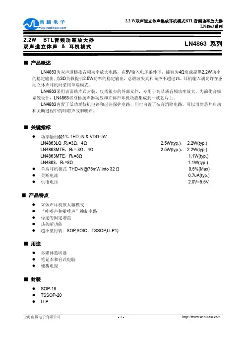
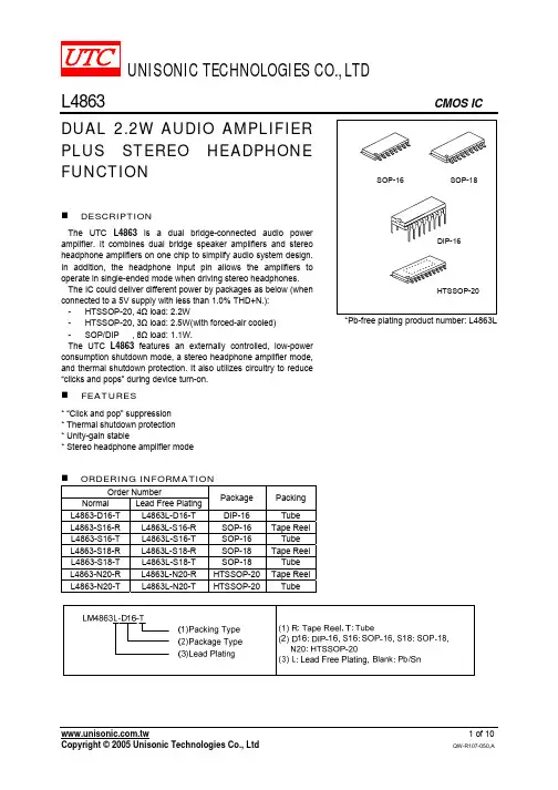
LM48611.1W Audio Power Amplifier with Shutdown ModeGeneral DescriptionThe LM4861is a bridge-connected audio power amplifier capable of delivering 1.1W of continuous average power to an 8Ωload with 1%THD+N using a 5V power supply.Boomer audio power amplifiers were designed specifically to provide high quality output power with a minimal amount of external components using surface mount packaging.Since the LM4861does not require output coupling capacitors,bootstrap capacitors,or snubber networks,it is optimally suited for low-power portable systems.The LM4861features an externally controlled,low-power consumption shutdown mode,as well as an internal thermal shutdown protection mechanism.The unity-gain stable LM4861can be configured by external gain-setting resistors for differential gains of up to 10without the use of external compensation components.Higher gains may be achieved with suitable compensation.Key Specificationsj THD+N for 1kHz at 1W continuousaverage output power into 8Ω1.0%(max)j Output power at 10%THD+Nat 1kHz into 8Ω1.5W (typ)j Shutdown Current0.6µA (typ)Featuresn No output coupling capacitors,bootstrap capacitors,or snubber circuits are necessary n Small Outline (SO)packagingn Compatible with PC power supplies n Thermal shutdown protection circuitry n Unity-gain stablen External gain configuration capabilityApplicationsn Personal computersn Portable consumer products n Self-powered speakers nToys and gamesConnection DiagramSmall Outline Package01198602Top ViewOrder Number LM4861M See NS Package Number M08ABoomer ®is a registered trademark of National Semiconductor Corporation.February 2003LM48611.1W Audio Power Amplifier with Shutdown Mode©2003National Semiconductor Corporation Typical Application01198601FIGURE 1.Typical Audio Amplifier Application CircuitL M 4861 2Absolute Maximum Ratings(Note2) If Military/Aerospace specified devices are required, please contact the National Semiconductor Sales Office/ Distributors for availability and specifications.Supply Voltage 6.0V Storage Temperature−65˚C to+150˚C Input Voltage−0.3V to V DD+0.3V Power Dissipation(Note3)Internally limited ESD Susceptibility(Note4)3000V ESD Susceptibility(Note5)250V Junction Temperature150˚C Soldering InformationSmall Outline PackageVapor Phase(60sec.) Infrared(15sec.)215˚C220˚CSee AN-450“Surface Mounting and their Effects onProduct Reliability”for other methods of soldering surfacemount devices.Operating RatingsTemperature RangeT MIN≤T A≤T MAX−40˚C≤T A≤+85˚C Supply Voltage 2.0V≤V DD≤5.5VThermal ResistanceθJC(typ)—M08A35˚C/WθJA(typ)—M08A140˚C/WθJC(typ)—N08E37˚C/WθJA(typ)—N08E107˚C/WElectrical Characteristics(Note1)(Note2)The following specifications apply for V DD=5V,unless otherwise specified.Limits apply for T A=25˚C.Symbol Parameter ConditionsLM4861Units(Limits) Typical Limit(Note6)(Note7)V DD Supply Voltage 2.0V(min)5.5V(max)I DD Quiescent Power Supply Current V IN=0V,I O=0A(Note8) 6.510.0mA(max)I SD Shutdown Current V pin1=V DD0.610.0µA(max)V OS Output Offset Voltage V IN=0V 5.050.0mV(max)P O Output Power THD=1%(max);f=1kHz 1.1 1.0W(min)THD+N Total Harmonic Distortion+Noise P O=1Wrms;20Hz≤f≤20kHz0.72%PSRR Power Supply Rejection Ratio V DD=4.9V to5.1V65dBNote1:All voltages are measured with respect to the ground pin,unless otherwise specified.Note2:Absolute Maximum Ratings indicate limits beyond which damage to the device may occur.Operating Ratings indicate conditions for which the device is functional,but do not guarantee specific performance limits.Electrical Characteristics state DC and AC electrical specifications under particular test conditions which guarantee specific performance limits.This assumes that the device is within the Operating Ratings.Specifications are not guaranteed for parameters where no limitis given,however,the typical value is a good indication of device performance.Note3:The maximum power dissipation must be derated at elevated temperatures and is dictated by T JMAX,θJA,and the ambient temperature T A.The maximum allowable power dissipation is P DMAX=(T JMAX−T A)/θJA or the number given in the Absolute Maximum Ratings,whichever is lower.For the LM4861,T JMAX=150˚C,and the typical junction-to-ambient thermal resistance,when board mounted,is140˚C/W.Note4:Human body model,100pF discharged through a1.5kΩresistor.Note5:Machine Model,220pF–240pF discharged through all pins.Note6:Typicals are measured at25˚C and represent the parametric norm.Note7:Limits are guaranteed to Nationai’s AOQL(Average Outgoing Quality Level).Note8:The quiescent power supply current depends on the offset voltage when a practical load is connected to the amplifier.LM48613High Gain Application CircuitSingle Ended Application Circuit01198603FIGURE 2.Audio Ampiifier with A VD =2001198604*C S and C B size depend on specific application requirements and constraints.Typical vaiues of C S and C B are 0.1µF.**Pin 1should be connected to V DD to disable the amplifier or to GND to enable the amplifier.This pin should not be left floating.***These components create a “dummy”load for pin 8for stability purposes.FIGURE 3.Single-Ended Amplifier with A V =−1L M 4861 4External Components Description(Figures 1,2)Components Functional Description1.R i Inverting input resistance which sets the closed-loop gain in conjunction with R f .This resistor also forms a high pass filter with C i at f C =1/(2πR i C i ).2.C i Input coupling capacitor which blocks DC voltage at the amplifier’s input terminals.Also creates a highpass filter with R i at f C =1/(2πR i C i ).3.R f Feedback resistance which sets closed-loop gain in conjunction with R i .4.C S Supply bypass capacitor which provides power supply filtering.Refer to the Application Information section for proper placement and selection of supply bypass capacitor.5.C BBypass pin capacitor which provides half supply filtering.Refer to the Application Information section for proper placement and selection of bypass capacitor.6.C f (Note 9)C f in conjunction with R f creates a low-pass filter which bandwidth limits the amplifier and prevents possible high frequency oscillation bursts.f C =1/(2πR f C f )Note 9:Optional component dependent upon specific design requirements.Refer to the Application Information section for more information.Typical Performance CharacteristicsTHD+N vs FrequencyTHD+N vs Frequency0119860501198606THD+N vs Frequency THD+N vs Output Power0119860701198609LM48615Typical Performance Characteristics(Continued)THD+N vs Output PowerOutput Power vs Load Resistance0119861001198617Output Power vs Supply Voltage Power Dissipation vsOutput Power0119861801198616Noise Floor vs FrequencySupply Current Distributionvs Temperature0119861401198615L M 4861 6Typical Performance Characteristics(Continued)Supply Current vsSupply Voltage Power Derating Curve0119861201198613Power Supply Rejection RatioOpen LoopFrequency Response0119862001198619LM4861 7Application InformationBRIDGE CONFIGURATION EXPLANATIONAs shown in Figure 1,the LM4861has two operational amplifiers internally,allowing for a few different amplifier configurations.The first amplifier’s gain is externally config-urable,while the second amplifier is internally fixed in a unity-gain,inverting configuration.The closed-loop gain of the first amplifier is set by selecting the ratio of R f to R i while the second amplifier’s gain is fixed by the two internal 40k Ωresistors.Figure 1shows that the output of amplifier one serves as the input to amplifier two which results in both amplifiers producing signals identical in magnitude,but out of phase 180˚.Consequently,the differential gain for the IC is:A vd =2*(R f /R i )By driving the load differentially through outputs V O1and V O2,an amplifier configuration commonly referred to as “bridged mode”is established.Bridged mode operation is different from the classical single-ended amplifier configura-tion where one side of its load is connected to ground.A bridge amplifier design has a few distinct advantages over the single-ended configuration,as it provides differential drive to the load,thus doubling output swing for a specified supply voltage.Consequently,four times the output power is possible as compared to a single-ended amplifier under the same conditions.This increase in attainable output power assumes that the amplifier is not current limited or clipped.In order to choose an amplifier’s closed-loop gain without caus-ing excessive clipping which will damage high frequency transducers used in loudspeaker systems,please refer to the Audio Power Amplifier Design section.A bridge configuration,such as the one used in Boomer Audio Power Amplifiers,also creates a second advantage over single-ended amplifiers.Since the differential outputs,V O1and V O2,are biased at half-supply,no net DC voltage exists across the load.This eliminates the need for an output coupling capacitor which is required in a single supply,single-ended amplifier configuration.Without an output cou-pling capacitor in a single supply,single-ended amplifier,the half-supply bias across the load would result in both in-creased internal IC power dissipation and also permanent loudspeaker damage.An output coupling capacitor forms a high pass filter with the load requiring that a large value such as 470µF be used with an 8Ωload to preserve low frequency response.This combination does not produce a flat re-sponse down to 20Hz,but does offer a compromise between printed circuit board size and system cost,versus low fre-quency response.POWER DISSIPATIONPower dissipation is a major concern when designing a successful amplifier,whether the amplifier is bridged or single-ended.A direct consequence of the increased power delivered to the load by a bridge amplifier is an increase in internal power dissipation.Equation 1states the maximum power dissipation point for a bridge amplifier operating at a given supply voltage and driving a specified output load.P DMAX =4*(V DD )2/(2π2R L )(1)Since the LM4861has two operational amplifiers in one package,the maximum internal power dissipation is 4times that of a single-ended amplifier.Even with this substantial increase in power dissipation,the LM4861does not require heatsinking.From Equation 1,assuming a 5V power supply and an 8Ωload,the maximum power dissipation point is625mW.The maximum power dissipation point obtained from Equation 1must not be greater than the power dissipation that results from Equation 2:P DMAX =(T JMAX −T A )/θJA(2)For the LM4861surface mount package,θJA =140˚C/W and T JMAX =150˚C.Depending on the ambient temperature,T A ,of the system surroundings,Equation 2can be used to find the maximum internal power dissipation supported by the IC packaging.If the result of Equation 1is greater than that of Equation 2,then either the supply voltage must be de-creased or the load impedance increased.For the typical application of a 5V power supply,with an 8Ωload,the maximum ambient temperature possible without violating the maximum junction temperature is approximately 62.5˚C pro-vided that device operation is around the maximum power dissipation point.Power dissipation is a function of output power and thus,if typical operation is not around the maxi-mum power dissipation point,the ambient temperature can be increased.Refer to the Typical Performance Charac-teristics curves for power dissipation information for lower output powers.POWER SUPPLY BYPASSINGAs with any power amplifier,proper supply bypassing is critical for low noise performance and high power supply rejection.The capacitor location on both the bypass and power supply pins should be as close to the device as possible.As displayed in the Typical Performance Charac-teristics section,the effect of a larger half supply bypass capacitor is improved low frequency THD+N due to in-creased half-supply stability.Typical applications employ a 5V regulator with 10µF and a 0.1µF bypass capacitors which aid in supply stability,but do not eliminate the need for bypassing the supply nodes of the LM4861.The selection of bypass capacitors,especially C B ,is thus dependant upon desired low frequency THD+N,system cost,and size con-straints.SHUTDOWN FUNCTIONIn order to reduce power consumption while not in use,the LM4861contains a shutdown pin to externally turn off the amplifier’s bias circuitry.The shutdown feature turns the amplifier off when a logic high is placed on the shutdown pin.Upon going into shutdown,the output is immediately discon-nected from the speaker.A typical quiescent current of 0.6µA results when the supply voltage is applied to the shutdown pin.In many applications,a microcontroller or microproces-sor output is used to control the shutdown circuitry which provides a quick,smooth transition into shutdown.Another solution is to use a single-pole,single-throw switch that when closed,is connected to ground and enables the am-plifier.If the switch is open,then a soft pull-up resistor of 47k Ωwill disable the LM4861.There are no soft pull-down resistors inside the LM4861,so a definite shutdown pin voltage must be applied externally,or the internal logic gate will be left floating which could disable the amplifier unex-pectedly.HIGHER GAIN AUDIO AMPLIFIERThe LM4861is unity-gain stable and requires no external components besides gain-setting resistors,an input coupling capacitor,and proper supply bypassing in the typical appli-cation.However,if a closed-loop differential gain of greater than 10is required,a feedback capacitor may be needed,as shown in Figure 2,to bandwidth limit the amplifier.This feedback capacitor creates a low pass filter that eliminatesL M 48618Application Information(Continued)possible high frequency oscillations.Care should be taken when calculating the −3dB frequency in that an incorrect combination of R f and C f will cause rolloff before 20kHz.A typical combination of feedback resistor and capacitor that will not produce audio band high frequency rolloff is R f =100k Ωand C f =5pF.These components result in a −3dB point of approximately 320kHz.Once the differential gain of the amplifier has been calculated,a choice of R f will result,and C f can then be calculated from the formula stated in the External Components Description section.VOICE-BAND AUDIO AMPLIFIERMany applications,such as telephony,only require a voice-band frequency response.Such an application usually re-quires a flat frequency response from 300Hz to 3.5kHz.By adjusting the component values of Figure 2,this common application requirement can be implemented.The combina-tion of R i and C i form a highpass filter while R f and C f form a lowpass ing the typical voice-band frequency range,with a passband differential gain of approximately 100,the following values of R i ,C i ,R f ,and C f follow from the equa-tions stated in the External Components Description sec-tion.R i =10k Ω,R f =510k ,C i =0.22µF,and C f =15pFFive times away from a −3dB point is 0.17dB down from the flatband response.With this selection of components,the resulting −3dB points,f L and f H ,are 72Hz and 20kHz,re-spectively,resulting in a flatband frequency response of better than ±0.25dB with a rolloff of 6dB/octave outside of the passband.If a steeper rolloff is required,other common bandpass filtering techniques can be used to achieve higher order filters.SINGLE-ENDED AUDIO AMPLIFIERAlthough the typical application for the LM4861is a bridged monoaural amp,it can also be used to drive a load single-endedly in applications,such as PC cards,which require that one side of the load is tied to ground.Figure 3shows a common single-ended application,where V O1is used to drive the speaker.This output is coupled through a 470µF capacitor,which blocks the half-supply DC bias that exists in all single-supply amplifier configurations.This capacitor,designated C O in Figure 3,in conjunction with R L ,forms a highpass filter.The −3dB point of this high pass filter is 1/(2πR L C O ),so care should be taken to make sure that the product of R L and C O is large enough to pass low frequen-cies to the load.When driving an 8Ωload,and if a full audio spectrum reproduction is required,C O should be at least 470µF.V O2,the output that is not used,is connected through a 0.1µF capacitor to a 2k Ωload to prevent instability.While such an instability will not affect the waveform of V O1,it is good design practice to load the second output.AUDIO POWER AMPLIFIER DESIGN Design a 1W /8ΩAudio Amplifier Given:Power Output 1WrmsLoad Impedance 8ΩInput Level 1Vrms Input Impedance 20k ΩBandwidth100Hz–20kHz ±0.25dBA designer must first determine the needed supply rail to obtain the specified output power.By extrapolating from the Output Power vs Supply Voltage graph in the Typical Per-formance Characteristics section,the supply rail can be easily found.A second way to determine the minimum sup-ply rail is to calculate the required V opeak using Equation 3and add the dropout ing this method,the mini-mum supply voltage would be (V opeak +V OD ,where V OD is typically 0.6V.(3)For 1W of output power into an 8Ωload,the required V opeak is 4.0V.A minumum supply rail of 4.6V results from adding V opeak and V od .But 4.6V is not a standard voltage that exists in many applications and for this reason,a supply rail of 5V is designated.Extra supply voltage creates dynamic head-room that allows the LM4861to reproduce peaks in excess of 1Wwithout clipping the signal.At this time,the designer must make sure that the power supply choice along with the output impedance does not violate the conditions explained in the Power Dissipation section.Once the power dissipation equations have been addressed,the required differential gain can be determined from Equa-tion 4.(4)R f /R i =A VD /2(5)From equation 4,the minimum A vd is 2.83:A vd =3Since the desired input impedance was 20k Ω,and with a A vd of 3,a ratio of 1:1.5of R f to R i results in an allocation of R i =20k Ω,R f =30k Ω.The final design step is to address the bandwidth requirements which must be stated as a pair of −3dB frequency points.Five times away from a −3db point is 0.17dB down from passband response which is better than the required ±0.25dB specified.This fact results in a low and high frequency pole of 20Hz and 100kHz respectively.As stated in the External Components section,R i in conjunc-tion with C i create a highpass filter.C i ≥1/(2π*20k Ω*20Hz)=0.397µF;use 0.39µF.The high frequency pole is determined by the product of the desired high frequency pole,f H ,and the differential gain,A vd .With a A vd =2and f H =100kHz,the resulting GBWP =100kHz which is much smaller than the LM4861GBWP of 4MHz.This figure displays that if a designer has a need to design an amplifier with a higher differential gain,the LM4861can still be used without running into bandwidth problems.LM48619LM4861MDA MWA1.1W Audio Power Amplifier with Shutdown Mode01198626Die Layout (B -Step)DIE/WAFER CHARACTERISTICSFabrication AttributesGeneral Die InformationPhysical Die Identification LM4861B Bond Pad Opening Size (min)83µm x 83µm Die StepB Bond Pad Metalization ALUMINUM Physical AttributesPassivation VOM NITRIDE Wafer Diameter 150mmBack Side Metal BARE BACK Dise Size (Drawn)1372µm x 2032µm 54.0mils x 80.0mils Back Side ConnectionGNDThickness 406µm Nominal Min Pitch108µm NominalSpecial Assembly Requirements:Note:Actual die size is rounded to the nearest micron.Die Bond Pad Coordinate Locations (B -Step)(Referenced to die center,coordinates in µm)NC =No Connection,N.U.=Not UsedSIGNAL NAME PAD#NUMBERX/Y COORDINATES PAD SIZEX Y X Y SHUTDOWN 1-42571083x 83BYPASS 2-44549983x 83NC 3-445-3483x 170NC 4-445-38383x 83INPUT +5-445-49283x 83INPUT -6-352-71083x 83GND 7-243-71083x 83Vo18-91-710170x 83GND 9445-57483x 170VDD 10445-283x 170NC 1144538783x 83GND 1244563383x 170Vo213-63710170x 83GND14-21571083x83L M 486110LM4861 LM4861MDA MWA1.1W Audio Power Amplifier with Shutdown Mode(Continued)IN U.S.ATel#:1877Dial Die187********Fax:12075416140IN EUROPETel:49(0)8141351492/1495Fax:49(0)8141351470IN ASIA PACIFICTel:(852)27371701IN JAPANTel:81043299230811Physical Dimensionsinches (millimeters)unless otherwise noted8-Lead (0.150"Wide)Molded Small Outllne Package,JEDEC (M)Order Number LM4861NS Package Number M08ALIFE SUPPORT POLICYNATIONAL’S PRODUCTS ARE NOT AUTHORIZED FOR USE AS CRITICAL COMPONENTS IN LIFE SUPPORT DEVICES OR SYSTEMS WITHOUT THE EXPRESS WRITTEN APPROVAL OF THE PRESIDENT AND GENERAL COUNSEL OF NATIONAL SEMICONDUCTOR CORPORATION.As used herein:1.Life support devices or systems are devices or systems which,(a)are intended for surgical implant into the body,or (b)support or sustain life,and whose failure to perform when properly used in accordance with instructions for use provided in the labeling,can be reasonably expected to result in a significant injury to the user.2.A critical component is any component of a life support device or system whose failure to perform can be reasonably expected to cause the failure of the life support device or system,or to affect its safety or effectiveness.National Semiconductor Americas Customer Support CenterEmail:new.feedback@ Tel:1-800-272-9959National SemiconductorEurope Customer Support CenterFax:+49(0)180-5308586Email:europe.support@Deutsch Tel:+49(0)6995086208English Tel:+44(0)8702402171Français Tel:+33(0)141918790National Semiconductor Asia Pacific Customer Support Center Fax:65-62504466Email:ap.support@ Tel:65-62544466National SemiconductorJapan Customer Support Center Fax:81-3-5639-7507Email:nsj.crc@ Tel:81-3-5639-7560L M 48611.1W A u d i o P o w e r A m p l i f i e r w i t h S h u t d o w n M o d eNational does not assume any responsibility for use of any circuitry described,no circuit patent licenses are implied and National reserves the right at any time without notice to change said circuitry and specifications.。