欧姆龙轻触式开关说明
- 格式:ppt
- 大小:1.17 MB
- 文档页数:15
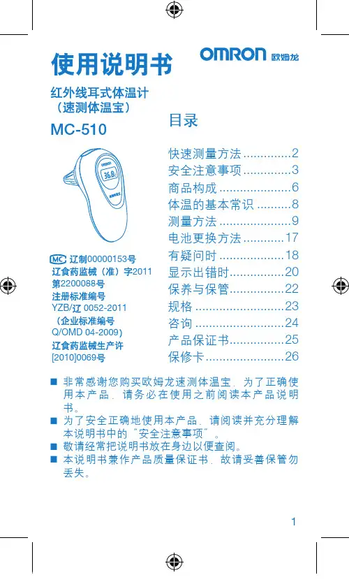
1MC-510目录快速测量方法 (2)安全注意事项 (3)商品构成 (6)体温的基本常识 (8)测量方法 (9)电池更换方法 (17)有疑问时 (18)显示出错时 ................20保养与保管 ................22规格 ..........................23咨询 .. (24)产品保证书 (25)保修卡 .......................26非常感谢您购买欧姆龙速测体温宝,为了正确使 ⏹用本产品,请务必在使用之前阅读本产品说明书。
为了安全正确地使用本产品,请阅读并充分理解 ⏹本说明书中的“安全注意事项”。
敬请经常把说明书放在身边以便查阅。
⏹本说明书兼作产品质量保证书,故请妥善保管勿 ⏹丢失。
快速测量方法3说明书中所表示的警告记号和警告图例,其目的 ⏹是为了使您能够安全、正确地使用本产品,并防止对您及他人造成伤害。
警告记号、图例及其含义如下:⏹※ 所谓物品损坏是指有关房屋、家产及家畜、宠物的损害。
安全注意事项45建议• 当您把所测体温告诉医生时,请说明您是用耳式体温计进行测量的。
• 请不要用于人体耳部以外的体温测量。
• 请不要强行碰撞、摔落、踩踏和摇动本体。
•请勿在测量过程中在体温计附近使用移动电话。
• 请勿拆卸、修理和改造本体。
• 本产品不防水。
请注意不要让液体(酒精、水滴、热水等)进入本体内部。
6☆ 探测器保护罩是消耗品,使用完结后请购买新的探测器保护罩。
☆ 探测器保护罩脏污破损时,请更换探测器保护罩,因为表面的脏污和破损会影响测量精度。
78体温的基本常识测量腋下和舌下的体温易受外界温度、汗水和唾液等的影响,所以较之所测的温度偏低,而测量耳温可更好地反映脑部温度,快速测得正确的体温值。
为了正确判断发烧的状态,请了解正常情况下家庭成员的耳温。
耳温和腋下温度分布了解家庭成员正常状态时耳温。
耳温与腋下温度存在差异,通过正常状态时耳部与腋下的「温度差」可以大致比较出发烧时的「温度差」。
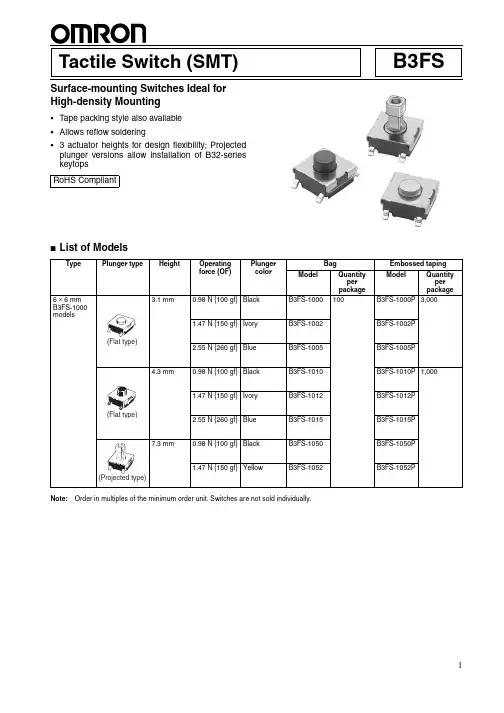
B3FSTactile Switch (SMT)Surface-mounting Switches Ideal for High-density Mounting•Tape packing style also available •Allows reflow soldering• 3 actuator heights for design flexibility; Projected plunger versions allow installation of B32-series keytops ■List of ModelsNote:Order in multiples of the minimum order unit. Switches are not sold individually.RoHS CompliantTypePlunger typeHeightOperating force (OF)Plunger colorBagEmbossed taping ModelQuantity per package ModelQuantity per package6 × 6 mm B3FS-1000 models3.1 mm 0.98 N {100 gf}Black B3FS-1000100B3FS-1000P 3,0001.47 N {150 gf}IvoryB3FS-1002B3FS-1002P 2.55 N {260 gf}BlueB3FS-1005B3FS-1005P 4.3 mm0.98 N {100 gf}Black B3FS-1010B3FS-1010P 1,0001.47 N {150 gf}IvoryB3FS-1012B3FS-1012P 2.55 N {260 gf}BlueB3FS-1015B3FS-1015P 7.3 mm0.98 N {100 gf}Black B3FS-1050B3FS-1050P 1.47 N {150 gf}YellowB3FS-1052B3FS-1052P(Flat type)(Flat type)(Projected type)■Ratings/Characteristics■Operating CharacteristicsRatings1 to 50 mA, 5 to 24 VDC (resistive load)Ambient operating temperature -25°C to +70°C at 60%RH max. (with no icing or condensation)Ambient operating humidity 35% to 85% (at +5 to +35°C)Contact form SPST-NOContact resistance 100 m Ω max. (initial value) (rated: 1 mA, 5 VDC)Insulation resistance 100 M Ω min. (at 100 VDC)Dielectric strength 250 VAC, 50/60 Hz for 1 min Bounce time 5 ms max.Vibration resistance Malfunction: 10 to 55 Hz, 1.5-mm double amplitude Shock resistance Destruction: 1,000 m/s 2 {approx. 100G} max. Malfunction: 100 m/s 2 {approx. 10G} max.DurabilityStandard models (0.98 N {100 gf}): 1,000,000 operations min. High-force models (1.47 N {150 gf}): 300,000 operations min. High-force models (2.55 N {260 gf}): 100,000 operations min.Weight B3FS-1000: Approx. 0.2 gB3FS-1000Item0.98 N 1.47 N 2.55 N Operating force (OF)0.98±0.29 N {100±30 gf} 1.47±0.49 N {150±50 gf}2.55±0.69 N {260±70 gf}Releasing force (RF)0.2 N {20 gf} min.0.49 N {50 gf} min.0.49 N {50 gf} min.Pretravel (PT)0.25 +0.2/−0.1 mm■Dimensions (Unit: mm)Note:The numbers used for terminals in the following graphics are indicated in the “Bottom View” diagram below. In this diagram, the Switch is rotated so that the terminals are on the right and left-hand sides, and the OMRON logo appears the right way up.Note:Unless otherwise specified, a tolerance of ±0.4 mm applies to all dimensions. No terminal numbers are indicated on the Switches.■Key Tops B32-series Special Key Tops are available for projected plunger models. Refer to the Datasheet of B32 for details.■PrecautionsBe sure to read the safety precautions common to all Tactile Switches for correct use.。
欧姆龙光电开关手册
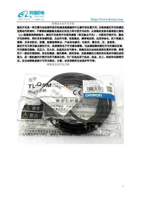
接近开关是一种无需与运动部件进行机械直接接触而可以操作的位置开关,当物体接近开关的感应面到动作距离时,不需要机械接触及施加任何压力即可使开关动作,从而驱动直流电器或给计算机(plc)装置提供控制指令。
接近开关是种开关型传感器(即无触点开关),它既有行程开关、微动开关的特性,同时具有传感性能,且动作可靠,性能稳定,频率响应快,应用寿命长,抗干扰能力强等、并具有防水、防震、耐腐蚀等特点。
产品有电感式、电容式、霍尔式、交、直流型。
接近开关又称无触点接近开关,是理想的电子开关量传感器。
当金属检测体接近开关的感应区域,开关就能无接触,无压力、无火花、迅速发出电气指令,准确反应出运动机构的位置和行程,即使用于一般的行程控制,其定位精度、操作频率、使用寿命、安装调整的方便性和对恶劣环境的适用能力,是一般机械式行程开关所不能相比的。
它广泛地应用于机床、冶金、化工、轻纺和印刷等行业。
在自动控制系统中可作为限位、计数、定位控制和自动保护环节等。
欧姆龙光电开关手册。
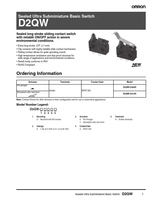
Sealed long stroke sliding contact switch with reliable ON/OFF action in severe environmental conditions.•Extra-long stroke. (OT: 2.7 mm)•Clip contacts with highly reliable slide contact mechanism.•Sliding contact allows for quiet operating sound.•High temperature resistance and drip-proof structure for wide range of applications and environmental conditions.•Switch body conforms to IP67•RoHS CompliantOrdering InformationNote:Contact Omron for other terminal or lever configuration and for use in automotive applications. Model Number Legend:Specifications■ CharacteristicsNote:1.Data shown are of initial value.2.For pin plunger models, the above values apply for use at the free position, operating position, and total travel position. For models withlevers, the values apply at the total travel position.■RatingsNote:The resistive load ratings apply under the following test conditions: Ambient T emperature = 20±2°C,Ambient Humidity = 65±5%,Operating frequency = 30 operations/min.■Contact SpecificationsNote:Minimum applicable loads are indicated by N standard refer-ence values. This value represents the failure rate at a 60% (λ60) reliability level (JIS C5003).The equation λ60=0.5 x 10⁻⁶ / operations indicates that a failure rate of 1/2,000,000 operations can be expected at a reliability level of 60%Item SpecificationOperating speed 1 mm to 500 m/sOperating frequency30 operations/minInsulation resistance100 MΩ min. (at 500 V DC)Contact resistance100 mΩ max.Dielectric strength600 V AC, 50/60 Hz for 1 min between terminals of the same polarity1,500 V AC, 50/60 Hz for 1 min between current-carrying metal parts and ground, andbetween each terminal and non-current-carrying metal partsVibration resistance (See note 2)Malfunction: 10 to 55 Hz, 1.5-mm double amplitudeShock resistance (See note 2)Destruction: 1,000 m/s2 max.Malfunction: 300 m/s2 max.Ambient operating temperature–40 to 85 °C (with no icing)Ambient operating humidity95% max. (for 5 to 35°C)Degree of protection IEC IP67 (excluding the terminals on terminal models)Degree of protection against electric shock Class IProof tracking index (PTI)175Life expectancy Mechanical(30 operations/min)500,000 operations min.Electrical(20 operations/min)200,000 operations min. (at 30 V DC 0.1 A) 500,000operations min. (at 14 V DC 10 mA)Weight Approx. 0.7 g (for pin plunger models with terminals) Rated voltage (V)Resistive load30 V DC 14 V DC 0.1 A10 mAItem SpecificationSpecification SlideMaterial Gold platedMinimum applicable load(reference value)1 mA at 5 V DCEngineering Data■Mounting Structure and Reference Positions for Operating CharacteristicsNote:1.All units are in millimeters unless otherwise indicated.■TerminalsTerminal (H)■Contact FormSPST-NODimensions and Operating CharacteristicsNote:1.All units are in millimeters unless otherwise indicated.Mounting Hole Dimensions (Reference)Pin Plunger ModelsCharacteristic Models with posts OF max. 1.5 N {153 gf}OT ref.(2.7 mm)FP max.OPTTP max.9.2 mm 8.4±0.3 mm 5.9 mmSimulated Roller Leaf Lever ModelsD2QW-C073HCharacteristic Models with posts OF max. 1.5 N {153 gf}OT ref.(3.5 mm)FP max.OPTTP max.14.4 mm 12.0±0.5 mm 8.7 mmPrecautionsBe sure to read the precautions and information common to all Snap Action and Detection Switches, contained in the T echnical User’s Guide, “Snap Action Switches, T echnical Information” for correct use.■CautionsDegree of ProtectionIEC Publication 529, degree of protection IP67.Do not use this product in water. Although molded lead wire models satisfy the test conditions for the standard given above, this test is to check the ingress of water into the switch enclosure after submerging the Switch in water for a given time. Satisfying this test condition does not mean that the Switch can be used in water.Do not operate the Switch when it is exposed to water spray, or when water drops adhere to the Switch surface, or during sudden tempera-ture changes, otherwise water may intrude into the interior of the Switch due to a suction effect.Prevent the Switch from coming into contact with oil and chemicals. Otherwise, damage to or deterioration of Switch materials may result.Do not use the Switch in areas where it is exposed to silicon adhesives, oil, or grease, otherwise faulty contact may result due to the generation of silicon oxide.SolderingWhen soldering the lead wire to the terminal, first insert the lead wire conductor through the terminal hole and then conduct soldering. Complete soldering within 3 s using a soldering iron with a capacity of 50 W max. and a tip temperature of 300 °C max.Also, do not apply an external force to the Switch for 1 minute after the completion of soldering.Improper soldering involving an excessively high temperature or excessive soldering time may deteriorate the characteristics of the Switch.When using automatic soldering, solder at at 260 °C max and com-plete soldering with 5 seconds.Side-actuated (Cam/Dog) OperationWhen using a cam or dog to operate the Switch, factors such as the operating speed, operating frequency, push-button indentation, and material and shape of the cam or dog will affect the durability of the Switch. Confirm performance specifications under actual operation conditions before using the Switch in applications.■Correct UseMountingT urn OFF the power supply before mounting or removing the Switch, wiring, or performing maintenance or inspection. Failure to do so may result in electric shock or burning.For M3-screw mounting models, use M3 mounting screws with plane washers or spring washers to securely mount the Switch. Tighten the screws to a torque of 0.29 N·m {3 kgf·cm}. Exceeding the specified torque may result in deterioration of the sealing or damage.For models with posts, secure the posts by thermal caulking or by pressing into an attached device. When pressed into an attached device, provide guides on the opposite ends of the posts to ensure that they do not fall out or rattle.Mount the Switch onto a flat surface. Mounting on an uneven surface may cause deformation of the Switch, resulting in faulty operation or damage.Operating BodyUse an operating body with low frictional resistance and of a shape that will not interfere with the sealing rubber, otherwise the plunger may be damaged or the sealing may deteriorate.HandlingDo not handle the Switch in a way that may cause damage to the sealing rubber.When handling the Switch, ensure that pressure is not applied to the posts in the directions shown in the following diagram. Also, ensure that uneven pressure or pressure in a direction other than the operat-ing direction is not applied to the Actuator as shown in the following diagram. Otherwise, the post, Actuator, or Switch may be damaged, or the service life may be reduced.Wiring Molded Lead Wire ModelsWhen wiring molded lead wire models, ensure that there is no weight on the wire or that there are no sharp bends near the parts where the wire is drawn out. Otherwise, damage to the Switch or deterioration in the sealing may result.Using Micro LoadsEven when using micro load models within the operating range, inrush currents or surges may decrease the life expectancy of the Switch. Therefore, insert a contact protection circuit where neces-sary.MEMOOMRON ON-LINEGlobal - USA - Cat. No. B117-E-01Printed in USAOMRON ELECTRONIC COMPONENTS LLC55 E. Commerce Drive, Suite B Schaumburg, IL 60173847-882-228811/10 Specifications subject to change without noticeAll sales are subject to Omron Electronic Components LLC standard terms and conditions of sale, which can be found at /components/web/webfiles.nsf/sales_terms.html ALL DIMENSIONS SHOWN ARE IN MILLIMETERS.T o convert millimeters into inches, multiply by 0.03937. T o convert grams into ounces, multiply by 0.03527.。
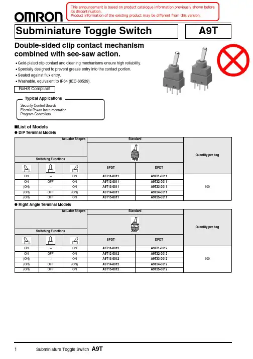
1Subminiature Toggle Switch A9TA9TSubminiature Toggle SwitchDouble-sided clip contact mechanism combined with see-saw action.•Gold-plated clip contact and cleaning mechanisms ensure high reliability.•Specially designed to prevent grease entry into the contact portion.•Sealed against flux entry.•Washable, equivalent to IP64 (IEC-60529).■List of Models●DIP Terminal Models●Right Angle Terminal ModelsRoHS CompliantSecurity Control BoardsElectric Power Instrumentation Program ControllersTypical ApplicationsSubminiature Toggle Switch A9T2●Vertical Mount Terminal ModelsNote:1.(ON) shows Momentary.2.Switching Functions show the view from the side of Type and Brand name marking.3.Actuator does not stop at "-" position.■Ratings/CharacteristicsRatings50 mA at 60 VAC/DC, 1 μA (minimum current) at 20 mVAC/DC Ambient operating temperature -20 to +80 °C 60% RH max. (with no icing or condensation)Ambient operating humidity 45 to 85%RH (at +5 to +35 °C )Insulation resistance 1,000 M Ω min. (Initial value)Contact resistance 50 m Ω max. (Initial value)Dielectric strength 500 VAC for 1 min between terminals, between terminals and ground Vibration resistance Malfunction 10 to 55 Hz,1.5-mm double amplitude Shock resistance Malfunction 500 m/s 2 min.Durability Mechanical 50,000 operations min.Electrical50,000 operations min.Operating force0.49 to 3.43 N {50 to 350 gf}WeightDIP TerminalStandard: 0.8 g Right Angle Terminal Standard: 1 g Vertical Mount Terminal Standard: 1 g3Subminiature Toggle Switch A9T■Dimensions (Unit: mm)●DIP Terminal ModelsNote:No. (1) and (3) terminals in the SPDT models are dummys to support the Switch case.●Right Angle Terminal Models●Vertical Mount Terminal ModelsNote:Unless otherwise specified, a tolerance of ±0.4 mm applies to all dimensions.PCB Dimensions (Top View)■Switching Function / Internal ConnectionsNote:(ON) shows Momentary.■Safety PrecautionsBe sure to read the Safety precautions common to all PCB-mount Manual Switches for correct use.Subminiature Toggle Switch A9T4。
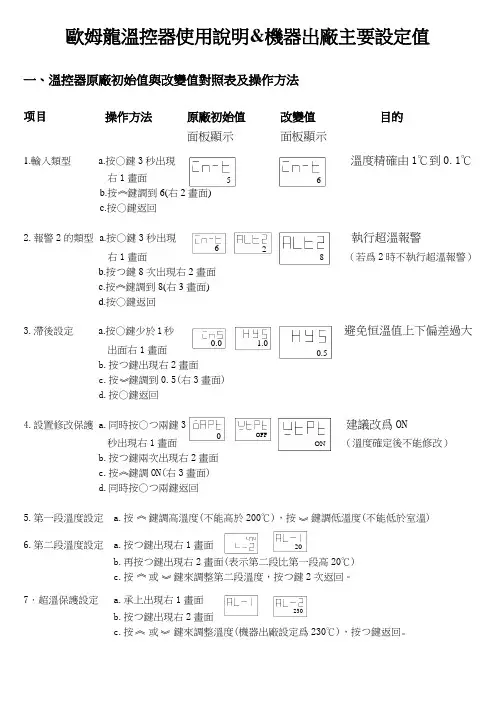
5 6 《 2 8 《 1.0 0.5 》 0 OFF《 《 》20 《 》230 《》6 ON 歐姆龍溫控器使用說明&機器出廠主要設定值一、溫控器原廠初始值與改變值對照表及操作方法项目 操作方法 原廠初始值 改變值 目的 面板顯示 面板顯示1.輸入類型a.按○鍵3秒出現 溫度精確由1℃到0.1℃ 右1畫面b.按 鍵調到6(右2畫面)c.按○鍵返回 2.報警2的類型 a.按○鍵3秒出現 執行超溫報警右1畫面 (若爲2時不執行超溫報警)b.按つ鍵8次出現右2畫面c.按 鍵調到8(右3畫面)d.按○鍵返回 3.滯後設定a.按○鍵少於1秒 避免恒溫值上下偏差過大出面右1畫面 b.按つ鍵出現右2畫面c.按 鍵調到0.5(右3畫面)d.按○鍵返回 4.設置修改保護 a.同時按○つ兩鍵3 建議改爲ON秒出現右1畫面 (溫度確定後不能修改)b.按つ鍵兩次出現右2畫面c.按 鍵調ON(右3畫面)d.同時按○つ兩鍵返回 5.第一段溫度設定 a.按 鍵調高溫度(不能高於200℃),按 鍵調低溫度(不能低於室溫) 6.第二段溫度設定 a.按つ鍵出現右1畫面b.再按つ鍵出現右2畫面(表示第二段比第一段高20℃)c.按 或 鍵來調整第二段溫度,按つ鍵2次返回。
7.超溫保護設定a.承上出現右1畫面b.按つ鍵出現右2畫面c.按 或 鍵來調整溫度(機器出廠設定爲230℃),按つ鍵返回。
0.0圖1 圖2 圖3 圖4 二、機器出廠主要設定值1.超溫保護a.數位溫控器230℃;b.液漲式溫度開關230℃。
2.恒溫設定a.第一段120℃;b.第二段140℃。
3.時間設定a.第一段時間60分鐘;b.第二段時間90分鐘;(第1個時間繼電器) (第2個時間繼電器)4.冷卻時間a.15分鐘(第3個時間繼電器) 5.溫度關機a.60℃(右邊的液漲式溫度開關)三.限時繼電器調設要領1.第一段時間設定——左邊a.通電啓動後,逆時針( )旋轉指針歸零(紅燈停止閃爍轉爲常亮,第二個限時繼電器啓動紅燈閃爍)b.若歸零的位置爲0再兩個刻度的位置(圖1)c.順時針( )旋轉指針到2的位置(圖2)d.逆時針( )旋轉指針到1再兩個刻度的位置(圖3)即可調到1小時±5分鐘的時間。
Standalone non-contact switches support applications like guarding doors or position monitoring in machines.They are using the proven Omron non-contact technology allowing to cover mechanical tolerances and vibrations.•Models with single or dual actuator available (For one or two door systems in e.g.)•Based on hall technology•Connect up to 20 switches in series •LED for easy diagnosis•Operates behind stainless steel fittings •Non-contact – no abrasion – no particles •Compensation of mechanical tolerances•Suitable for high pressure cleaning, CIP and SIP processes due IP69K (pre-wired types)•Conforms to safety categories up to PLe acc. EN ISO 13849-1Model number structure1. Housing Material:P:PlasticM:Stainless steel 2. Actuating type:A:Single actuator sensing D:Dual actuator sensing3. Cable length/connection05:5m cable 10:10m cableM1J8:M12 male connector, 8pin, fitted with 250mm cable**Only for Auto Start applicationsOrdering informationSwitchesPolyester housingStainless steel housingF3S-TGR-S @S @-@123TypeCable connection Order code Single actuator sensing5 m pre-wired F3S-TGR-SPSA-0510 m pre-wiredF3S-TGR-SPSA-10M12, 8pin fitted with 250mm cable *1*1only for Auto Start applicationsF3S-TGR-SPSA-M1J8Dual actuator sensing5 m pre-wired F3S-TGR-SPSD-0510 m pre-wiredF3S-TGR-SPSD-10M12, 8pin fitted with 250mm cable *1F3S-TGR-SPSD-M1J8TypeCable connection Order code Single actuator sensing5 m pre-wired F3S-TGR-SMSA-0510 m pre-wiredF3S-TGR-SMSA-10M12, 8pin fitted with 250mm cable *1F3S-TGR-SMSA-M1J8Dual actuator sensing5 m pre-wired F3S-TGR-SMSD-0510 m pre-wiredF3S-TGR-SMSD-10M12, 8pin fitted with 250mm cable *1*1only for Auto Start applicationsF3S-TGR-SMSD-M1J8F3S-TGR-S_A / F3S-TGR-S_D AccessoriesSpecifications Mechanical dataElectrical data Reliability Data Approved standards Order codeCables 8-pin 2m Y92E-M12PURSH8S2M-L 5m Y92E-M12PURSH8S5M-L 10m Y92E-M12PURSH8S10M-L 25m Y92E-M12PURSH8S25M-LActuators (only for master coded types)for F3S-TGR-SPSA and -SPSD F39-TGR-SPS-A for F3S-TGR-SMSA and -SMSD F39-TGR-SMS-AMounting screws Set of Torx safety screws(M4, 4×30mm, 4×20mm,4×10mm; incl. washers andTorx bit)F39-TGR-N-SCREWSItem Model Polyester Sensor Stainless steel sensorIndicator Green LED: Indication of safety circuits closed (Guard closed, actuator present, feedback circuit checked)Yellow LED: Indication of safety circuits open (Actuator removed)Operating distance OFF → ON (Sao)10 mm Close ON → OFF (Sar)15 mm OpenRec. setting gap5mmTolerance to misalignment5mm in any direction from 5mm setting gapActuator approach speed Min. 4 mm/s Max.1,000 mm/sOperating temperature–25 to 45°CEnclosure protection Flying lead IP69K M12 connector IP67Cable PVC, Ø 6mm o.d.Mounting bolts 2 × M4Tightening torque for mounting bolts Max. 1 NmShock resistance (IEC 68-2-27)11 ms, 30 gVibration resistance (IEC 68-2-6)10 to 55Hz, 1mmMaterial UL approved Polyester Stainless steel 316Item Model Polyester sensor Stainless steel sensor Sensing technology HallSerial connection up to 20 switchesPower supply24 VDC±10%Power consumption Max.0.1 ASwitching current Min.10 mA, 5 VDCRated loads Safety outputs Max.3A@24VDC Auxiliary output Max.0.5 A @ 24VDCEN ISO13849-1up to PLe depending upon system architecture EN 62061up to SIL3 depending upon system architecture PFHd 3.95 × 10⁻¹⁰Proof Test Interval (Life)20 yearsMTTFd446 yearsEN standards certified by TÜV RheinlandEN ISO13849-1EN 62061EN ISO14119EN 60204-1EN/IEC 60947-5-3UL 508, CSA C22.2BS 5304EN 1088 conformanceF3S-TGR-S_A / F3S-TGR-S_DDimensionsConnection diagramCable versionM1J8-Connector version (M12 male) - Only for Auto Start solutions385.504.404.404.405.505.507727S WITCHACTUATOR8495848495101042127+24 VDC NC Channel 1 (force guided relay)Reset/Check Circuit – Auto start Reset/Check Circuit – Output Aux. OutputNC Channel 2GNDNC Channel 1 (force guided relay)Reset/Check Circuit – Manual start NC Channel 2Signalb rown green white b l u e yellow pink grey redS ign a lWire (Y92E-M12PUR S H 8S _M-L)+24 VDC NC Ch a nnel 1 (force g u ided rel a y)Re s et/Check Circ u it – O u tp u tNC Ch a nnel 2GNDNC Ch a nnel 1 (force g u ided rel a y)Re s et/Check Circ u it – A u to s t a rt NC Ch a nnel 2F3S-TGR-S_A / F3S-TGR-S_DWiring examplesSerial connection (up to 20 switches) – Auto start PLe Cat4Two switches connected in series to give dual circuit safety outputs to machine contactors.Safety Circuit 1 (Black/White) utilises internally checked force guided relay contacts and is connected in series with the corresponding Safety Circuit 2 (Yellow/Green) of the next switch.Allows minimal wiring and higher current switching to K1 and K2 contactors.An automatic start with contactor feedback check is achieved by connecting K1 (Aux) and K2 (Aux) feedback contacts through Pink and Brown feedback check circuit.Serial connection (up to 20 switches) – Manual start PLe Cat4Two switches connected in series to give dual circuit safety outputs to machine contactors.Safety Circuit 1 (Black/White) utilises internally checked force guided relay contacts and is connected in series with the corresponding Safety Circuit 2 (Yellow/Green) of the next switch.Allows minimal wiring and higher current switching to K1 and K2 contactors.A manual start and contactor feedback check is achieved byconnecting K1 (Aux) and K2 (Aux) feedback contacts momentary start button through the Orange and Brown feedback check.GREYGREYGREYGREY•Be sure to wire each conductor correctly.•Be sure to confirm correct operation after completing mounting and adjustment.•Do not drop or attempt to disassemble the product.•Be sure to use the correct combination of switch and actuator.•Use a power supply of the specified voltage. Do not use power supplies with large ripples or power supplies that intermittently generate incorrect voltages.•Capacitors are consumable and require regular maintenance and inspection.Installation LocationsDo not install the product in the following locations. Doing so may result in product failure or malfunction.•Locations subject to direct sunlight•Locations subject to humidity levels outside the range 35% to 85%or subject to condensation due to extreme temperature changes •Locations subject to corrosive or flammable gases•Locations subject to shocks or vibration in excess of the product ratings•Locations subject to dust (including iron dust) or saltsTake appropiate and sufficient countermeasures when using the product in the following locations.•Locations subject to static electricity or other forms of noise •Locations subject to possible exposure to radioactivity •Locations subject to power supply lines•It is advisable to mount the switches on non ferrous materials. The presence of ferrous material can effect switching sensitivity.SolventsEnsure that solvents, such as alcohol, thinner, trichloroethane, or gasoline do not adhere to the product. Solvents may cause markings to fade and components to deteriorate.Mounting DirectionUsing for Hinged DoorsOn hinged doors, install the Sensor at an opening edge as shown below.Mutual InterferenceIf the switch and actuator are mounted in parallel, be sure to separate them by at least 25mm, as shown below.CORRECTINCORRECTCORRECTCORRECTF3S-TGR-S_A / F3S-TGR-S_DIn the interest of product improvement, specifications are subject to change without notice.ALL DIMENSIONS SHOWN ARE IN MILLIMETERS.To convert millimeters into inches, multiply by 0.03937. T o convert grams into ounces, multiply by 0.03527.Cat. No. F15E-EN-02A。
接近开关又称为无触点行程开关,它除了可以完成行程控制和限位保护外,还是一种非接触型的检测装置。
该产品具有工作可靠、寿命长、功耗低、复定位精度高以及操作频率高等优势特征。
并且,它能够在恶劣的环境中进行工作。
接近开关它既有行程开关、微动开关的特性,同时还具有传感性能。
该产品有电感式、电容式、霍尔式以及交直流型,从而它被广泛的应用于机床、冶金、化工、轻纺和印刷等行业。
并且,在自动控制系统中可作为限位、计数、定位控制和自动保护环节。
因此到目前为止,接近开关的应用范围日益广泛,其自身的发展和创新的速度也是极其迅速。
一、接近开关的主要功能1.检验距离检测电梯、升降设备的停止、起动、通过位置;检测车辆的位置,防止两物体相撞检测;检测工作机械的设定位置,移动机器或部件的极限位置;检测回转体的停止位置,阀门的开或关位置;检测气缸或液压缸内的活塞移动位置。
2.尺寸控制金属板冲剪的尺寸控制装置;自动选择、鉴别金属件长度;检测自动装卸时堆物高度;检测物品的长、宽、高和体积。
3.检测物体存在有否检测生产包装线上有无产品包装箱;检测有无产品零件。
4.转速与速度控制控制传送带的速度;控制旋转机械的转速;与各种脉冲发生器一起控制转速和转数。
5.检测异常检测瓶盖有无产品合格与不合格判断;检测包装盒内的金属制品缺乏与否;区分金属与非金属零件;产品有无标牌检测;起重机危险区报警;安全扶梯自动启停。
6.计量控制产品或零件的自动计量;检测计量器、仪表的指针范围而控制数或流量;检测浮标控制测面高度,流量;检测不锈钢桶中的铁浮标;仪表量程上限或下限的控制;流量控制,水平面控制。
二、接近开关的选型对于不同的材质的检测体和不同的检测距离,应选用不同类型的欧姆龙接近开关,以使其在系统中具有高的性能价格比,为此在选型中应遵循以下原则:1.当检测体为金属材料时,应选用高频振荡型欧姆龙接近开关,该类型欧姆龙接近开关对铁镍、A3钢类检测体检测最灵敏。
2.当检测体为非金属材料时,如木材、纸张、塑料、玻璃和水等,应选用电容型欧姆龙接近开关。
Joystick SwitchesQuality, reliability, precision Quality, reliability and precision are the hallmarks of our corporate philosophy.They represent concepts and values to which we feel totally committed. At EUCHNER, quality means that all our employees take personal respon-sibility for the company as a whole and, in particular, for their own field of work. This individual commitment to perfection results in products which are ideally tailored to the customers’needs and the requirements of the market. After all: our customers and their needs are the focus of all our efforts. Through efficient and effective use of resources, the promotion of personal initiative and courage in find-ing unusual solutions to the benefit of our customers, we ensure a high level of customer satisfaction. We familiar-ize ourselves with their needs, require-ments and products and we learn from the experiences of our cus-tomers’ own customers.EUCHNER – More than safety.Quality –made by EUCHNERMore than safety.Around the world –the Swabian specialists in motion sequence control for mechanical and sys-tems engineering.EUCHNER’s history began in 1940 with the establishment of an engineering office by Emil Euchner. Since that time, EUCHNER has been involved in the design and development of switch-gear for controlling a wide variety of motion sequences in mechanical and systems engineering. In 1953, Emil Euchner founded EUCHNER +Co., a milestone in the company’s history. In 1952, he developed the first multiple limit switch –to this day a symbol of the enterprising spirit of this family-owned company.Automation –Safety –ManMachine Today, our products range from electromechanical and electronic components to complex system solu-tions. With this wide range of products we can provide the necessary tech-nologies to offer the right solution for special requirements – regardless of whether these relate to reliable and precise positioning or to components and systems for safety engineering in the automation sector.EUCHNER products are sold through a world-wide sales network of compe-tent partners. With our closeness to the customer and the guarantee of reliable solutions throughout the globe, we enjoy the confidence of cus-tomers all over the world.Emil Euchner, the company’s founder and inventor of the multiple limit switch, circa 1928.ManMachineTable of contents Joystick switchesDesign and function4Advantages/features4Series5Series WK...Control panel installation to IEC 947-5-1 D306Series WE...Control panel installation at rear or with front plate8Series KB...Control panel installation to IEC 947-5-1 D3010Series KF...Control panel installation at rear12Series KE...Control panel installation to IEC 947-5-1 D2214Series KC...Control panel installation at rear or with front plate16Series KP...Analog JoystickControl panel installation at rear or with front plate19Universal Power Supply Unit P1/P2 for series KP joysticks22Housing HBL23Housing HBE24Front plates for housing HBL and HBE25 Technical status 09-03/06ApplicationJoystick switches or joysticks are manually actuated control devices for installation in control and front panels as well as in portable control equipment. They are used wherever motion sequences analogous to the actuation direction are controlled by hand. They are ideal for raising, lowering and triggering movements to the right and left, just to name same few possibilities.EUCHNER joysticks are used in the steel and construction industry, in machine tools, for transport and conveyor systems, in thecertification, the devices are approved for use in the ship-building industry.EUCHNER joysticks are also used for radio and cable controls, building machinery and cranes.Joysticks as control equipment in remote control devicesDesign and functionMicroswitches with a step function response are used as switching elements. Due to the intermittent control, a clear switching function is given for precise control systems. Depending on the respective application, switching elements with a power rating of between 4mA and 16A can be used. These are fixed on the mounting plate for each different series, either individually or in groups. The switching elements are actuated by the joystick being moved out of the intermediate position. The robust levers made of stainless steel are bedded with a hinged ball bearing that is fixed in a front plate.Advantages/featuresDirection of movement: Simplification of the command control station Easy mounting due to the slots in the panel Small space requirement Long service lifeRobust and lasting constructionHigh potection class: IP 65 and beyondRemote cable control for concrete pumpsModelsEUCHNER joystick switches are available in a number of different models:Series WK...(page 6)Series WE...(page 8)Series KB...(page 10)Series KF ...(page 12)Series KE...(page 14)Series KC...(page 16)Series KP...(page 19)Housing kits (from page 22)suitable for series WK, KB, KE and KFActuatingdirectionsPanel cutoutPushbutton D(with protective cap)Interlock VBellows WClamping screws forpanel thickness (1 - 8 mm)Centre position switch Z (actuated in centre position)Connection D(the connection is located on the under-side for types with 8 directions)Series WK...Control panel installation to IEC 947-5-1 D301 to 8 actuating directions with spring return operation or combinedOne changeover contact with tab connector 2.8 x 0.5 IEC 760 for each actuating direction Centre position switch Pushbutton in handleDimension drawingGermanischer LloydCertificate no. 17 041 - 00 HHOrdering codeSeriesActuating direction and switching behavior Stayput switch S (switching lever latches in selected position)Spring return switch T (switching lever returns to centre position)Options Pushbutton D Bellows W InterlockV Centre position switch Z All-round actuationRW KOrdering examples:Joystick switch series WK, actuating directions 1+3 stayput switch S,WK S13 T24 DZV actuating directions 2+4 spring return switch T, Pushbutton D, centre position switch Z,Interlock V in centre positionJoystick switch series WK, 8 switching elements as spring return switches, all-round actuation R WK T1-8 R DesignJoystick switch series WK, 4 switching elements, 2 actuating directions on request (2 switching elements per actuating direction)* Diagonal actuation of 4 adjacent switching elements is on request.Control panel installation and actuating directionsFront platePushbutton D(with protective cap)Interlock VBellows WConnection Series WE...Control panel installation at rear or with front plate1 to 8 actuating directions with stayput or spring return operation or combined One changeover contact with screw terminal for each actuating direction Centre position switch Pushbutton in handleDimension drawingGermanischer LloydCertificate no. 17 041 - 00 HHOrdering codeSeriesActuating direction and switching behavior Stayput switch S (switching lever latches in selected position)Spring return switch T (switching lever returns to centre position)Options Pushbutton D Bellows W InterlockV Centre position switch Z All-round actuation R Front plate FW EFront plate FOrdering examples:Joystick switch series WE, actuating directions 1+3 stayput switch S,WE S13 T24 DZV actuating directions 2+4 spring return switch T, Pushbutton D, centre position switch Z,Interlock V in centre positionJoystick switch series WE, 8 switching elements as spring return switches, all-round actuation R WE T1-8 R DesignJoystick switch series WE, 4 switching elements, 2 actuating directions on request (2 switching elements per actuating direction)Actuating directionsPanel cutoutInterlock V BellowsSeries KB...Control panel installation to IEC 947-5-1 D301 to 8 actuating directions, 4 switching elements. With stayput or spring return operation or combined One changeover contact with tab connector 6.3 x 0.8 IEC 760 for each actuating directionDimension drawingGermanischer LloydCertificate no. 17 041 - 00 HHOrdering codeSeriesActuating direction and switching behavior Stayput switch S (switching lever latches in selected position)Spring return switch T (switching lever returns to centre position)Options InterlockV All-round actuationR 1)1) Simultaneous actuation of 2 adjacent switching elements in diagonal actuating directions.KBOrdering examples:Joystick switch series KB, actuating directions 1+3 stayput switch S,KB S13 T24 actuating directions 2+4 spring return switch TJoystick switch series KB, actuating directions 1+3 spring return switch T,KB T13 V Interlock V in centre positionSeries KF ...Control panel installation at rear1 to 8 actuating directions, 4 switching elements. With stayput or spring return operation or combined One changeover contact with screw terminal for each actuating direction Centre position switchDimension drawingGermanischer LloydCertificate no. 17 041 - 00 HHOrdering codeSeriesActuating direction and switching behavior Stayput switch S (switching lever latches in selected position)Spring return switch T (switching lever returns to centre position)OptionsCentre position switch Z All-round actuation R 1)1) Simultaneous actuation of 2 adjacent switching elements in diagonal actuating directions.KFActuating directionsPanel cutoutOrdering examples:Joystick switch series KF, actuating directions 1+3 stayput switch S,KF S13 T24 Z actuating directions 2+4 spring return switch T, centre position switch ZJoystick switch series KF, actuating directions 1-4 spring return switch T,KF T1234 R all-round actuation RActuating directionsPanel cutoutInterlock VBellowsCentre position switch Z (actuated in centre position)Series KE...Control panel installation to IEC 947-5-1 D221 to 8 actuating directions, 4 switching elements. With stayput or spring return operation or combined One changeover contact with tab connector 2.8 x 0.5 IEC 760 for each actuating direction Centre position switchDimension drawingGermanischer LloydCertificate no. 17 041 - 00 HHOrdering codeSeriesActuating direction and switching behavior Stayput switch S (switching lever latches in selected position)Spring return switch T (switching lever returns to centre position)Options InterlockV Centre position switch Z All-round actuation R 1)1) Simultaneous actuation of 2 adjacent switching elements in diagonal actuating directions.KEOrdering examples:Joystick switch series KE, actuating directions 1+3 stayput switch S,KE S13 T24 Z actuating directions 2+4 spring return switch T, centre position switch ZJoystick switch series KE, actuating directions 1+3 spring return switch T,KE T13 V Interlock V in centre positionJoystick switch series KE, actuating directions 1-4 Spring return switch T,KE T1234 R all-round actuation RActuating directions Top view of actuating leverCentre position switch Z (actuated in centre position)Series KC...control panel installation at rear or with front plate1 to 8 actuating directions with 1 or2 switching positions for each actuating direction Switching positions as stayput or spring return operation in various combinationsCentre position switch Pushbutton in handleDimensiondrawingMain actuating directions1, 2, 3 and 4Diagonal actuating directions5, 6, 7 and 8Switching position ISwitching position IID V1)Panel cutout for assembly with bellows WX Germanischer LloydCertificate no. 17 041 - 00 HHOrdering examples: (see type code on page 18)Joystick switch series KC with tab connector, main actuating direction KCA3A5C005C0000V1 1 with 3 switching elements. As spring return switch in switching position I.As stayput switch in switching position II.Main actuating directions 2 and 4 with 2 switching elements each. As stayput switch in switchingpositions I and II. Main actuating direction 3 not used. Option V1 (mech. inter-lock from switching position I to switching position II)Joystick switch series KC with screw terminal, main actuating directions 1-4KCB4E4E4E4E5678DW as stayput switch. S with one switching element each, diagonal actuating directions 5-8,Pushbutton D, bellows W for panel mounting.Ordering codeSeriesConnection typeTab connector 2.8 x 0.5 IEC 760A Screw terminalBMain actuating direction 1Switching behavior 1)Switching function 2)Main actuating direction 2Switching behavior 1)Switching function 2)Main actuating direction 3Switching behavior 1)Switching function 2)Main actuating direction 4Switching behavior 1)Switching function 2)Diagonal actuating direction 5 3)Diagonal actuating direction 6 3)Diagonal actuating direction 7 3)Diagonal actuating direction 8 3)OptionsPushbutton in handleD Bellows for panel mounting W Bellows for surface mounting X Interlock switching position 0V0Interlock switching position I to II V1Centre position switch Z All-round actuationR1) See …Switching behavior “ table. Actuating directions which are not required must be marked with …0“.2) See …Switching functions “ table.3) Simultaneous actuation of 2 adjacent switching elements in diagonal actuating directions.K CSeries KC...Switching behavior 1)G Stayput switch (switching lever latches in selected position)Spring return switch (switching lever returns to initial position)Switching functions 2)1-23G 4G -5G G 6G I II0I II11A2F23311B 2G2311C 2H2331D 2K2331E2331Contact state in switching positionControl versionsCentre position switch Z (actuated in centre position)Series KP ...Analog Joystickcontrol panel installation at rear or with front plate Analog, proportional output signalsControl variants with 1 and 2 axes or 2 axes simultaneously Centre position switch Pushbutton in handleDimension drawing3D V1)Panel cutout for assembly with bellows WX Versions 1 = 1 axis Versions 2 = 2 axesVersions 3 = 2 axes simultaneously (only spring return version)Ordering codeSeriesControl variants 1 axis 12 axes22 axes simultaneously 3End position Stayput switchS Spring return switch TOptions PushbuttonD Bellows for panel mounting W Bellows for surface mounting X InterlockV Centre position switchZK PSeries KP ...Analog JoystickPin assignment-X (-Y)+X (+Y)+10V-10VConnection Centre position switchConnection PushbuttonInputOutput Y ± 10 V, 10 mA 0 V 0 V (GND)X± 10 V, 10 mA- V -18 V 0 V 0 V (GND)+ V+18 VOrdering example:Analog Joystick series KP for 2-axis control, limit position spring return switch T ,KP 2 TVWZmechanical interlock, V in zero position, bellows W for panel mounting,centre position switch Z in switching position zeroUniversal Power Suply Unit P1/P2 Order No. 096 645∅DTechnical dataOrdering tablePG 11073 098for heavy gauge cable gland PG 11, 6 screws for front plate attachment, cover frame PG 13.5Housing HBL, with magnetic clamp, hanging clip, fixing nut072 630for heavy gauge cable gland PG 13.5, 6 screws for front plate attachment, cover frameNote2 versions for different cable glandsPG 1119PG 13.520.8Hanging clipView AAMagnetic clampScrew depth max. 6.0 mm (valid for all fixing holes)Dimension drawing∅DTechnical dataOrdering tablePG 11048 429 for heavy gauge cable gland PG 11, 4 screws for front plate attachmentPG 13.5Housing HBE, with magnetic clamp, hanging clip, fixing nut072 626 for heavy gauge cable gland PG 13.5, 4 screws for front plate attachmentDimension drawingNotes2 versions for different cable glands View A AHanging clipMagneticclampPG 1119PG 13.520.8Technical dataOrdering tableFront plate for HBL housing, with seal 055 967Front plate for HBE housing, with seal052 954Front plates for housing HBL and HBE Front plates HBLFront plateFlat sealDimension drawingFront plates HBEFront plateFlat seal。
A-158B 3F■种类6mm 方形、12mm 方形具有垂直型、高荷重、镀金型等全系列产品●实现轻快的按触感及高耐久性●备有可用于通用的径向带状部件插入机的带状规格●备有可以在长时间内保持稳定接触和绝缘的镀金型。
●可安装键顶(B32系列),有凸型柱塞。
注.袋装发货数量100个/袋,定货需100个的整数倍。
符合RoHSA-159B3F轻触式开关B 3F轻触式开关B3F-1022*B3F-10254.5±0.20.24.5±0.2φ3.50.7.3 3.4 3.43.40.7φ3.54.10.70.7φ3.5B3Fφ3.5A-160A-161B3F0.22.250.30.30.3±0.14.1 1.8±0.16.15±0.20.70.70.1φ3.52.25轻触式开关A-162B3F轻触式开关52-φ1.8±0.054-312.5±0.12-φ1.8±5±2-φ1.8±0.05(定位孔)5±2-φ1.8±0.05(定位孔)印刷基板孔加工尺寸条例TOP VIEW )(单面基板 t=1.6)印刷基板孔加工尺寸条例TOP VIEW )(单面基板 t=1.6)印刷基板孔加工尺寸条例TOP VIEW )(单面基板 t=1.6)印刷基板孔加工尺寸条例TOP VIEW )(单面基板 t=1.6)B 3FB3FA-163轻触式开关B 3FB3F-6002●平型(有接地端子)B3F-6100 B3F-6102●平型(无接地端子)B3F-6020 B3F-6022注.上述的各种机型外型尺寸,没有指定部分的公差为±0.4mm 。
开关本体的端子型号没有表示。
注.带子的方向随机为 面或 面B A 注.带子的方向随机为 面或 面B AB3FA-164轻触式开关B 3F●凸型(无接地端子) B3F-6050 B3F-6052●凸型(有接地端子)B3F-6150 B3F-6152注.上述的各种机型外型尺寸,没有指定部分的公差为±0.4mm 。
㧰3S HThe smallest detectionswitch in the world. Ideal for miniature mobile devices(OMRON's data as of September 2007)●Ultra small size and ultra low profile contributing to down-sizing of sets devices. (3.0 × 3.4 × 0.9 mm (W × D × H))●A unique mechanism enables high contact reliability and high precision operation.●Horizontal 2-way detection and long stroke for easy installation are available.●Meet a variety of applications by contact and lever variationsRoHS CompliantContact FormList of Models●Standard Lever Models●Long Lever ModelsContact SpecificationsRatingsNote.The ratings values apply under the following test conditions:(1) Ambient temperature: 20±2°C (2) Ambient humidity: 65±5%(3) Operating frequency: 20 operations/min●SPST-NO●SPST-NCContact SpecificationsSlideMinimum applicable load15 μA at 3 VDCRated voltageResistive load5 VDC1 mAD3SHSurface Mount Switch㧰3S HCharacteristicsNote: The data given above are initial values.*1.The given values apply for Total Travel Position. Close or open circuit of the contact is 1ms max.*2.For testing conditions, consult your OMRON sales representative.Dimensions(Unit: mm) and Operating CharacteristicsThe @ is replaced with the code for the contact form that you need. See the "List of Models" for available combinations of models.Note 1.Unless otherwise specified, a tolerance of Note 2.The operating characteristics are for operation in the A direction ($) and B direction (", !) has the same operation characteristic values as of the A direction.Permissible operating speed 1 mm to 300 mm/sPermissible operating frequency Mechanical 60 operations/min Electrical 60 operations/minInsulation resistance100 M Ω min. (at 100 VDC with insulation tester)Contact resistance (initial value) 3Ω max.Dielectric strengthBetween terminals of the same polarity 100 VAC (50/60 Hz for 1 min) Vibration resistance *1 Malfunction 10 to 55 Hz, 1.5 mm double amplitudeShock resistanceDurability 1000 m/s 2 {approx. 100G} max. Malfunction *1 300 m/s 2 {approx. 30G} max. Durability *2Mechanical 150,000 operations min. (20 operations/min) Electrical 100,000 operations min. (20 operations/min)Ambient operating temperature -25 to +85°C (at ambient humidity 60% max.) (with no icing or condensation)Ambient operating humidity 85% max. (for +5 to +35°C)WeightApprox. 0.02 gOperating Characteristics ModelD3SH-@@R D3SH-@@L Operating Force OF Max. 0.3 N {31 gf}Free PositionOperating Position Total Travel PositionFP OP TTP5.4±0.2 mm 5.0±0.2 mm 3.8±0.15 mmD3SHSurface Mount Switch㧰3S HNote 1.Unless otherwise specified, a tolerance of Note 2.The operating characteristics are for operation in the A direction ($) and B direction (", !) has the same operation characteristic values as of the A direction.Note 2.The operating characteristics are for operation in the A direction ($) and B direction (", !) has the same operation characteristic values as of the A direction.Operating Characteristics ModelD3SH-@@R1 D3SH-@@L1 Operating Force OF Max. 0.24 N {24 gf}Free PositionOperating Position Total Travel PositionFP OP TTP5.9±0.3 mm 5.4±0.3 mm 3.8±0.2 mm●Right operating - with Boss D3SH-@1R●Left operating - with Boss D3SH-@1L●Right operating - without BossD3SHSurface Mount Switch㧰3S HNote 1.Unless otherwise specified, a tolerance of Note 2.The operating characteristics are for operation in the A direction ($) and B direction (", !) has the same operation characteristic values as of the A direction.●Right operating - with Boss D3SH-@1R1●Left operating - with Boss D3SH-@1L1D3SHSurface Mount Switch㧰3S HPrecautions★Please refer to "Common Precautions" for correct use.●Electrical Ratings•Confirm the contact load in order to select an appropriate switch rating.•Do not apply an excessive electrical load to the contacts,otherwise the contacts may weld, resulting in a short circuit or burning.●Terminal Connection•Do not use flow soldering or hand soldering to solder terminals.•Conduct reflow soldering within the range shown in the terminal temperature profile below.Some reflow soldering devices have extremely high peak values. Do a test in advance to confirm proper soldering conditions.•Do not conduct reflow soldering more than twice. Also provide a time interval of at least five minutes between the first and second reflow soldering processes to allow the Switch to return to room temperature.Heating the Switch continuously (without an interval) may cause the edges of the Switch to melt and degrade the characteristics.•When printing for a cream solder process, a 0.13 mm screen thickness is recommended.•Be sure to provide local ventilation.●Printed Circuit BoardsSpecial attention must be paid to the handling of printed circuit boards after a Switch has been mounted onto them. Airborne PCB particles may penetrate the interior of the Switch when printed circuit boards are separated by cutting. Also, do not stack printed circuit boards that have Switches mounted on them.●Product Specification Details•This document provides only a partial list of specifications. It is recommended that you request complete drawings and specifications prior to purchasing or using the product.●Mounting•The cover has the same electric potential as the COM terminal. Do not short-circuit the cover with a NO or NCterminal when mounting the cover.•Be careful of the following points. Incorrect handling may lead to insufficient actuator return, Switch damage, or reduced durability.-Set the operating body in line with the direction of the actuator movement, and make sure that the operating body is completely separate from the actuator when the Switch is in the free position (FP). When the actuator is operated from the crosswise direction of the Switch, make sure that the corner of the operating body has a minimum radius of R1.-(the difference between the operating position and the total travel position).-Do not subject the Switch to operations that involve strong impact.-Do not use the Switch as a stopper.-Do not apply excessive loads to the cover or operate the actuator from a direction other than a specified operating direction.-Do not use an adhesive to secure the Switch.•A lubricant is used in the Switch. Some of the lubricant may seep out because the Switch does not have an airtight construction. Consider this possibility with respect to the usage conditions when designing or using the Switch.●Application EnvironmentDo not use the Switch in locations that are subject to toxic gas, silicon, excessive dust, excessive dirt, high temperatures, high humidity, sudden temperature changes, water splashes, or oil splashes.Otherwise, damage resulting by faulty contact of the Switch contacts, corrosion, or other causes, or other functional faults may occur.●Insulation and WiringBe sure that the installation conditions provide a sufficient insulation distance between Switch terminals and other metal parts, lands, etc.●CleaningThe Switch does not have an airtight construction, and it must not be cleaned with cleaning fluids. Malfunctions may occur if the cleaning fluid penetrates the interior of the Switch together with flux or foreign matter from the surface of the PCB.●Confirmation with Actual EquipmentBe sure to confirm the quality of the product under the load and environmental conditions that will be used during actual applications.CautionCorrect UseCoverD3SH Surface Mount Switch 㧰3SH。