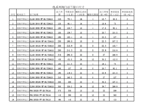
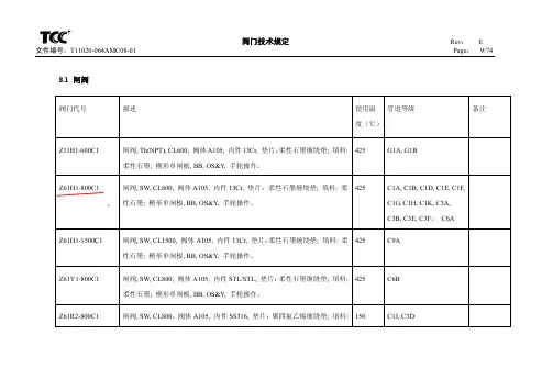
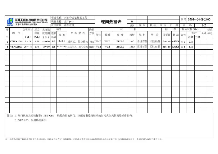
阀门数据表和外形图
- 格式:pdf
- 大小:243.72 KB
- 文档页数:15
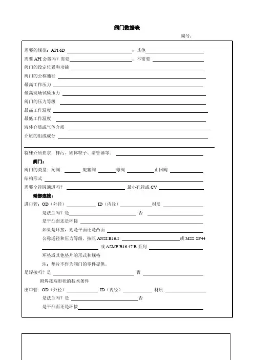
阀门数据表
编号:
如果是环接,则是平面还是凸面
公称通径和压力等级,按照ANSI B16.5 或MSS-SP44
或ASME B16.47 B系列
环垫或其他垫片的形式和规格
注:垫片不作为阀门的零件提供。
是焊接吗?是否
附焊接端形状的技术条件
长度:对结构长度的特殊要求?
阀门的操作:
需要附加操作机构吗?如果需要,则说明下面中的一个尺寸:
对于水平轴的手轮,阀门通道中心线到手轮中心线的距离:英寸
或者,对于垂直轴的手轮,阀门通道中心线到手轮轮缘中心间的距离:英寸。
注:有活动的扳手的旋塞阀,必须单独订购扳手。
需要扳手吗?
需要锁紧装置吗?型式
阀门的支承
需要支承筋或支承腿吗?
其他要求:
补充试验
耐火试验结构是否
NACE MR01-75 是否
泄压:如果需泄压装置,那么你对这些装置有特殊要求吗?
排放连接;有何要求?
旁通连接;有何要求
要求提供的文件
第三方证明或程序/试验:
需要涂漆或上涂层吗?
填表人:填表日期:
Rev:01。
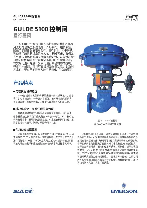
GULDE 5100控制阀直行程阀产品样本2023年9月GULDE 5100系列直行程控制阀和执行机构采用先进的紧凑型系统设计,外形精巧,结构紧凑,降低了零部件数量和复杂性,简单易用,便于维护。
整套阀门和执行机构符合ASME 标准要求,确保其在各种应用场合都具有优异的稳定性、可靠性和耐用性。
配合GULDE 3800SA 智能阀门定位器使用,可实现无连杆连接,对阀门进行精确可靠的控制,整体坚固耐用,并具有故障诊断报警功能。
此系列产品可广泛应用于控制各种工艺液体、气体和蒸汽。
5100控制阀和执行机构系统采用一体化模块设计,便于客户的应用和选型。
一旦选定了阀体、阀座尺寸和气源压力,便可确定执行机构的规格,不需进行复杂的执行机构选型。
整套控制阀和执行机构系统采用模块化设计,设计优良,在各种规格之间实现了最大程度的零部件共用。
5100执行机构共有总计十二种不同的弹簧组合,以适应各种阀门口径,进而实现多种气源压力选项,更切合用户工况。
使用动态加载填料。
标准配置的5100控制阀系统配有动态加载的PTFE V 型环填料。
动态加载设计有助于对工艺介质进行可靠密封,从而节约用户宝贵的工艺流体,减少排放。
耐用、可靠的动态加载填料系统还能减少维护成本和过程停机时间。
产品特点无需执行机构选型模块化设计,多种气源压力选项使用动态加载填料图1 – 5100控制阀配3800SA智能阀门定位器GULDE 5100控制阀G5100B0CN5100控制阀是单座阀,流体流向为向上流动(抗汽蚀内件为向下流动),采用阀杆导向型阀内件,阀座导向型阀内件或阀笼导向型阀内件。
每种阀门口径均提供非平衡式阀芯结构,非平衡式阀芯结构提供了更好的关闭性能和更大的流通能力;对于金属密封形式,阀内件使用不锈钢材料制成,对于各类腐蚀磨损工况,还提供了增加Stellite 合金硬化层的阀内件备选项;PTFE V 型环阀杆填料是5100控制阀的标准填料,动态加载填料系统提供出色的阀杆密封,且使用寿命更长;全尺寸阀内件和限流阀内件都具有等百分比和线性两种流量特性,用户可以根据自己的工况来任意选择。

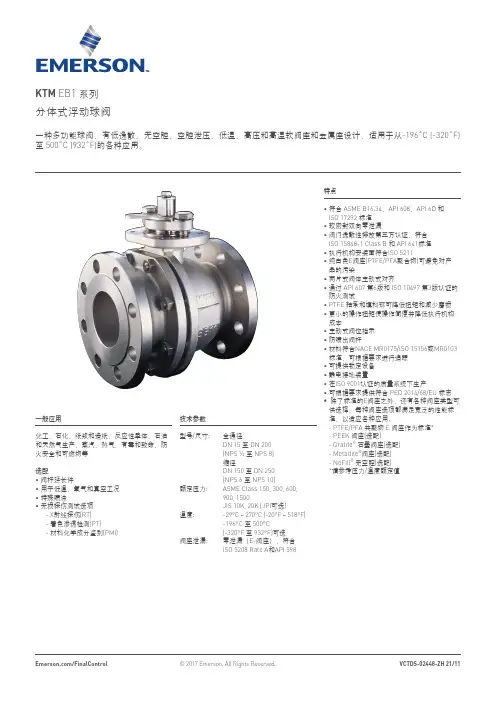
KTM EB1 系列分体式浮动球阀一种多功能球阀,有低逸散、无空腔、空腔泄压、低温、高压和高温软阀座和金属座设计,适用于从-196˚C (-320˚F) 至 500˚C (932˚F)的各种应用。
特点• 符合 ASME B16.34、API 608、API 6D 和 ISO 17292 标准• 软密封双向零泄漏• 阀门逸散性排放第三方认证,符合ISO 15848-1 Class B 和 API 641标准• 执行机构安装面符合ISO 5211• 纯白色E 阀座(PTFE/PFA 聚合物)可避免对产品的污染• 两片式阀体主动式对齐• 通过 API 607 第6版和 ISO 10497 第3版认证的防火测试• PTFE 轴承和填料环可降低扭矩和减少磨损• 更小的操作扭矩使操作简便并降低执行机构成本• 主动式阀位指示• 防喷出阀杆• 材料符合NACE MR0175/ISO 15156或MR0103标准,可根据要求进行追踪• 可提供锁定设备• 静电接地装置• 在ISO 9001认证的质量系统下生产• 可根据要求提供符合 PED 2014/68/EU 标志• 除了标准的E 阀座之外,还有各种阀座类型可供选择。
每种阀座选项都满足宽泛的性能标准,以适应各种应用。
- PTFE/PFA 共聚物 E 阀座作为标准* - PEEK 阀座(选配)- Gratite ® 石墨阀座(选配) - Metaltite ®阀座(选配) - NoFill ® 无空腔(选配) *请参考压力/温度额定值一般应用化工、石化、纸浆和造纸、反应性单体、石油和天然气生产、蒸汽、热气、有毒和致命、防火安全和可燃物等选配• 阀杆延长件• 用于低温、氧气和真空工况• 特殊喷涂• 无损探伤测试选项 - X 射线探伤(RT) - 着色渗透检测(PT) - 材料化学成分鉴别(PMI)技术参数型号/尺寸: 全通径DN 15 至 DN 200 (NPS ½ 至 NPS 8)缩径 DN 150 至 DN 250(NPS 6 至 NPS 10)额定压力: ASME Class 150, 300, 600,900, 1500JIS 10K, 20K (JPI 可选)温度: -29°C ~ 270°C (-20°F ~ 518°F) -196°C 至 500°C(-320°F 至 932°F)可选阀座泄漏: 零泄漏(E-阀座),符合ISO 5208 Rate A 和API 598设计特征ISO 5211标准执行机构安装法兰:符合 ISO 标准的顶法兰可以精确安装执行机构;执行机构连接螺栓与填料压盖螺栓是相对独立的;准确的对中可以减小阀门开关扭矩及内件磨损。
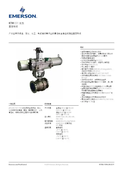
KTM E01 系列固定球阀特点•适用于高频工况的优化设计•在线可调式阀杆填料,无需拆卸阀门或执行器进行逸散性泄漏维护(API 608要求)•可提供防静电结构• 执行机构安装面符合ISO 5211• 双向切断的DBB结构,阀腔可以自卸压• 设计符合ASME B16.34• 可以满足PED要求• 面对面尺寸按照ASME B16.10 long pattern,法兰设计按照ASME B16.5• 通过耐火试验测试 API 607 / ISO 10497• 阀杆逸散泄漏测试满足 ISO 15848-1 ClassBH CO3•阀杆防出吹设计,并带有阀位指示• 软阀座采用金属支撑的RPTFE轴承,减小操作扭矩• 标准材质的RPTFE阀座满足API 598零泄漏• 金属阀座标准泄漏等级为FCI 70-2 Class V,可按要求提供更高的泄漏等级• 耐磨和高温工况可提供PEEK和Metaltite®的阀座•深冷和高温工况可提供延长杆设计• 零件材质可以满足NACE MR0175 / ISO 15156• 阀门符合SIL 3认证广泛应用于炼油、石化、化工、制浆造纸等行业的高性能全通径和缩径固定球阀一般应用API 608 / ISO 17292的应用包含在炼油、石化、化工领域中的高温、高压、高频等工况 ,以及高性能、特殊材质和工程设计结构等方案。
技术数据尺寸范围: 全通径 DN 40 至 DN 600(NPS 1½ 至 NPS 24)缩径 DN 80 至 DN 500(NPS 3 至 NPS 20)压力磅级: ASME Class 150, 300, 600,900, 1500面对面距离: ASME B16.10 Long Pattern 法兰标准: ASME B16.5 凸面法兰,RTJ 可选温度范围: 普通结构:-29 °C 至 150 °C(-20 °F 至 303 °F)特殊结构:-196 °C至 500 °C(-320 °F 至 932 °F)固定球的扭矩更小传统的浮动球设计,上游管道压力作用在关闭状态的球上,推动球往下游阀座上移动。
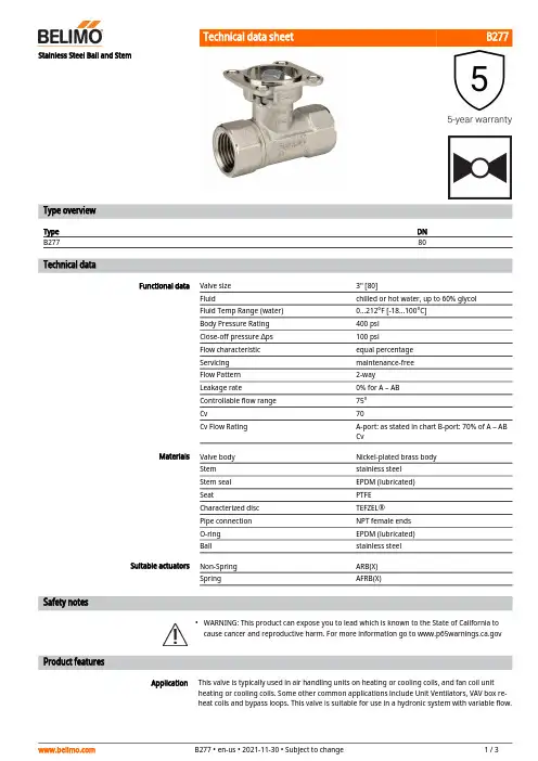
B277•ApplicationStainless Steel Ball and StemType overviewType DN B27780Technical dataFunctional dataValve size 3" [80]Fluidchilled or hot water, up to 60% glycol Fluid Temp Range (water)0...212°F [-18...100°C]Body Pressure Rating 400 psi Close-off pressure ∆ps 100 psiFlow characteristic equal percentage Servicing maintenance-free Flow Pattern 2-way Leakage rate0% for A – AB Controllable flow range 75°Cv70Cv Flow RatingA-port: as stated in chart B-port: 70% of A – AB CvMaterialsValve body Nickel-plated brass body Stem stainless steel Stem seal EPDM (lubricated)SeatPTFE Characterized disc TEFZEL®Pipe connection NPT female ends O-ring EPDM (lubricated)Ballstainless steel Suitable actuators Non-Spring ARB(X)SpringAFRB(X)Safety notesWARNING: This product can expose you to lead which is known to the State of California to cause cancer and reproductive harm. For more information go to Product featuresThis valve is typically used in air handling units on heating or cooling coils, and fan coil unit heating or cooling coils. Some other common applications include Unit Ventilators, VAV box re-heat coils and bypass loops. This valve is suitable for use in a hydronic system with variable flow.B277 Flow/Mounting detailsTwo-way valves should be installed with thedisc upstream.DimensionsType DNB27780ARB, ARXA B C D E F H110.1" [257] 5.8" [148]8.5" [217] 6.0" [152] 2.8" [71] 2.8" [71] 2.1" [53]ARQB, ARQXA B C D E F H1H29.9" [251] 4.2" [107]8.6" [219] 6.1" [155] 2.3" [58] 2.3" [58]0.8" [20]0.6" [15]AFRB N4, AFRX N4A B C D E F13.0" [330] 5.8" [148]10.3" [262]9.3" [235] 3.4" [86] 3.4" [86]B277ARB N4, ARX N4, NRB N4, NRX N4A B D E F11.4" [289] 5.8" [148]8.0" [203] 3.1" [80] 3.1" [80]AFRB, AFRXA B C D E F11.8" [299] 5.8" [148]9.1" [231] 6.6" [168] 2.0" [51] 2.0" [51]NEMA 4, Modulating, Spring Return, DirectCoupled, 24 V, Multi-Function Technology®Technical dataElectrical data Nominal voltage AC/DC 24 VNominal voltage frequency50/60 HzPower consumption in operation7.5 WPower consumption in rest position 3 WTransformer sizing10 VA (class 2 power source)Electrical Connection18 GA appliance cable, 3 ft [1 m], with 1/2"conduit connectorOverload Protection electronic throughout 0...95° rotationFunctional data Operating range Y 2...10 VOperating range Y note 4...20 mA w/ ZG-R01 (500 Ω, 1/4 W resistor)Input Impedance100 kΩ for 2...10 V (0.1 mA), 500 Ω for 4 (20)mA, 1500 Ω for PWM, On/Off and Floating pointOperating range Y variable Start point 0.5...30 VEnd point 2.5...32 VOptions positioning signal variable (VDC, PWM, on/off, floating point)Position feedback U 2...10 VPosition feedback U note Max. 0.5 mAPosition feedback U variable VDC variableDirection of motion motor selectable with switchDirection of motion fail-safe reversible with cw/ccw mountingManual override 5 mm hex crank (3/16" Allen), suppliedAngle of rotation90°Running Time (Motor)150 s / 90°Running time motor variable70...220 sRunning time fail-safe<20 sAngle of rotation adaptation off (default)Override control MIN (minimum position) = 0%MID (intermediate position) = 50%MAX (maximum position) = 100%Noise level, motor45 dB(A)Noise level, fail-safe62 dB(A)Position indication MechanicalSafety data Degree of protection IEC/EN IP66Degree of protection NEMA/UL NEMA 4XEnclosure UL Enclosure Type 4XAgency Listing cULus acc. to UL60730-1A/-2-14, CAN/CSAE60730-1:02, CE acc. to 2014/30/EU and2014/35/EUQuality Standard ISO 9001Ambient temperature-22...122°F [-30...50°C]FootnotesSafety dataAmbient temperature note -40...50°C for actuator with integrated heatingStorage temperature -40...176°F [-40...80°C]Ambient humidity Max. 100% RH Servicingmaintenance-freeMaterialsHousing material Die cast aluminium and plastic casing†Rated Impulse Voltage 800V, Type of Action 1, Control Pollution Degree 2.AccessoriesGatewaysDescriptionType Gateway MP to BACnet MS/TP UK24BAC Gateway MP to Modbus RTU UK24MOD Gateway MP to LonWorksUK24LON Electrical accessoriesDescriptionType Service Tool, with ZIP-USB function, for programmable andcommunicative Belimo actuators, VAV controller and HVAC performance devicesZTH USService toolsDescriptionTypeConnection cable 10 ft [3 m], A: RJ11 6/4 ZTH EU, B: 3-pin Weidmüller and supply connectionZK4-GEN Service Tool, with ZIP-USB function, for programmable and communicative Belimo actuators, VAV controller and HVAC performance devicesZTH USElectrical installationINSTALLATION NOTESActuators with appliance cables are numbered.Provide overload protection and disconnect as required.Actuators may also be powered by DC 24 V.Only connect common to negative (-) leg of control circuits.A 500 Ω resistor (ZG-R01) converts the 4...20 mA control signal to 2...10 V.Control signal may be pulsed from either the Hot (Source) or Common (Sink) 24 V line.For triac sink the Common connection from the actuator must be connected to the Hotconnection of the controller. Position feedback cannot be used with a triac sink controller; theactuator internal common reference is not compatible.IN4004 or IN4007 diode. (IN4007 supplied, Belimo part number 40155).Actuators may be controlled in parallel. Current draw and input impedance must be observed.Master-Slave wiring required for piggy-back applications. Feedback from Master to controlinput(s) of Slave(s).Meets cULus requirements without the need of an electrical ground connection.Warning! Live electrical components!During installation, testing, servicing and troubleshooting of this product, it may be necessary to work with live electrical components. Have a qualified licensed electrician or other individual who has been properly trained in handling live electrical components perform these tasks. Failure to follow all electrical safety precautions when exposed to live electrical components could result in death or serious injury.Wiring diagramsOn/Off Floating PointVDC/mA Control PWM ControlOverride Control Master - SlaveDimensions。
KEYSTONE OPTISEAL弹性阀座蝶阀应用于通用行业的对夹式和支耳式弹性阀座蝶阀特点• 顶部轴套吸收执行机构侧推力负载• 执行机构法兰符合ISO 5211标准• 可应用于高固体含量、有光泽的、无硅的涂料系统,确保优异的耐腐蚀性• 延长型阀体颈部,可直接满足管道绝缘保温的安装• 阀体定位孔便于在管道法兰之间安装和居中• 圆弧状抛光阀板边缘,实现完全的同心密封,降低扭矩,延长阀座寿命,达到气泡级密封关闭• 阀座可现场更换,阀座将阀体及阀杆与流体介质完全隔离• 主阀杆密封超过阀门的压力额定值,防止流体介质通过阀杆区泄漏到大气中• 副阀杆密封提供备用安全功能• 阀门安装在管道中无需法兰垫片• 高C v 值• 顶部和底部阀杆轴承,最优化了阀杆的支撑并最小化了阀杆摩擦(配置尺寸最大到DN 300),装配于除铸铁阀体之外的所有阀体材料• 对夹式和支耳式阀体设计,符合EN 593、ISO 5752/5 短结构标准• 所有阀门符合压力设备指令PED(97/23/EU)模块H - 带有CE 标志• 阀门可提供:KIWA, DNV, CU-TR 等证书一般应用食品和饮料加工,干固体块料输送、造纸厂、淤浆处理等,可提供无润滑脂或无硅油的阀门,用于涂料或氧气系统等特殊用途。
带有内衬PTFE 的阀座和PTFE 包覆的一体式阀板阀杆的OptiSeal ,非常适合需要卓越的耐化学性和无毒特性的应用场合。
技术数据压力(bar): 16 (铸铁阀体: 10 bar)管线末端压力(bar): 6-10-16温度(°C): -40至+160尺寸(DN): 40至300对夹式连接方式的法兰钻孔标准:DN 40-300: P N 10/16, ASME/ASTM B16.5Cl#150, JIS 10K, BS 表E 支耳式连接方式的法兰钻孔标准: PN 10/16 ASME/ASTM B16.5 Cl#150A SME/ASTM B16.47 Cl#150 系列AJIS 5K/10K弹性阀座蝶阀注1. 在订货时,必须详细说明阀门的法兰钻孔标准。
第共气源线为304或316不锈钢,气源线为304或316不锈钢,气源线为304或316不锈钢,带回讯、过滤减压阀等附件带回讯、过滤减压阀等附件带回讯、过滤减压阀等附件电磁阀电气线接入限位开关内电磁阀电气线接入限位开关内电磁阀电气线接入限位开关内备注 REMARKS开启关闭时间 OPEN/CLOSE TIME G1/4"G1/4"G1/4"其他 OTHER快排阀保位阀气控阀APL-210防护/防爆等级 Ex. CERTIFICATION IP67IP67IP67气源接头尺寸 AIR CONN. SIZE阀位开关阀位开关型号 POSITION SWITCH MODE APL-210APL-210电气接口尺寸 ELEC. CONN. SIZENPT1/2"NPT1/2"NPT1/2"电磁阀电磁阀型号 SOLENOID MODEL SCG531C001MS SCG531C001MS SCG531C001MS 电磁阀 型式SOLENOID TYPE 二位五通单电控电气接口尺寸 ELEC. CONN. SIZE ASCO厂家标准ASCO厂家标准ASCO厂家标准防护/防爆等级 Ex. CERTIFICATIONIP65IP65IP65二位五通单电控二位五通单电控电源 POWER SUPPLY 24V.DC 24V.DC 24V.DC 附件过滤器减压阀 REGULATORRPY RPY RPY 气源故障时阀位置 AIR FAIL VALVE POSITIONFL FLFL法兰标准及等级 FLANGE STD.& RATING HG/T20592-2009 PN25HG/T20592-2009 PN16HG/T20592-2009 PN16手轮机构 HAND WHEEL///供气压力 AIR SUPPLY PRESS. Mpa 0.6MPA 0.6MPA 0.6MPA 执行机构型号 ACTUATOR MODE No.RP-125DA RP-145DA RP-125DA 执行机构执行机构型式 ACTUATOR TYPE 齿轮齿条执行机构齿轮齿条执行机构齿轮齿条执行机构泄漏等级 LEAKAGE CLASSANSI IV ANSI VI ANSI VI最大允许声音水平Max.Allow.Sound Level Dba 法兰尺寸及密封面 FLANGE SIZE & FACING DN50 RF DN150 RFDN125 RF型式 TYPE气动硬密封球阀气动软密封硬靠背蝶阀气动软密封硬靠背蝶阀连接形式 CONNECTION TYPE法兰连接对夹连接对夹连接行程 TRAVEL90°90°90°填料 PACKING 柔性石墨PTFE PTFE 阀座材质 SEAT MATERIAL 合金钢PTFE PTFE 阀芯材质 PLUG MATERIAL 304CF8CF8阀体材质 BODY MATERIAL WCB 球墨铸铁球墨铸铁公称通径 NOMINAL DIAMETER DN50DN150DN125阀规格 VALVE SPECIFICATION型号 MODEL RPD-500RPD-800RPD-800正常流量 NOR.FLOW数量 QUANTITY 4210最大差压 MAX.DIFF.PRESSURE 操作压力 OPER.PRESSURE MPa(G)操作温度 OPER.TEMPER.℃280100100操作条件 OPERATING CONDITIONS工艺介质 PROCESS FLUID 蒸汽水水管道规格 LINE SPECIFICATIONDN50DN150DN125管道材质 LINE MATERIAL 用途 SERVICE位号 TAG NO.版次version number PNEUMATIC SHUTOFF VALVE2012.12.17-W仪表数据表业主(USER)INSTRUMENT DATA SHEET项目名称PROJECT 气动切断阀设计单位DES.UNIT。
12MPa 3°C 4t/h 5MPa 6°C 78cm2910cm211mm 12mm 1314MPa 4015MPa 4116°C 4217°C 431844bar 47194520462147224823492450255126522753285429553056315732583359346035613662373837Valve Data SheetCCISulzer ValvesProject Xibaipo, 2 x 600 MW Valve Type HBSE 160-250Customer China Power Complete Equipmen Function HP Steam Control Tender No.040323-095005-5Quantity / unit 2 (1 per unit)Order No.Tag No.Operating Conditions Case 1Case 2Case 3Case 4Case 5Case 6Case 7Condition Design Cold Warm Hot Super Hot ..Valve Inlet Temperature 538.00470.00Valve Inlet Pressure 24.20470.00527.00 Valve Inlet Flow 585292.5292.5292.5292.5 Valve Outlet Pressure 4.656 1.15 1.15 1.15 1.15 Valve Outlet Temperature 297.40220.00220.00230.00240.00 Required Kv 285.79469.22433.05406.75411.67 Required Flow area 74.86122.91113.44106.55107.84 Actual Valve Kv 636.75636.75636.75636.75636.75 Actual Valve Flow area 166.80166.80166.80166.80166.80 Maximum Valve Stroke 105105105105105 Required Valve Stroke35.1057.9552.6849.3049.93 ValveActuator Design Pressure Inlet 26.8Type Pneumatic Design Temp. Inlet 548Hydr Fluid Pressure Design Pressure Outlet 5.5Model / Size CCI-STI Design Temp. Outlet 350Control Element Test Pressure 1.5 * Design pressure Air Pressure Min. / Max.Body Material A-182 F91Stroking time modulating < 10 sec.Inlet Pipe dimension DN 350Positioner Type Standard Pipe Material A355 P91Model CCI-STI Nozzle Material A-182 F91Input signal 4 - 20 mA Connection Butt weld Increasing ignal Opens Valve Outlet Feedback Transmitter Yes, incl. Limit switches Pipe dimension DN 600Pipe Material A672B70CL32Safety device Type Nozzle Material A-182 F22Function open/close Connection Butt weld Quantity vertical Stroking time Stem Orientation Linear Function open/close top Quick stroking dev. Type ANSI/FCI Class V Stroking time Flow To Close Quantity Dimensional Drawing Remarks:Separate AccumulatorSectional Drawing Quality Std CCI-QA2000Revisions 1. IssueDate:23-Mar-04Name: A. Sieber Rev.1Date:Name:Line:Rev.2Date:Name:Line:Rev.3Date:Name:Line:Rev.4Date:Name:Line:Rev.5Date:Name:Line:7.508.108.608.92 470.00Actuator Orientation Valve Caracteristic Flow Direction Shutoff ClassC O N T R O L V A L V ED A T A S HE ETProject Xibaipo, 2 x 600 MW Tag #Buyer China Power Complete Equipment Co., Ltd. Item #Owner Qty. 2 (1 per unit)Inq. Rev.Date Model 100DSVProp. 040323-095005-5 Rev.Date D-SHT Rev. 0 Dwg # P.O. Application HP Spray Control1 Fluid Water/Steam Crit Press 3208.2 psi A Crit Temp 374.2 deg CUnits Design Cold Warm Hot Super Hot2 Mass Flow Rate mt/hr 105.8 59.97 58.91 54.4 68.673 Inlet Pressure (P1) MPa A 31.77 25.93 25.93 25.94 25.91 4 Outlet Pressure (P2) MPa A 5.81 1.81 1.81 1.77 1.895 Differential (∆P) MPa 25.96 24.12 24.12 24.17 24.02 6 Inlet Temp. (T1) deg C 192.4 141.0 141.0 141.0 141.0 7 Density kg/m3 893.7 938.5 938.5 938.5 938.58 Vapor Pressure MPa A 1.322 0.3718 0.3718 0.3718 0.37189 Viscosity cpoise 0.1472 0.2015 0.2015 0.2015 0.2015 10 Required Flow Cv 8.3 4.7 4.7 4.3 5.4 11 Travel 12 SPL dBA 75.0 75.0 75.0 75.0 75.0 13 Pipe In 133 x 14 mm 38Actuator Type Spring Diaphragm 14 Pipe Out 133x 14 mm 39 Mfr / Model CCI / 50015 Pipe Matl In Carbon Steel Out Carbon Steel 40 Failure Mode Fail Close16 Type Globe Size 2 X 2 inches 41 Supply Type Compressed Air 17 Design P In 35.0 Out 7.0 MPa A 42 Supply (Min) 0.3585 MPa G18 Design T In 250.0 Out 250.0 deg C 43 Supply (Max) 0.3585 MPa G19 Rating(s) In 2500 Special Out 2500 Std PN 420 44 Stem Orientation Vertical Up20 Material WCB/F22 45 Manual Override N/A21 Connect In Butt Weld 46 N/A22 Connect Out Butt Weld 47 Positioner Type Electro-Pneumatic 23 Flow Dir. Flow to Close (OTP) 48 Mfr / Model CCI/STI / Standard 24 Bonnet Type Bolted 49 Input Signal 4 to 20 mA25 Bonnet Seal Gasket 50 Increasing Signal Opens the Valve 26 Packing Type Chevron 51 Cam Characteristic Linear27 Packing Matl Teflon 5228 Trim Type Drag®, Multi-Path, Multi-Stage 53 Filter (Filter Reg) Standard29 Trim Size 1.5 inches Rated Cv 10.7 54 Limit/Torque Switch Open & Close 30 Trim Char. Characterized 55 Position Feedback Standard31 Number of Pressure Reducing Stages Min 14 Stages 56 I - P Transducer Integral w/Positioner 32 Plug Type Balanced 57 Solenoid Valve(s) N/A33 Stem Matl Inconel 718 58 Elect Housing STD Standard34 Plug Matl Inconel 718 59 Seat Leakage ASME/FCI Class V 35 Seat Matl 300 Series 60 Open Time(s) <10 sec36 Guide Matl Inconel 718 61 Close Time(s) <10 sec3762 Approx. Weight 200 kg N o t e s / S p e c i a l I n s t r u c t i o ns63 To eliminate uncontrolled pressure letdown problems, a number of discrete pressure reduction stages are provided. 64 The liquid velocity exiting the trim will not exceed 100 ft/sec (30 m/sec).65 To prevent line trash damage to seating surfaces, the flow direction will be flow to close.66 For easy maintenance, the trim is a quick change type. No components are screwed or welded to the body or bonnet. 67 Valve design to ASME B16.34, latest edition.68 Control valve sizing is based on ISA S75.01, 'Flow Equations For Sizing Control Valves'.6970 2 transition pieces 2" / 5" per v alve will be supplied loose.7172737475Date :3/23/2004Customer :China Power Complete Equipment Co., Ltd.Project :Xibaipo, 2 x 600 MWInq. No.2004-3Reference No.040323-095005-5.W1Tag No.HP Spray IsolationNo. of valves 2 (1 per unit)Operating data Design Cold Warm Design Water InletQ1[kg/h]105800.059970.058910.0p[kp/cm² a]320.00260.00260.00350.00 t[°C]192.4141.0141.0250.0 h[kcal/kg]198.9145.7145.7v[m³/kg]0.001120.001070.00107K[-]0.0000.0000.000Water OutletQ2[kg/h]105800.059970.058910.0p[kp/cm² a]317.77259.31259.34350.00 t[°C]192.4141.0141.0250.0 h[kcal/kg]198.9145.7145.7v[m³/kg]0.001120.001070.00107Calculated data Design Cold WarmWater ValveKv calc[-]74.974.574.9Inlet pipe[DN]125Diam. ID/OD[mm]-/-Inlet Velocity[m/s] 2.7 1.4 1.4Outlet pipe[DN]125Diam. ID/OD[mm]-/-Outlet Velocity[m/s] 2.7 1.4 1.4System design consideration CCI document "Installation Guidelines II500.0o/4en"Date :3/23/2004Customer :China Power Complete Equipment Co., Ltd.Project :Xibaipo, 2 x 600 MWInq. No.2004-3Reference No.040323-095005-5.W1Tag No.HP Spray IsolationNo. of valves 2 (1 per unit)Operating data Hot Super Hot Design Water InletQ1[kg/h]54400.068670.0p[kp/cm² a]260.00260.00350.00 t[°C]141.0141.0250.0h[kcal/kg]145.7145.7v[m³/kg]0.001070.00107K[-]0.0000.000Water OutletQ2[kg/h]54400.068670.0p[kp/cm² a]259.43259.10350.00 t[°C]141.0141.0250.0h[kcal/kg]145.7145.7v[m³/kg]0.001070.00107Calculated data Hot Super HotWater ValveKv calc[-]74.474.7Inlet pipe[DN]125Diam. ID/OD[mm]-/-Inlet Velocity[m/s] 1.3 1.7Outlet pipe[DN]125Diam. ID/OD[mm]-/-Outlet Velocity[m/s] 1.3 1.7System design consideration CCI document "Installation Guidelines II500.0o/4en"Selected BTG Water pressure reducing equipment.Reference No.040323-095005-5.W1Page 3/3 Date :3/23/2004Tag No.HP Spray IsolationValve type VS - 40TValve design Single-seatedSeat40Leakage class VKvc[-]74.9Kvs[-]75Control plug type ContourCharacteristic Modified LinearCapacity factor[%]100Full Stroke[mm]32Actuating force[kN]53.5Shut-off-∆p[kp/cm² a]350.0ConnectionsInlet[DN]125 BWERating ASME B16.25, Fig. 2aOutlet[DN]125 BWERating ASME B16.25, Fig. 2aMaterialsInlet A-105Body A-105Outlet A-105Stem X19CrMoVNbN111 (AISI 616)Plug X19CrMoVNbN111 (AISI 616)Seat Haynes 25Packings GraphiteDesign code ASME VIIIActuator Type STI SC/V 390-100Model Pneumatic PistonStroke / MaxForce[mm/kN]100 / 57.0Positioner NoneAir supply conn. / Stroke time1/2" / 2.0 sPower supply 5.0 kp/cm²(g)Input signal On/OffIncreasing signal Valve opensPower supply failure Valve closesAccessories 1 Air bottle1 Trip valve1 Limit switch opened1 Limit switch closedE12MPa 3°C 4t/h 5MPa 6°C 7891011mm 12mm 1314MPa 4015MPa 4116°C 4217°C 431844bar 47194520462147224823492450255126522753285429553056315732583359346035613662373839Valve Data SheetCCISulzer ValvesProject Xibaipo, 2 x 600 MW Valve Type NBSE 55-500-1Customer China Power Complete Equipmen Function LP Steam Control Tender No.040323-095005-5Quantity / unit 4 (2 per unit)Order No.Tag No.Operating Conditions Case 1Case 2Case 3Case 4Case 5Case 6Case 7Condition Design Cold Warm Hot Super Hot ..Valve Inlet Temperature 566.00320.00Valve Inlet Pressure 4.20 1.10 1.10320.00435.00530.00 Valve Inlet Flow 345.4176.235175.705173.45180.585 Valve Outlet Pressure 0.80.60.60.60.6 Valve Outlet Temperature 171.00171.00171.00171.00171.00 Required Kv 1080.451757.171751.881907.222125.77 Required Cv 1250.622033.922027.812207.602460.58 Actual Valve Kv 2386.002386.002386.002386.002386.00 Actual Valve Cv 2762.002762.002762.002762.002762.00 Maximum Valve Stroke 200200200200200 Required Valve Stroke67.22115.51115.02130.62161.41 ValveActuator Design Pressure Inlet 5.3Type Pneumatic Design Temp. Inlet 573Hydr Fluid Pressure Design Pressure Outlet 1.6Model / Size CCI-STI Design Temp. Outlet 250Control Element Test Pressure 1.5 * Design pressure Air Pressure Min. / Max.Body Material WC9Stroking time < 10 sec.Inlet Pipe dimension DN 600Positioner Type Standard Pipe Material A335P91Model CCI-STI Nozzle Material A-182 F91Input signal 4 - 20 mA Connection Butt weld Increasing ignal Opens Valve Outlet Feedback Transmitter Yas, incl. Limit switches Pipe dimension DN 750Pipe Material 10 CrMo910Safety device Type Yes Nozzle Material WC9Function open/close close (condeser protection)Connection Butt weld Quantity 1Stroking time < 3Stem Orientation Function open/close Quick stroking dev. Type Stroking time Shutoff Class Quantity Flow Direction ANSI/FCI Class V Flow To Close Remarks:Separate AccumulatorCCI-QA2000Revisions 1. IssueDate:23-Mar-04Name: A. Sieber Rev.1Date:Name:Line:Rev.2Date:Name:Line:Line:Rev.3Date:Name:Rev.4Date:Name:Rev.5Date:Name:Line:1.10 1.10 Line:Quality Std Sectional Drawing Dimensional Drawing Linear vertical top Actuator Orientation Valve Caracteristic12MPa 3°C 4t/h 5MPa 678cm29mm 1011MPa 4012°C 41134214431544bar 471645174618471948204921502251235224532554265527562857295830593160326132623232CCISulzer ValvesProject Xibaipo, 2 x 600 MW Valve Type 840 H 2"Customer China Power Complete Equipmen Function LP Spraywater Control Tender No.040323-095005-5Quantity / unit 4 (2 per unit)Order No.Tag No.Operating Conditions Case 1Case 2Case 3Case 4Case 5Case 6Case 7Condition Design Cold Warm Hot Super Hot ..Valve Inlet Pressure 2.88 3.41 3.41 3.37 3.30 Valve Inlet Temperature 49.1049.1049.1049.1049.10 Valve Inlet Flow 111.2920.9820.9237.1853.12 Valve Outlet Pressure 1.310.930.930.960.99 Required Kv 28.25 4.24 4.227.6211.10 Actual Valve Kv 34.5634.5634.5634.5634.56 Actual Valve Flow area Maximum Valve StrokeValveActuator Design Pressure Inlet 4Type Pneumatic diaphragm Hydr Fluid Pressure Model / Size MSD II Air Pressure Min. / Max.Control Element Pipe dimension DN 80Stroking time modulating < 10 sec.Pipe Material Nozzle Material WCB Positioner Type Standard Connection Butt weld Model Outlet Input signal 4 - 20 mA Pipe dimension DN 80Increasing ignal Opens Valve Pipe Material Feedback Transmitter Yes, incl. Limit switches Nozzle Material WCB Connection Butt weld Safety device Type Function open/close Stem orientation Quantity Actuator orientation Stroking time Trim Type Valve Characteristic Equal percentage Quick stroking dev. Type Flow Direction Flow to Close Function open/close Shutoff Class ANSI / FCI Class V Quantity Dimensional Drawing Stroking time Sectional Drawing Remarks Separate AccumulatorQuality Std CCI-QA2000Revisions 1. IssueDate:23-Mar-04Name: A. Sieber Line:Rev.1Date:Name:Rev.2Date:Name:Rev.3Date:Name:Name:Line:Body Material WCB Inlet Rev.5Date:Name:Rev.4Date:Design Temp. Inlet 150Test Pressure 1.5 * Design pressure Line:Line:Line:12MPa 3°C 4t/h 5MPa 678cm29mm 1011MPa 4012°C 41134214431544bar 4716451746184719482049215022512352245325542655275628572958305931603261336234CCISulzer ValvesProject Xibaipo, 2 x 600 MW Valve Type 840 G 2" Customer China Power Complete Equipmen Function LP Spraywater Isolation Tender No.040323-095005-5Quantity / unit 4 (2 per unit)Order No.Tag No.Operating Conditions Case 1Case 2Case 3Case 4Case 5Case 6Case 7Valve Inlet Pressure 3.43 3.43Condition Design 3.43 3.43 3.43 Valve Inlet Temperature 49.149.149.149.149.1 Valve Inlet Flow 111.2920.9820.9237.1853.12 Valve Outlet Pressure 2.88 3.41 3.41 3.37 3.30 Required Kv 47.5247.5247.5247.5247.52 Actual Valve Kv 47.5247.5247.5247.5247.52 Actual Valve Flow area Maximum Valve Stroke4040404040 ValveActuator Design Pressure Inlet 4Type Pneumatic diaphragm Test Pressure 1.5 * Design pressure Hydr Fluid Pressure Design Temp. Inlet 150Model / Size MSD II Body Material WCB Control Element Inlet Air Pressure Min. / Max.Pipe dimension DN 80Stroking time < 10 sec.Pipe Material Nozzle Material WCB Positioner Type On / off control Connection Butt weld Model Outlet Input signal op/cl Pipe dimension DN 80Increasing ignal Pipe Material Feedback Transmitter Limit switches Nozzle Material WCB Connection Butt weld Safety device Type Function open/close Stem orientation vertical Quantity Actuator orientation top Stroking time Trim Type Flow Direction Flow to Close Quick stroking dev. Type Shutoff Class ANSI / FCI Class V Function open/close Dimensional Drawing Quantity Sectional Drawing Stroking time Quality Std Remarks:CCI-QA2000Separate AccumulatorRevisions 1. IssueDate:23-Mar-04Name:A, Sieber Line:Rev.2Date:Name:Line:Rev.1Date:Name:Date:Name:Line:Rev.4Date:Name:Line:Rev.3Rev.5Date:Name:Line:Cold Warm Hot Super Hot ..。