多功能光电计时器操作说明简表与使用说明书
- 格式:doc
- 大小:984.00 KB
- 文档页数:8

CX-T02型、CX-T03型可编程多功能电子定时器使用说明书一、产品简介:CX-T02型、CX-T03型可编程多功能电子定时器,是一个以微电脑处理器为核心配合电子电路等组成的电源开关控制装置。
它可预设定每天或一周内20次不同时间的开/关控制,还具有倒计时、任意循环定时、键盘锁定功能和12/24小时制转换功能。
本机内置一枚可充电镍氢电池作为备用电源,在脱离市电电源的情况下,仍可保持计时显示和储存的各项数据达9个月以上。
它采用便携式移动插头形式和微功耗待机电路,可以控制电热水器、电饭煲、饮水机、电动自行车限时充电控制、灯具等各种电器。
您使用本产品后,各种电器将根据您的要求实现自动开启和关闭,既省电又方便,是真正的节电产品。
二、技术参数:执行标准:GB/T14536.1-1998 GB/T14536.8-1996额定电压:220V ~50Hz额定电流:CX-T02型10A(阻性)CX-T03型16A(阻性)工作温度:-20~70℃计时误差:≤±1秒/天三、系统功能介绍:1.液晶全屏字符,如右图所示:2. 本机在时钟状态下,按“模式”键可将工作状态设定为所需的方式。
设定顺序为:关自动开循环 Z Z(倒计时)关电源输出处于经常关闭状态。
自动电源输出处于执行编写的定时开/关程序状态。
开电源输出处于经常开启状态。
循环电源输出按照您设定的开启时间长度和间隔时间长度(关闭时长)来循环工作。
Z Z电源输出处于倒计时(延时关机)状态,最长时间为 23小时59分,最短为1分钟。
C 按此键后系统将清除所有储存的数据,系统恢复到初始状态。
四、操作方法在本机进入时钟状态后,可按以下方法进行操作:(一)、校正星期和时间:按“模式”键将定时器工作状态设定为“关”,在此状态下左手按住“时钟”键不放,右手按“日期”键,将星期调整为当前日期,调整好日期(星期)后再按“时”和“分”键将时钟调整为当前的标准时间。
(二)、设定倒计时(延时关机)时间:按“模式”键将工作状态切换至Z Z状态,电源输出即处于开启状态(初始默认时间为8小时),屏幕显示如右图所示:在此状态下,按“时”或“分”键修改您所需要本机开启通电的时间,每按一次“时”或“分”键,时间将减少1小时或1分钟,最大设定时间为23小时59分。
..' 多功能电力监测仪使用手册版本:3.0杭州正普科技有限公司使用前必读在您使用本产品之前,请务必仔细阅读此使用手册内容,正确按照用户手册指导操作,这会有助于您更好地使用本产品,并有助于解决现场出现的各种问题。
1、监测仪在施加工作电源之前,务必确保工作电源在仪表规定范围之内;2、现场安装使用时,电流输入端子严禁开路,电压输入端子严禁短路;3、通讯端子(RS485)严禁施加高压;4、使用时仪表接线方式务必与内部系统设置方式一致;5、与后台通讯时,仪表通讯参数务必与后台一致;不能带电拔插通信接口;6、本手册中的信息如有变动,恕不另行通知;我公司自始至终本着“质量第一服务第一”的宗旨,将以优质的产品、优良的服务奉献给国内外用户!●使用前请仔细阅读本用户使用手册●请注意妥善保存目录一、概述-------------------------------------------------- 1二、型号定义---------------------------------------------- 1三、尺寸对照表-------------------------------------------- 1四、型号与功能对照表-------------------------------------- 2五、技术指标---------------------------------------------- 3六、外形及安装尺寸---------------------------------------- 4七、接线图------------------------------------------------ 6八、操作说明---------------------------- 7(RS485通讯规约、CT/PT设置、开关量操作、变送输出操作)..'一、概述多功能电力监测仪具有对电网中电流、电压、频率、有功功率、无功功率、视在功率、电能、功率因数等进行同时测量的功能。

FeaturesRated control supply voltage 24‑48 V DC, 24‑240 V AC Multifunction timer with 10 timing functions:ON‑delay, OFF‑delay with auxiliary voltage, Impulse‑ON, Impulse‑OFF with auxiliary voltage, Symmetrical ON‑ and OFF‑delay, Flasher starting with ON or OFF , Pulse former, Accumulative ON‑delay, ON/OFF‑functionOne device includes 10 time ranges (0.05 s ‑ 300 h) 1 c/o contactControl input with voltage‑related triggering to start timing, to stop/pause timing or to select timing function2 LEDs for status indication Width of 22.5 mmSealable transparent cover (optional accessory) for protection against unauthorized changes of time valuesIntegrated marker labelApprovalsA UL 508, CAN/CSA C22.2 No.14C GL D GOSTK CB scheme ECCCMarksa CE bC‑TickOrder dataOrder data ‑ AccessoriesAdapter for screw mounting on panelSealable transparent coverMarker labelᕃᕆᕇᕄᕅᕈ2C D C 251 048 F 0t 07a Rotary switch for thepreselection of the time range b Potentiometer with directreading scale for the fine adjustment of the time delay c Rotary switch for thepreselection of the timing function d U/T: green LED ‑Vcontrol supply voltage applied W timing e R: yellow LED ‑Voutput relay energizedApplicationThe CT ‑S range timers are designed for use in industrial applications. They operate over a universal range of supply voltages and a large time delay range, within compact dimensions. The easy‑to‑set front‑face potentiometers, with direct reading scales, provide accurate time delay adjustment.Multifunction timers are ideally suited for service and maintenance applications, because one device can replace a number of time relays with different functions, voltage and time ranges. This reduces inventory and saves money.Operating modeThe CT ‑MVS.22 with 2 c/o contacts offers 11 timing functions. The function is rotary switch selectable on the front of the unit. Each function is indicated by an international function symbol.One of 10 time ranges, from 0.05 s ‑ 300 h, can be selected with an other rotary switch. The fine adjust‑ment of the time delay is made via an internal potentiometer, with a direct reading scale, on the front of the unit.Timing is displayed by a flashing green LED labelled U/T.Function diagramsRemarksLegend:G Control supply voltage not applied / Output contact open B Control supply voltage applied / Output contact closed A1‑Y1/B1 Control input with voltage‑related triggeringTerminal designations on the device and in the diagrams:The c/o contact is designated 15‑16/18. Control supply voltage is applied to terminals A1‑A2. Function of the yellow LED:The yellow LED R glows as soon as the output relay energizes and turns off when the output relay de‑energizes.A ON-delayThis function requires continuous control supply voltage for timing.Timing begins when control supply voltage is applied. The green LED flashes during timing. When the selected time delay is complete, the output relay energizes and the flashing green LED turns steady. If control supply voltage is interrupted, the output relay de‑energizes and the time delay is reset.A1-A215-1615-182C D C 252 011 F 0207green LEDt = adjusted time delayFunction diagramsA + Accumulative ON-delayThis function requires continuous control supply voltage for timing.Timing begins when control supply voltage is applied. The green LED flashes during timing. When the selected time delay is complete, the output relay energizes and the flashing green LED turns steady. Timing can be paused by closing control input A1-Y1/B1. The elapsed time t 1 is stored and continues from this time value when A1-Y1/B1 is re‑opened. This can be repeated as often as required. If control supply voltage is interrupted, the output relay de‑energizes and the time delay is reset.B OFF-delay with auxiliary voltageThis function requires continuous control supply voltage for timing.If control input A1-Y1/B1 is closed, the output relay energizes immediately. If control input A1-Y1/B1 is opened, the time delay starts. The green LED flashes during timing. When the selected time delay is complete, the output relay de‑energizes and the flashing green LED turns steady.If control input A1-Y1/B1 recloses before the time delay is complete, the time delay is reset and the out‑put relay does not change state. Timing starts again when control input A1-Y1/B1 re‑opens. If control supply voltage is interrupted, the output relay de‑energizes and the time delay is reset.AB Symmetrical ON- and OFF-delayThis function requires continuous control supply voltage for timing.Closing control input A1-Y1/B1 starts the ON‑delay t 1. When timing is complete, the output relay ener‑gizes. Opening control input A1-Y1/ B1 starts the OFF‑delay t 2. Both timing functions are displayed by the flashing green LED. When the OFF‑delay t 2 is complete, the output relay de‑energizes.If control input A1-Y1/B1 opens before the ON‑delay t 1 is complete, the time delay is reset and the out‑put relay remains de‑energized. If control input A1-Y1/B1 closes before the OFF‑delay t 2 is complete, the time delay is reset and the output relay remains energized.If control supply voltage is interrupted, the output relay de‑energizes and the time delay is reset.A1-A2 15-1615-18A1-Y1/B12C D C 252 016 F 0207green LEDt = adjusted time delayt 1 + t 2 = tt 3 = pause timingA1-A2 15-1615-18A1-Y1/B12C D C 252 014 F 0207green LEDt = adjusted time delayA1-A2 15-1615-18A1-Y1/B12C D C 252 018 F 0207green LEDt 1 = adjusted ON-delay t 2 = adjusted OFF-delay t 1 = t 2Function diagramsCA Impulse-ONThis function requires continuous control supply voltage for timing.The output relay energizes immediately when control supply voltage is applied and de‑energizes after the set pulse time is complete. The green LED flashes during timing. When the selected pulse time is com‑plete, the flashing green LED turns steady.If control supply voltage is interrupted, the output relay de‑energizes and the time delay is reset.CB Impulse-OFF with auxiliary voltageThis function requires continuous control supply voltage for timing.If control supply voltage is applied, opening control input A1-Y1/B1 energizes the output relay immedi‑ately and starts timing. The green LED flashes during timing. When the selected pulse time is complete, the output relay de‑energizes and the flashing green LED turns steady.Closing control input A1-Y1/B1, before the pulse time is complete, de‑energizes the output relay and resets the pulse time.If control supply voltage is interrupted, the output relay de‑energizes and the time delay is reset.DE Flasher, starting with ON or OFFApplying control supply voltage starts timing with symmetrical ON / OFF times. The cycle starts with an ON time first.Closing control input A1-Y1/B1, with control supply voltage applied, starts the cycle with an OFF time first. The ON / OFF times are displayed by the flashing green LED, which flashes twice as fast during the OFF time.If control supply voltage is interrupted, the output relay de‑energizes and the time delay is reset.H Pulse formerThis function requires continuous control supply voltage for timing.Closing control input A1-Y1/B1 energizes the output relay immediately and starts timing. Operating the control contact switch A1-Y1/B1 during the time delay has no effect. The green LED flashes during tim‑ing. When the selected ON time is complete, the output relay deenergizes and the flashing green LED turns steady. After the ON time is complete, it can be restarted by closing control input A1-Y1/B1. If control supply voltage is interrupted, the output relay de‑energizes and the time delay is reset.A1-A2 15-1615-182C D C 252 020 F 0207green LEDt = adjusted pulse timeA1-A2 15-1615-18A1-Y1/B12C D C 252 022 F 0207green LEDt = adjusted pulse timeA1-A2 A1-Y1/B115-1615-182C D C 252 024 F 0207green LEDt = adjusted flashing timeA1-A2 15-1615-18A1-Y1/B12C D C 252 026 F 0207green LEDt = adjusted pulse timeFunction diagramsG ON/OFF-functionThis function is used for test purposes during commissioning and troubleshooting.If the selected max. value of the time range is smaller than 300 h (front‑face potentiometer “Time sector” not 300 h), applying control supply voltage energizes the output relay immediately and the green LED glows. Interrupting control supply voltage, de‑energizes the output relay.If the selected max. value of the time range is 300 h (front‑face potentiometer “Time sector” = 300 h) and control supply voltage is applied, the green LED glows, but the output relay does not energize. Time settings and operating of the control inputs have no effect on the operation.Connection diagram15‑16/18c/o contactA1‑A2Rated control supply voltage U S 24‑48 V DC or 24‑240 V AC A1‑Y1/B1Control inputWiring instructionsControl input(voltage-related triggering)The control input Y1/B1 is triggered with electric potential against A2. It is possible to use the control supply voltage from terminal A1 or any other voltage within the rated control supply voltage range.A1-A215-1615-182C D C 252 028 F 0207green LEDTime sector ≠ 300 hTime sector = 300 hA1A1Y1/B115A2161815Y1/B11816A22C D C 252 004 F 0b 06L(+)N(-)2C D C 252 102 F 0b 06L(+)L(+)N(-)L(-)2C D C 252 103 F 0b 06Technical data= 25 °C and rated values, unless otherwise indicated Data at TaTechnical diagramsLoad limit curveA C v o l t a g e [V ]D C v o l t a g e [V ]2C D C 252 150 F 0206AC load (resistive)DC load (resistive)Derating factor Fcos ϕD e r a t i n g f a c t o r F2C D C 252 124 F 0206Contact lifetimeSwitching current [A]S w i t c h i n g c y c l e s2C D C 252 148 F 0206Dimensionsin mmCT-MVS.122C D C 252 188 F 0b 05Dimensions accessoriesin mmADP .01 - Adapter for screw mounting on panelCOV .01 - Sealable transparent coverMAR.01 - Marker label2C D C 252 185 F 00052C D C 252 186 F 00052C D C 252 008 F0010Further documentationYou can find the documentation on the internet at /lowvoltage R Control Products R Electronic Relays and ControlsSynonymsABB STOTZ-KONTAKT GmbHP. O. Box 10 16 8069006 Heidelberg, Germany Phone: +49 (0) 6221 7 01-0Fax: +49 (0) 6221 7 01-13 25E-mail:*****************.comYou can find the address of your local sales organisation on theABB home page/contacts-> Low Voltage Products and Systems Contact usNote:We reserve the right to make technical changes or modify the contents of this document without prior notice. With regard to purchase orders, the agreed particulars shall prevail. ABB AG does not accept any responsibility whatsoever for potential errors or possible lack of information in this document.We reserve all rights in this document and in the subject matter and illustrations contained therein. Any reproduction, disclosure to third parties or utilization of its contents – in whole or in parts – is forbidden without prior written consent of ABB AG. Copyright© 2010 ABBAll rights reserved D o c u m e n t n u m b e r 2 C D C 1 1 1 0 8 9 D 0 2 0 1 ( 0 5 / 1 0 )。

1.该计时器由争鸣口才网独家提供,该程序为VB制作,美工方面相当抱歉,请见谅!
2.请使用1024*768分辨率方可使该产品达到最佳显示效果,在使用前请先使用“计时演示”将声音和图象文件导入内存,以免正式使用时出错。
时间紧迫时也可不导入,不会有较大的影响。
3.请大家在使用时确保声音文件“1.wav”与计时程序同在一个文件夹中,以免影响计时提示音。
4.本程序由争鸣口才网提供;软件制作由西南科技大学经济管理学院管理0403班黄璜完成。
5.如有疑问请加QQ:521267657,E-Mail:huanghuang365@
6.本程序为免费产品,欢迎大家使用,谢谢您对我们的支持!
小广告:欢迎登陆干锅熊拍拍小店/11785082
注意:对于新加入的盘问或攻辩阶段计时,点击总计时的“开始”按钮后,“提问分计时”会自动开始,计时人员只需要在提问一方提问结束或提问时间到时按“回答计时”按钮即可。
在回答方时间到或回答完毕时,计时人员需按“分计时重置”按钮,恢复分计时系统的计算时间并且分计时器会自动开启提问计时,此时请主席提示提问方尽快作答。
全过程操作可以用键盘回车键进行控制。
如有疑问请加QQ521267657。
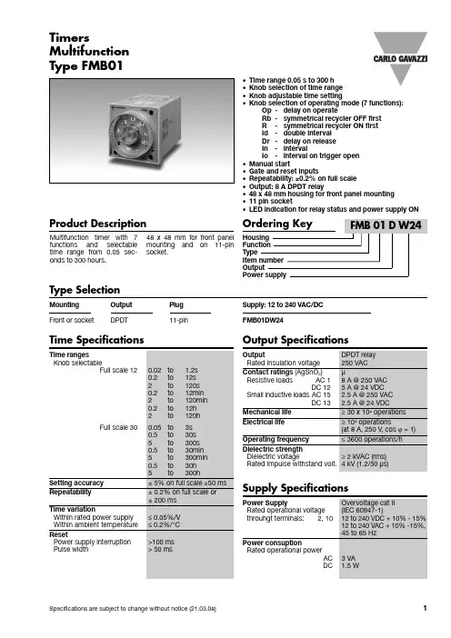
Product DescriptionMultifunction Multifunction timer with 7functions an d selectable time range from 0.05 sec-onds to 300 hours.48 x 48 mm for front panel mounting an d on 11-pin socket.•Time range 0.05 s to 300 h •Knob selection of time range •Knob adjustable time setting•Knob selection of operating mode (7 functions):Op -delay on operateRb -symmetrical recycler OFF first R -symmetrical recycler ON first Id -double interval Dr -delay on release In -intervalIo -interval on trigger open •Manual start•Gate and reset inputs•Repeatability: ±0.2% on full scale •Output: 8 A DPDT relay•48 x 48 mm housing for front panel mounting •11 pin socket•LED indication for relay status and power supply ONType SelectionMounting Output Plug Supply: 12 to 240 VAC/DC Front or socketDPDT11-pinFMB01DW24Time SpecificationsType FMB01TimersOutput SpecificationsFMB01Function and Time SettingLower left knob:Setting of functionOp-delay on operateRb-symmetrical recycler(OFF first)R-simmetrical recycler(On first)Id-double intervalDr-delay on releaseIn-intervalIo-interval on trigger open Lower right knob:Time unit selector0.1s(0.1 seconds)sec(seconds)10sec(10 seconds)min (minutes)10m (10 minutes)hrs(hours)10h(10 hours)Upper right knob:Time range selector12or 30Centre knob:Time setting on absolutescaleMode of OperationFunction OpDelay on operateThe time period begins as soon as the trigger contact is closed. At the end of the set elay time the relay operates and d oesn’t release until the power sup-ply is disconnected.The trigger contact is invalid while the timer is in opera-tion.Function RbSymmetrical recycler (OFF first)The time period begins as soon as the input contact is closed. The relay is OFF d uring the set d elay period, after this time it operates for the same time period. This sequence continues with equal OFF- and ON- time periods until power supply is interrupted.Function RSymmetrical recycler(ON first)The relay operates and thetime period begins as soonas the input contact isclosed. After the set d elayperiod the relay releases forthe same time period. Thissequence continues withequal ON- and OFF- timeperiods until power supply isinterrupted.Function IdDouble intervalThe relay operates and thetime period begins as soonas the trigger contact isclosed. The relay releases atthe end of this period orwhen the power supply isd isconnecte d. When thetrigger contact is openedthe relay operates again forthe set d elay period. If thetrigger contact is openedbefore the end of the firsttime period the second onebegins; if the trigger contactis closed before the end ofthe second time period therelay keeps ON and the firsttime period begins again.Function DrDelay on releaseThe relay operates as soonas the trigger contact isclose d. The time perio dbegins when the trigger con-tact is opened. The relayreleases at the end of theset d elay time or when thepower supply is disconnect-ed. The relay operates againwhen the input conctact isclosed again. If it is openedbefore the end of the d elaytime the relay keeps ON, anew time period begins assoon as the contact isclosed again.Function InIntevalThe relay operates and thetime period begins as soonas the trigger contact isclosed. The relay releases atthe end of this period orwhen the power supply isd isconnecte d. The relayoperates again when thetrigger contact is close dagain. If the trigger conctactis closed before the end ofthe d elay time, the d eviceresets and a new time peri-od starts.Function IoInteval on trigger openThe relay operates and thetime period begins as soonas the trigger contact isopened. The relay releasesat the end of this period orwhen the power supply isd isconnecte d. The relayoperates again when thetrigger contact is openedagain. If the trigger conctactis opened before the end ofthe d elay time, the d eviceresets and a new time peri-od starts.General SpecificationsFMB01Range and operation mode selectionOperating DiagramsFMB01Wiring DiagramsDimensionsOperating Diagrams (cont.)。
多功能电力仪表用户手册一、产品简介多功能电力仪表,一种具有可编程测量、显示、RS485数字通讯和电能脉冲变送输出的多功能智能电力仪表,能够完成三相电参量测量(三相电压、三相电流、有功功率、无功功率、视在功率、功率因数、频率等)、四象限电能计量、数据显示、采集及传输,可广泛应用变电站自动化、配电自动化、智能建筑、企业内部的电能测量、管理、考核。
测量精度0.5级,实现LCD现场显示和远程RS-485数字接口通讯,采用标准MODBUS-RTU通讯协议。
二、技术参数三、安装与接线33.2 安装方法(1) 在固定配电柜开开孔尺寸大小的孔;(2) 取出仪表,松开螺丝,取下固定支架;(3) 仪表由前插入安装孔;(4) 插入仪表固定支架,并拧紧螺丝固定仪表。
3.3 端子接线说明:如与仪表壳体接线图不一致,请以仪表壳体接线图为准!(1) 电压输入:输入电压不要高于产品的额定输入电压(100V或400V),否则应考虑使用PT,为了便于维护,建议使用接线排。
(2) 电流输入:11、13、15为电流互感器的进线端,*表示为电流同名端(进线端)。
标准额定输入电流为5A,大于5A的情况应使用外部CT。
如果使用的CT上连有其它仪表,接线应采用串接方式。
去除产品的电流输入连线之前,一定要先断开CT 一次回路或者短接二次回路,为便于维护,建议使用接线排。
(3) 要确保输入电压、电流相序一致,方向一致;否则会出现数值和符号错误(功率和电能)!(4) 仪表可以工作在三相四线方式或者三相三线方式,用户应根据现场使用情况选择相应的接线方式。
一般在没有中心线的情况下使用三相三线方式,在有中心线的情况下使用三相四线方式,三相三线可以只安装2 个CT(A 和C 相),三相四线需要安装三个CT。
仪表内可设置两种接线方式,实际接线方式和表内设置接线方式必须一致,否则仪表的测量数据不正确。
(5) 4、5有功电能脉冲输出,6、7无功电能脉冲输出。
四、编程操作4.1 进入和退出编程状态进入编程状态:在测量显示状态时按住“SET”键约3秒钟,进入密码认证页面,使用“◄”键,“▲”键和“▼”键输入密码(出厂默认用户密码为1111),再按“SET”键就进入编程状态页面。
卡西欧计时器说明书卡西欧计时器是一款功能强大、性能稳定的时间管理工具。
无论是运动爱好者、学生、工作者还是家庭主妇,都可以从中受益。
本文将为您详细介绍卡西欧计时器的使用方法和注意事项,帮助您充分发挥其功能。
一、基本功能卡西欧计时器具备多项基本功能,包括时间显示、闹钟、计时和计时器。
通过简单的操作,您可以随时掌握时间,提高工作和生活的效率。
1. 时间显示:卡西欧计时器采用数字显示屏,可以精确显示当前的时间。
您可以根据需要选择12小时制或24小时制,方便您的使用习惯。
2. 闹钟:卡西欧计时器内置闹钟功能,可以设置多个闹钟,提醒您按时起床、上班或完成其他重要事务。
您可以根据需要调整闹钟的音量和铃声类型,确保能够有效地提醒您。
3. 计时:卡西欧计时器支持计时功能,可以精确计算时间间隔。
您可以使用计时功能进行运动训练、烹饪、学习等活动,帮助您更好地掌握时间。
4. 计时器:卡西欧计时器还具备计时器功能,可以设置定时器,帮助您控制活动的时间。
无论是做瑜伽、冥想还是进行高效工作,卡西欧计时器都能够帮助您合理安排时间。
二、使用方法卡西欧计时器的使用方法简单明了,只需按照以下步骤进行操作即可。
1. 时间设置:长按计时器上的“设置”按钮,进入时间设置界面。
根据屏幕上的指示,通过按键调整小时、分钟和秒数,最后按下“确定”按钮保存设置。
2. 闹钟设置:长按计时器上的“闹钟”按钮,进入闹钟设置界面。
按照屏幕上的指示,选择要设置的闹钟,然后通过按键调整闹钟的时间、音量和铃声类型。
最后按下“确定”按钮保存设置。
3. 计时功能:按下计时器上的“计时”按钮,即可开始计时。
再次按下该按钮,计时器将停止计时。
您可以通过按键调整计时器的显示格式和精度,以满足您的需求。
4. 计时器功能:按下计时器上的“计时器”按钮,进入计时器设置界面。
按照屏幕上的指示,选择要设置的计时器,然后通过按键调整计时器的时间、音量和铃声类型。
最后按下“确定”按钮保存设置。
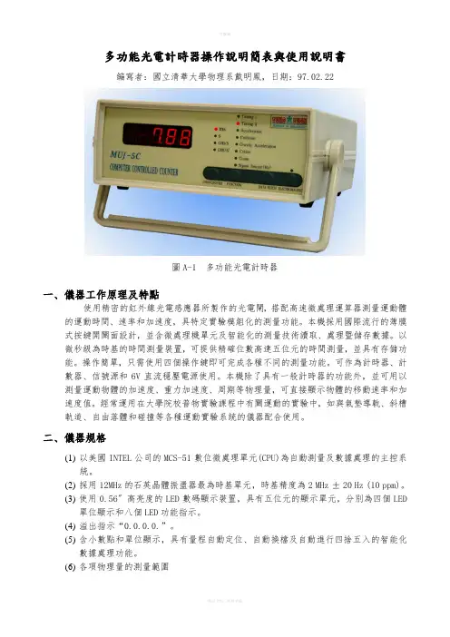
多功能光電計時器操作說明簡表與使用說明書編寫者:國立清華大學物理系戴明鳳,日期:97.02.22圖A-1 多功能光電計時器一、儀器工作原理及特點使用精密的紅外線光電感應器所製作的光電閘,搭配高速微處理運算器測量運動體的運動時間、速率和加速度,具特定實驗模組化的測量功能。
本機採用國際流行的薄膜式按鍵開關面設計,並含微處理機單元及智能化的測量技術讀取、處理暨儲存數據。
以微秒級為時基的時間測量裝置,可提供精確位數高達五位元的時間測量,並具有存儲功能。
操作簡單,只需使用四個操作鍵即可完成各種不同的測量功能。
可作為計時器、計數器、信號源和6V直流穩壓電源使用。
本機除了具有一般計時器的功能外,並可用以測量運動物體的加速度、重力加速度、周期等物理量,可直接顯示物體的移動速率和加速度值。
經常運用在大學院校普物實驗課程中有關運動的實驗中,如與氣墊導軌、斜槽軌道、自由落體和碰撞等各種運動實驗系統的儀器配合使用。
二、儀器規格(1)以美國INTEL公司的MCS-51數位微處理單元(CPU)為自動測量及數據處理的主控系統。
(2)採用12MHz的石英晶體振盪器最為時基單元,時基精度為2 MHz ±20 Hz (10 ppm)。
(3)使用0.56〞高亮度的LED數碼顯示裝置,具有五位元的顯示單元,分別為四個LED單位顯示和八個LED功能指示。
(4)溢出指示“0.0.0.0.”。
(5)含小數點和單位顯示,具有量程自動定位、自動換檔及自動進行四捨五入的智能化數據處理功能。
(6)各項物理量的測量範圍(a)速度範圍為:0.00~1000.0 cm/s(b)加速度範圍為:±0.00~1200.0 cm/s2(c)計數範圍為:0~99999(d)計時範圍為:0.00 ms~999.99 s(e)0.01 ms數量級以上確保五位有效數字顯示。
(7)可存儲20個時間數據,在周期測量中存儲21個時間數據(前20個振動周期和一個n次(最多9999周期)振動的累加時間總和。

计时表的使用方法
嘿,大家知道计时表吗?这玩意儿可太有用啦!
那计时表到底该咋用呢?其实很简单啦!首先,找到计时表上的开始/停止按钮,轻轻一按,计时就开始啦。
然后,在需要结束计时的时候,再按一下这个按钮,计时就停止咯。
哎呀,是不是超级简单呀!但这里可有几个注意事项哦!比如要确保计时表的电量充足呀,不然关键时刻掉链子可就麻烦啦!还有就是要小心别误按到其他按钮,不然数据可就乱啦!在操作的时候可得打起十二分精神呢!
在使用计时表的过程中呀,安全性和稳定性那也是相当重要的呢!就像走钢丝一样,得稳稳当当的才行呀!质量好的计时表一般不会出现啥大问题,不会突然就失灵或者出错,能让我们放心大胆地使用呢。
那计时表都有啥应用场景和优势呀?那可多啦去啦!比如说在运动比赛中,能准确记录运动员的成绩呢。
在厨房里,也能帮我们精确掌握烹饪时间呀。
优势嘛,它小巧轻便,携带方便呀,随时随地都能拿出来用呢!而且操作简单,一学就会呀,多棒呀!
我就给大家说个实际案例吧。
上次我参加一个烘焙比赛,要做一个蛋糕,规定时间内完成。
我就用计时表来计算每一步的时间,哎呀,可帮了大忙啦!让我能有条不紊地完成每一个步骤,最后做出了超级美味的蛋糕呢,还拿了个好名次呢!这就是计时表的实际应用效果呀,真的超赞呢!
计时表就是这么好用呀,能给我们的生活带来很多便利呢,大家赶紧去试试吧!。
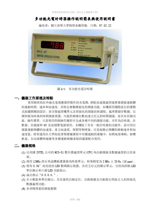
多功能光電計時器操作說明簡表與使用說明書編寫者:國立清華大學物理系戴明鳳,日期:97.02.22圖A-1 多功能光電計時器一、儀器工作原理及特點使用精密的紅外線光電感應器所製作的光電閘,搭配高速微處理運算器測量運動體的運動時間、速率和加速度,具特定實驗模組化的測量功能。
本機採用國際流行的薄膜式按鍵開關面設計,並含微處理機單元及智能化的測量技術讀取、處理暨儲存數據。
以微秒級為時基的時間測量裝置,可提供精確位數高達五位元的時間測量,並具有存儲功能。
操作簡單,只需使用四個操作鍵即可完成各種不同的測量功能。
可作為計時器、計數器、信號源和6V直流穩壓電源使用。
本機除了具有一般計時器的功能外,並可用以測量運動物體的加速度、重力加速度、周期等物理量,可直接顯示物體的移動速率和加速度值。
經常運用在大學院校普物實驗課程中有關運動的實驗中,如與氣墊導軌、斜槽軌道、自由落體和碰撞等各種運動實驗系統的儀器配合使用。
二、儀器規格(1)以美國INTEL公司的MCS-51數位微處理單元(CPU)為自動測量及數據處理的主控系統。
(2)採用12MHz的石英晶體振盪器最為時基單元,時基精度為2 MHz ±20 Hz (10 ppm)。
(3)使用0.56〞高亮度的LED數碼顯示裝置,具有五位元的顯示單元,分別為四個LED單位顯示和八個LED功能指示。
(4)溢出指示“0.0.0.0.”。
(5)含小數點和單位顯示,具有量程自動定位、自動換檔及自動進行四捨五入的智能化數據處理功能。
(6)各項物理量的測量範圍(a)速度範圍為:0.00~1000.0 cm/s(b)加速度範圍為:±0.00~1200.0 cm/s2(c)計數範圍為:0~99999(d)計時範圍為:0.00 ms~999.99 s(e)0.01 ms數量級以上確保五位有效數字顯示。
(7)可存儲20個時間數據,在周期測量中存儲21個時間數據(前20個振動周期和一個n次(最多9999周期)振動的累加時間總和。

Switches&PilotLightsDisplayLightsRelays&SocketsTerminalBlocksCircuitBreakersT iming Diagrams OverviewGuide to Reading Timing Function DiagramsPower PowerStart Input Start Input1. If power is disconnected during actual timing, most electronic timers reset to thepreset time, ready for the re-application of supply voltage(except for GT3F “true OFF Delay”).2. NO = Normally open.3. NC = Normally closed.Timing Function Diagrams OverviewON-Delay 1 (power start)When voltage is applied to the coil, the relay contacts remain in the off stateand the set time begins. When the set time has elapsed, the relay contactstransfer to the on state. The contacts remain in the on state until the timer isreset. The timer is reset by removing the coil voltage. Applicable models: RTE-P(B)1, GT3A-1, -2, -3, GT3D-1, -2, -3, -4, and GE1A.PowerOutputInterval 1 (power start)When voltage is applied to the coil, the relay contacts transfer immediately tothe on state and the set time begins. When the set time has elapsed, the relaycontacts transfer to the off state. The contacts remain in the off state until thetimer is reset. The timer is reset by removing the coil voltage. Applicable models:RTE-P(B)1, GT3A-1, -2, -3, and GT3D-1, -2, -3, -4.PowerOutputON-Delay 2 (signal start)Voltage is applied to the coil at all times. When a start input is supplied, therelay contacts remain in the off state and the set time begins. When the settime has elapsed, the relay contacts transfer to the on state. The contactsremain in the on state until the timer is reset. The timer is reset by applying areset input or by removing the coil voltage. Applicable models: GT3A-4, GT3D-4and RTE-P(B) 2.Start InputOutputInterval 2 (signal start)Voltage is applied to the coil at all times. When a start signal is supplied, therelay contacts transfer immediately to the on state and the set time begins.When the set time has elapsed, the relay contacts transfer to the off state. Thecontacts remain in the off state until the timer is reset. The timer is reset by ap-plying a reset input or by removing the coil voltage. Applicable models: GT3A-5and GT3D-4.Start InputOutput1. T = set time, T’ = shorter than set time, Ts = one shot output time2. For more detailed timing diagrams, see specifi cations for individual timer models.Switches & Pilot LightsDisplay LightsRelays & SocketsTerminal BlocksCircuit BreakersCycle 1 (power start, OFF fi rst)When voltage is applied to the coil, the contacts remain in the off state and the set time begins. At the end of the set time, the contacts transfer to the on state and remain in the on state until the set time elapses. The timer cycles between the two states until power is removed from the coil. Removing the coil voltage resets the timer. The set time for both the on state and the off state is thesame. Applicable models: GT3A-1, -2, -3, GT3D-1, -2, -3, -4 and RTE-P(B)1.PowerOutputCycle 3 (power start, ON fi rst)When voltage is applied to the coil, the contacts immediately transfer to the on state and the set time begins. At the end of the set time, the contacts transfer to the off state and remain in the off state until the set time elapses. The timer cycles between the two states until power is removed from the coil. Removing the coil voltage resets the timer. The set time for both the off state and the on state is the same. Applicable models: GT3A-1, -2, -3, GT3D-1, -2, -3, -4 andRTE-P(B)1.PowerOutputOne Shot 1 (signal start, retriggerable)Voltage is applied to the coil at all times. When a start signal is supplied, the contacts immediately transfer to the on state and the set time begins. If another start signal is supplied (before set time has elapsed) the set time restarts, as the contacts remain in the on state . Successive pulses at a frequency greater than the set time will cause the contacts to remain in the “On state ” indefi nitely. When the set time has elapsed the contacts transfer back to the off state . The contacts remain in the off state until the next start signal is supplied (no reset is necessary). The timer can be reset by application of a reset input orby removing coil voltage. Applicable models: GT3A-6 and GT3D-4.Start InputOutputCycle 2 (signal start, OFF fi rst)Voltage is applied to the coil at all times. When a start signal is supplied, the relay contacts remain in the off state and the set time begins. At the end of the set time, the contacts transfer to the on state and remain in the on state until the set time elapses. The timer cycles between the two states until the timer is reset. The set time for both the on state and the off state are the same. The timer is reset by application of a reset input or by removing coil voltage. Ap-plicable models: GT3A-4, GT3D-4 and RTE-P(B) 2.Start InputOutputOne Shot Cycle (signal start)Voltage is applied to the coil at all times. When a start signal is supplied, the con-tacts remain in the off state and the set time begins. At the end of the set time, the contacts transfer to the on state and remain in the on state for the set time. After the set time has elapsed, the contacts return to the off state . The contacts remain in the off state until the timer is reset. The timer is reset by application ofa reset input or by removing coil voltage. Applicable models: GT3A-5 and GT3D-4.Start InputOutputOne Shot 2 (signal start)Voltage is applied to the coil at all times. When a start signal is supplied, the contacts immediately transfer to the on state and the set time begins. If another start signal is supplied (before set time has elapsed), the set time will not be affected. When the set time has elapsed, the contacts transfer back to the off state . The contacts remain in the off state until the next start signal is supplied (no reset is necessary). The timer can be reset by application of a reset input orby removing coil voltage. Applicable models: GT3A-6, GT3D-4, and RTE-P(B)2.Start InputOutput1. T = set time, T’ = shorter than set time, Ts = one shot output time2. For more detailed timing diagrams, see specifi cations for individual timer models.Switches&PilotLightsDisplayLightsRelays&SocketsTerminalBlocksCircuitBreakersSignal ON/OFF-Delay 1Voltage is supplied to the coil at all times. When a maintained start signal issupplied, the contacts immediately transfer to the on state and the set time be-gins. When the set time has elapsed, the contacts transfer to the off state. Thecontacts remain in the off state until the start signal is removed. The contactstransfer back to the on state and remain in the on state for the set time. Whenthe set time has elapsed, the contacts transfer to the off state and remain in theoff state until the start signal is supplied again (no reset is necessary). The timeris reset by application of a reset input or by removing coil voltage. Applicablemodels: GT3A-4, GT3D-4 and RTE-R(B)2.Start InputOutputSignal ON/OFF-Delay 3Voltage is supplied to the coil at all times. When a momentary start signal issupplied, the contacts remain in the off state and the set time begins. When theset time has elapsed, the contacts transfer to the on state. The contacts remainin the on state until another momentary input is supplied. The contacts thenremain in the on state for the set time. When the set time has elapsed, the con-tacts transfer to the off state and remain in the off state until the start signal issupplied again (no reset is necessary). The timer is reset by application of a resetinput or by removing coil voltage. Applicable models: GT3A-6 and GT3D-4.Start InputOutputOne Shot ON-Delay (signal start)When voltage is applied to the coil, the preset time is initiated and the contactsremain in the off state for the preset time. Following the preset time, thecontacts transfer to the on state, and remain in the on state until the start inputis supplied. Following the start input, the contacts transfer to the off state forthe preset time. After the preset time has elapsed, the contacts transfer back tothe on state and remain there until either the next start input is supplied or thetimer is reset. The timer can be reset by either a reset input or removal of thecoil voltage. Applicable models: GT3A-6 and GT3D-4.Start InputOutputSignal ON/OFF-Delay 2Voltage is supplied to the coil at all times. When a maintained start signal issupplied, the contacts remain in the off state and the set time begins. Whenthe set time has elapsed, the contacts transfer to the on state. The contactsremain in the on state until the start signal is removed. Once the start signalis removed, the contacts remain in the on state and the set time begins again.Once the set time has elapsed, the contacts transfer back to the off state. Thetimer is ready for the next start signal. The timer is reset by the application of areset signal or removal of power. Applicable models: GT3A-5 and GT3D-4.Start InputOutputSignal OFF-Delay 1Voltage is applied to the coil at all times. When a start signal is supplied, thecontacts immediately transfer to the on state. The set time begins when thestart signal is removed. When the set time has elapsed, the contacts transferto the off state. The contacts remain in the off state until the next start signal issupplied (no reset is necessary). The timer can be reset by application of a resetinput or by removing coil voltage. Applicable models: RTE-P(B)2, GT3A-4, andGT3D-4.Start InputOutputSignal OFF-Delay 2Voltage is applied to the coil at all times. When a maintained start signal is sup-plied, the contacts remain in the off state. When the “start signal is removed”,the contacts transfer to the “On state” and the set time begins. When the settime has elapsed, the contacts transfer back to the off state. They remain inthe off state until the next start signal is supplied (no reset is necessary. Thetimer can be reset by application of a reset input or by removing coil voltage.Applicable models: GT3A-5 and GT3D-4.Start InputOutput1. T = set time, T’ = shorter than set time, Ts = one shot output time2. For more detailed timing diagrams, see specifi cations for individual timer models.Switches & Pilot LightsDisplay LightsRelays & SocketsTerminal BlocksCircuit BreakersON-Delay One-Shot Output 1 (signal start)Voltage is applied to the coil at all times. When a momentary start signal is sup-plied, the contacts remain in the off state and the preset time begins. Following the preset time, the contacts transfer to the on state and remain in the on statethere until timer is reset. The timer can be reset by a reset input, removal of the coil voltage or removal of start input. Applicable model: GT3D-8.Start InputOutputSequential Start (power start)When voltage is applied to the coil, both contacts remain in the OFF state and the set time, T1, begins. When T1 has elapsed, output 1 comes on and T2 begins. When T2 has elapsed, output 2 comes on. Both outputs remain on until power is removed from the coil. Applicable model: GT3W-A.Start InputOutputCycle One-Shot Output (signal start)Voltage is applied to the coil at all times. When a momentary start signal is sup-plied, the contacts remain in the off state and the preset time begins. Following the preset time, the contacts transfer to the on state . The contacts remain in the on state for the one-shot preset time. After the one-shot preset time has elapsed, the contacts transfer back to the off state . The contacts remain in the off state for the preset time minus the one-shot preset time. The timer cycles between on and off states until the timer is reset by a reset input or removal ofthe coil voltage. Applicable model: GT3D-8.Start InputOutputTrue Power-OFF DelayWhen voltage is applied, output comes on immediately; when voltage is removed from the coil, the timer begins timing (internal capacitors power the timing circuit). When time has expired, contacts transfer back to the OFF state. If power is reapplied before the elapsed time has expired, the timing function will reset back to the starting point. Applicable models: GT3F-1, 2.Start InputOutputRecycler Outputs (power start)When voltage is applied to the coil, both contacts remain in the off state and time T1 begins. When T1 has elapsed, both contacts transfer to the ON state and T2 begins. When T2 has elapsed, both contacts transfer back to the OFF state and T1 begins again. The cycle continues until power is removed, at whichtime both contacts transfer back to the OFF state. Applicable model: GT3W-A.Start InputOutput1. T = set time, T’ = shorter than set time, Ts = one shot output time2. For more detailed timing diagrams, see specifi cations for individual timer models.。
计时器的操作方法
计时器的操作方法包括:
1. 设置时间:通过按下“设置”按钮或者按下时间调整按钮(如+、-按钮)来设置倒计时时间或者计时时间。
2. 启动计时器:按下“开始”按钮或者其他指定按钮来启动计时器。
倒计时模式下,计时器将倒计时至零;计时模式下,计时器将从零开始计时。
3. 暂停计时器:按下“暂停”按钮或者其他指定按钮来暂停计时器。
在暂停状态下,计时器将停止计时,时间不会继续减少或者增加。
4. 继续计时器:按下“继续”按钮或其他指定按钮来继续计时器。
在继续状态下,计时器将恢复计时,时间会继续减少或者增加。
5. 重置计时器:按下“重置”按钮或者其他指定按钮来重置计时器。
倒计时模式下,计时器将恢复到初始设定的时间;计时模式下,计时器将恢复到0。
6. 报警功能:一些计时器具备报警功能,当计时器倒计时或者计时结束时,会发出声音或者震动提醒用户。
可以通过设置或者调整报警参数来调整报警的方式和效果。
需要注意的是,不同类型的计时器的操作方法可能有所差异,具体操作方法可能会因计时器的功能和设计而异。
因此在使用具体计时器时,还需阅读并遵循相应计时器的说明书或者使用手册中给出的操作方法。
光电计时器的使用方法《光电计时器的使用方法:超有趣秘籍大放送!》嘿,宝子们!今天我来给你们分享光电计时器这个超酷小玩意儿的使用方法,就像给你们分享我珍藏多年的美食配方一样,绝对独家哦!首先呢,咱得找到光电计时器。
这就好比你要做饭,得先找到锅一样重要。
光电计时器一般长得像个小盒子,上面有一些按钮和显示屏,有的可能还有小灯在闪呢,就像小眼睛一眨一眨的,特别可爱。
你可别把它当成什么外星小物件,其实它操作起来超简单的。
拿到光电计时器后,第一步就是给它找个合适的位置。
这位置啊,就像给人找房子一样讲究。
它得放在光线比较好的地方,但又不能让阳光直射它的眼睛(也就是传感器啦),不然就像你在大太阳底下睁不开眼一样,它也会“晕头转向”,导致计时不准确。
我就有一次,傻愣愣地把它放在窗台正对着太阳的地方,结果测出来的数据那叫一个离谱,就像说一个人一天能跑一万公里一样不靠谱。
所以呢,找个光线均匀、柔和的地方是关键,比如桌子的一角,或者靠着墙边的架子上。
接下来,咱要看看这个光电计时器的电源。
有的是用电池的,就像给小玩具装电池一样简单。
打开后盖,把电池按照正负极放好,就像把鞋子左右脚穿对一样自然。
要是你放反了,它可不会工作哦,就像你把左脚的鞋子穿到右脚上,走起路来肯定别扭。
还有些光电计时器是可以充电的,那就找到充电线,把它插到对应的接口上,就像给手机充电一样,等它吃饱电就可以开始工作啦。
现在呢,我们就可以开始设置计时模式了。
这光电计时器就像一个小管家,你得告诉它要怎么干活。
一般它的按钮都有标记,像“开始/停止”“复位”“模式选择”这些。
如果我们要简单地计个时,就像你煮个泡面想知道煮了多久一样,那就按下“模式选择”按钮,找到计时模式。
这个过程就像你在菜单里找自己想吃的菜一样,要耐心一点哦。
找到计时模式后,再看看显示屏上的数字是不是归零了,如果不是,就按一下“复位”按钮,让它回到最初的状态,就像把棋盘重新摆好准备下一盘棋一样。
然后就是正式开始计时啦!按下“开始/停止”按钮,这时候光电计时器就像一个起跑线上的运动员,听到枪响就开始冲刺了。
多功能表操作说明Acuvim390、330、327操作说明:1.查看电流、电压参数:V/A键,实现查看和翻屏功能2.查看功率参数:,实现查看系统有功功率P(KW)、无功功率Q(KVar)、视在功率S (KVA)3.查看电度:,实现查看系统有功电能Ep(KWh)、无功电能Eq(Kvarh)、视在电能Es(KVAh),其中常规看的电度为:系统有功电能Acuvim188操作说明:1.查看电流、电压、功率参数:V/A键,实现查看和翻屏功能2.查看电度:F键,实现查看系统有功电能Ep(KWh),其中常规看的电度为:系统有功电能仪表常见问题排查(确保接线正确情况下):1.电流测量不准情况:检测CT设置参数是否跟实际CT额定参数一致2.电压测量不准情况:检测pT设置参数是否跟实际pT额定参数一致3.电度测量不准情况:首先检测电流、电压测量参数是否正确,否则调整相应参数设置然后检查实际接线与系统设置接线方式是否正确,否则调整相应参数设置系统参数设置:Acuvim390、330、327设置:同时按F和V/A键,进入密码登陆界面,出厂默认密码为0000,如下图:按V/A键翻至仪表接线方式设定页。
“仪表接线方式”可设定为“3Ln”、“3LL”、“2LL”和“1Ln”。
相关内容请参考用户使用手册。
如下图:接线方式设定为3Ln。
使用“↑”键或者“↓”键进行接线方式切换。
按“V/A”键确认并进入下一屏设定页。
按V/A键进入系统参数设置,然后使用V/A键翻屏,翻到第四屏(PT设置界面),设置PT一次侧额定电压值,如下图按V/A键翻到如下界面,设置PT二次侧额定电压值(电压直接接入情况下,设定值与一次侧相同)按V/A键翻到如下界面,设置CT一次侧额定电流值,设定值应与现场CT一侧额定值一致按V/A键翻到如下界面,设置CT二次侧额定电流值,仪表出厂前根据客户要求设定5A或1A的固定值,其值不可更改AO模拟量的参数设置:在系统参数设置模式下,同时按F和按键,进入如下界面:模拟量AO1跟随量的设定界面:(根据仪表型号不同,其具体功能也不同,选定恰当的变送跟随量,如下表)按V/A键进入下图设置界面,为满足不同用户的需求,Acuivm 300 扩展AO提供变送范围选择。
多功能电力仪表使用手册使用手册USER MANUAL目录一、多功能电力仪表使用手册 (2)1、概述 (2)2、技术参数 (2)3、编程和使用 (3)测量显示 (3)编程操作 (5)4、通迅 (10)通迅报文举例 (11)MODBUS地址信息表 (11)5、功能输出 (13)二、多功能三相电压、三相电流、有功电度、无功电度表使用手册 (14)1、概述 (14)2、使用 (14)三、多功能有功电度、无功电度使用手册 (16)4、概述 (16)5、使用 (16)四、多功能三相电流、有功电度表使用手册 (18)1、概述 (18)2、使用 (18)五、接线图 (19)120*120接线图 (20)96*96接线图 (21)80*80接线图 (22)72*72接线图 (23)六、常见问题及解决方法: (24)多功能电力仪表--使用手册一、概述多功能电力仪表是一种具有可编程测量、显示、数字通讯和电能脉冲输出等功能的多功能电力仪表,能够完成电量测量、电能计量、数据显示、采集及传输,可广泛应用变电站自动化,配电自动化、智能建筑、企业内部的电能测量、管理、考核。
测量精度为0.5级、实现LED 现场显示和远程RS-485数字接口通讯,采用MODBUS-RTU通讯协议。
外形代号外形尺寸(mm)测量显示辅助功能42方形120*120*112 相电压、线电压、电流、总有功功率、总无功功率、总功率因素、总视在功率、频率、有功电能、无功电能3排LED分页显示电能脉冲输出数字通讯96方形96*96*1126方形80*80*76数字通讯72方形72*72*105性能参数输入测量显示网络三相三线、三相四线电压额定值AC100V、400V(订货时说明)过负荷持续:1.2倍瞬时:10倍/10s功耗<1VA(每相)阻抗>500kΩ精度RMS测量,精度等级0.5电流额定值AC1A、5A(订货时请说明)过负荷持续:1.2倍瞬时:10倍/10s功耗<0.4VA(每相)阻抗<2mΩ精度RMS测量,精度等级0.5频率40~60Hz,精度0.1Hz功率有功、无功、视在功率,精度0.5级电能四象限计量,有功精度0.5级,无功精度1级显示可编程、切换、循环(LED)显示电源频率AC/DC 85~270V 功率≤5VA输出电能RS-485、MODBUS-RTU协议显示2路电能脉冲输出,光耦继电器(6方形、72方形除外)环境工作范围-10~55℃功耗-20~75℃安全耐压输入/电源>2kV,输入/输出>2kV,电源/输出>1kV 绝缘输入、输出、电源对机壳>5MΩ1)辅助电源:多功能电力仪表具备通用的(AC/DC)电源输入接口,若不作特殊声明,提供的是AC/DC85~270V电源接口的标准产品,保证所提供的电源适用于该系列的产品,以防止损坏产品。
1•Time range 0.1 s to 100 h •Knob selection of time range •Knob-adjustable time setting •Repeatability: ≤0.2%•Output: 5 A SPDT relay•For mounting on DIN-rail in accordance with DIN/EN 50 022•17.5 mm DIN-rail housing•Combined AC and DC power supply•LED indication for relay status and power supply ONMulti-voltage d elay on release timer with 7 knob selectable time ranges with-in 0.1 s and 100 h.For mounting on DIN-rail.TimersDelay on Release Type DBA52Product DescriptionType SelectionMounting Output Housing Supply: 24 VDC and 24 to 240 VAC DIN-railSPDTD-HousingDBA 52 C M24Time SpecificationsOutput SpecificationsSupply Specifications2DimensionsOperating DiagramDBA52The relay operates as soon as the trigger contact is close d . The time perio dbegins when the trigger contact is opened. The relay releases at the end of the set d elay time or when the power supply is disconnect-ed. The relay operates again when the input contact is closed again. If it is closed before the end of the d elay time the relay keeps ON, anew time period begins as soon as the trigger contact is opened again.Additional LoadIt's possible to wire an addi-tional loa d (i.e. a relay)between pins Y1 and A2driven by the trigger contactwithoutd amaging the d evice (see wiring diagram).Yellow LED working mode Timing: Slow blinking Relay ON: See operation diagrams Incorrect knobs position:Fast blinking General SpecificationsTime SettingMode of OperationWiring DiagramCentre knob:Time setting on relative scale: 1 to 10 with respect to the chosen range.Lower knob:Setting of time range.。
多功能光電計時器操作說明簡表與使用說明書編寫者:國立清華大學物理系戴明鳳,日期:97.02.22圖A-1 多功能光電計時器一、儀器工作原理及特點使用精密的紅外線光電感應器所製作的光電閘,搭配高速微處理運算器測量運動體的運動時間、速率和加速度,具特定實驗模組化的測量功能。
本機採用國際流行的薄膜式按鍵開關面設計,並含微處理機單元及智能化的測量技術讀取、處理暨儲存數據。
以微秒級為時基的時間測量裝置,可提供精確位數高達五位元的時間測量,並具有存儲功能。
操作簡單,只需使用四個操作鍵即可完成各種不同的測量功能。
可作為計時器、計數器、信號源和6V直流穩壓電源使用。
本機除了具有一般計時器的功能外,並可用以測量運動物體的加速度、重力加速度、周期等物理量,可直接顯示物體的移動速率和加速度值。
經常運用在大學院校普物實驗課程中有關運動的實驗中,如與氣墊導軌、斜槽軌道、自由落體和碰撞等各種運動實驗系統的儀器配合使用。
二、儀器規格(1)以美國INTEL公司的MCS-51數位微處理單元(CPU)為自動測量及數據處理的主控系統。
(2)採用12MHz的石英晶體振盪器最為時基單元,時基精度為2 MHz ±20 Hz (10 ppm)。
(3)使用0.56〞高亮度的LED數碼顯示裝置,具有五位元的顯示單元,分別為四個LED單位顯示和八個LED功能指示。
(4)溢出指示“0.0.0.0.”。
(5)含小數點和單位顯示,具有量程自動定位、自動換檔及自動進行四捨五入的智能化數據處理功能。
(6)各項物理量的測量範圍(a)速度範圍為:0.00~1000.0 cm/s(b)加速度範圍為:±0.00~1200.0 cm/s2(c)計數範圍為:0~99999(d)計時範圍為:0.00 ms~999.99 s(e)0.01 ms數量級以上確保五位有效數字顯示。
(7)可存儲20個時間數據,在周期測量中存儲21個時間數據(前20個振動周期和一個n次(最多9999周期)振動的累加時間總和。
(8)脈沖信號源有1 Hz、10 Hz、100 Hz、1000 Hz、10000 Hz等五檔,輸出幅度近5V。
(9)提供6V直流電壓及0.5A的直流穩壓電源輸出(10)提供兩個紅外光電傳感器(11)配有可供氣墊導軌和自由落體儀器使用的四個光電閘信號輸入插座。
(12)配有供斜槽軌道和自由落體儀實驗系統之電磁鐵控制插座。
(13)工作條件:●電源:AC 110V ± 10%,50 Hz~60 Hz。
●環境溫度:-10℃~ 40℃●相對濕度:在40℃時,低於85%。
●工作時間:連續工作(14)外形尺寸:約230 mm × 210 mm × 100 mm(15)重量:約1.5 Kg三、面板說明(1)前面板說明:見圖A-2,、、和等所有按鍵均為循環式的切換開關。
MU J-5C計時計數測速儀S1 計時1S2 計時2a 加速度Pzh 碰撞G 重力加速度T 周期J 計數Sg1 信號源mssCm/sCm/s轉換功能取數電磁鐵12347568五位元LED顯示列測量單位指示燈數值轉換鍵功能轉換指示燈功能選擇/復位鍵取數鍵電磁鐵開關指示燈電磁鐵開關鍵圖A-2 MUJ-5C多功能光電計時器面板說明五位元LED顯示列:顯示測量的結果測量單位指示燈:依所選定的測量功能,顯示所測得之數據的單位,如ms, s , cm/s, cm/s等四個時間和速率的單位。
轉換鍵(Changeover):當選擇計時、加速度和碰撞等測量功能時,在1秒內迅速按轉換鍵,可交替地選擇測量各種不同物理量。
光電閘的檔光片寬度有1.0 cm、3.0cm、5.0cm、10.0cm等四個不同的寬度選擇,可經由轉換鍵的切換選擇所需的寬度。
使轉換鍵的切換時間超過1 sec ,即可選擇檔光片的寬度設定。
功能鍵(Function):如按下功能鍵前,光電閘若遮過光,則可先按一次功能鍵進行歸零。
若光電閘沒遮過光,請按功能鍵選擇擬測量的功能。
取數鍵(Data Fetch):在計時1 (S1)、計時2 (S2)、周期(T)功能時,儀器可自動存入前20個測量值,按下取數鍵,可顯示存入的紀錄值。
當顯示「E n」表示將顯示存入的第n值。
電磁鐵開/關指示燈:顯示電磁鐵處於吸合或鬆離的狀態,當紅色LED亮時,表示電磁鐵為開啟的吸合狀態;LED不亮時,則表示電磁鐵為關閉狀態。
電磁鐵開關鍵(Electromagnet):控制電磁鐵的吸合和鬆離(鍵上LED顯示暗)的切換鍵,當按鍵上的電磁鐵開/關紅色LED指示燈亮時,表示有電磁鐵為開啟的吸合狀態;LED不亮時,則表示電磁鐵為關閉,處於無電磁力的狀態。
(2)後面板O NO FF12347568P1光電閘信號插座P2光電閘信號插座信號源輸出插座電磁鐵信號插座6V直流輸出插座電源保險絲座電源開關電源線圖A-2 MUJ-5C多功能光電計時器背面板說明四、多功能光電計時器使用說明簡表多功能光電計時器使用簡表(永原科學儀器公司製造,型號A04-153)•測量前先按下Changeover (> 1 sec),選擇檔光片寬度•測量後可迅速(< 1 sec) 按下Changeover,可使顯示器的顯示值切換為時間或速度•數據顯示後, 可按Function鍵歸零重新實驗。
歸零後再按一次Function鍵,可跳入下一功能選擇功能應用例擋光板光電閘時間數據顯示(秒/毫秒)Timing I 拋體初速轉動週期▅P1或P2•同一光電門擋光時程/速度•按Data Fetch顯示20組記錄Timing II 重物下落已知高度時間▅P1或P2•以▅擋光片得同一光電門兩次擋光的時距•以擋光片得同一光電門一次擋光的時程--- Changeover選擇時間速度--- Changeover選擇速度•可按Data Fetch顯示20組記錄Acceleration 直線等加速度運動由P1至P2•Changeover選擇時間P1的擋光時程P2的擋光時程P1至P2的擋光時程•Changeover選擇速度P1的擋光速度P2的擋光速度P1至P2的加速度Collision碰撞運動P1或P2•Changeover選擇速度顯示各光電門各來回1至3次擋光片之速度•Changeover選擇時間顯示各光電門各來回1至3次擋光片之時間Gravity Acceleration 自由落體●由電磁鐵至P1~P4準備好後,按下Electromagnet顯示電磁鐵下端至P1/P2/P3/P4的時程Cycle單擺複擺簡諧運動●▅P1或P2•Changeover預設週期數100以內.實驗完顯示總時間,再按Data Fetch顯示最後20週期時間.•不預設週期數而直接測量直到結束可顯示測量週期序直到結束.按Changeover顯示總時間,再按DataFetch顯示最後20週期時間實Count轉動次數▅P1或P2•顯示遮光次數Signal Source 信號源輸出插座•按Changeover可輸出頻率為:1、10、100、1000、10000的方波信號,單位為HzDC Power DC6V輸出插座•任何時間可輸出五、測量功能1.Timing I:一般遮光時程測量2.Timing II:二次遮光時距3.Acceleration:直線運動體單點瞬時速度測量及雙點間加速度值的計算4.Collision:碰撞實驗中,兩運動體碰撞前後的瞬時速度測量5.Gravity Acceleration:自由落體下落至不同高度的時間測量6.Cycle:單擺計次、累計時間、單次擺動週期記錄及顯示7.Count:計數遮光次數8.Signal Source:信號產生器,可供其它實驗使用。
六、操作方法(1)測量單位:(a)ms:1/1000秒,計時單位(b)s:秒,計時單位(c)m/s:公分/秒,速度單位(d)cm/s2:公分/秒平方,加速度單位(2)各種物理量的測量1.Timing I (計時1 , S1):遮光時程測量測量光電閘的擋光時間,可連續測量,並自動存入前20個所測得的數據。
按下取數鍵可查看儲存於計數器內的數據。
2.Time II (計時2, S2):二次遮光時間間距測量測量光電閘兩次擋光的間隔時間,可連續測量。
並自動存入前20個數據,按下取數鍵可查看所量得的數據。
3.Acceleration (加速度, a)測量測量帶有凹形擋光片的滑行器通過相鄰兩個光電閘的速度,以及通過此兩光電閘間之段路程所需的時間,可連接2至4個光電閘。
在此測量模態時,本計時器的顯示面版上會循環顯示下列數據:1 第一個光電管××××× 第一個光電管測量值(T1/V1)2 第二個光電管××××× 第二個光電管測量值(T2/V2)1~2 第一至第二光電管××××× 第一至第二光電管測量(T1~2/a)如接有第3、4個光電閘,則除顯示上測量數據外,並繼續顯示第3個光電管、第4個光電管及2~3、3~4段的測量值,如下所列。
××××× 第三個光電管測量值(T3/V3)2~3 第二至第三光電管××××× 第二至第三光電管測量(T2~3/a)4 第四個光電管××××× 第四個光電管測量值(T4/V4)3~4 第三至第四光電管××××× 第三至第四光電管測量(T3~4/a)按功能鍵清〞0〞,可進行另一系列新的測量。
4.Collision (碰撞, Pzh):等質量與不等質量間的碰撞實驗測量在計時器後面板的P1、P2接頭各接一只光電管,兩只滑行器上裝好相同寬度的凹形擋光片和碰撞彈簧,讓滑行器從氣軌兩端向中間運動,各自通過一個光電閘後相撞。
做完實驗,會循環顯示下列數據:P1.1 第一次通過P1光電管×××××第一次通過P1光電管的遮光時間測量值P1.2 第二次通過P1光電管×××××第二次通過P1光電管的遮光時間測量值P2.1 第一次通過P2光電管×××××第一次通過P2光電管的遮光時間測量值P2.2 第二次通過P2光電管×××××第二次通過P2光電管的遮光時間測量值(1)如滑塊通過P1光電管三次,但僅通過P2光電管一次,則計時器將不顯示P2.2而顯示P1.3,表示物體第三次通過P1光電管的第三次遮光時間(2)如滑塊通過P2光電管三次,通過P1光電管一次,本機將不顯示P1.2而顯示P2.3,表示第三次通過P2光電管的第三次遮光時間。