Software Reliability Measurements in N-Version Software Execution Environment
- 格式:pdf
- 大小:68.29 KB
- 文档页数:25

calibration standards 校Calibration Standards: Ensuring Precision and Accuracy in MeasurementIntroduction:Accurate and precise measurements are vital in various industries such as manufacturing, healthcare, and scientific research. These measurements form the basis for making informed decisions, ensuring quality control, and achieving regulatory compliance. However, instruments and devices used for measurements can experience drift or deterioration over time, leading to inaccurate results. To address this issue, calibration standards have been developed to maintain the accuracy and reliability of measuring instruments. In this article, we will explore what calibration standards are, how they work, and their importance in various fields.What are Calibration Standards?Calibration standards are reference instruments or materials that are used to calibrate or align measurement tools to a known andtraceable standard, ensuring accurate and reliable results. These standards are developed and maintained by recognized national and international bodies such as the National Institute of Standards and Technology (NIST) in the United States or the International Organization for Standardization (ISO). Calibration standards can encompass various types of measurements, including temperature, pressure, length, mass, and electrical parameters.The Calibration Process:The calibration process involves comparing the measurements of an instrument with a known standard to determine any deviations or inaccuracies. Let's take a step-by-step look at how this process works:1. Selecting the Calibration Standard: The first step is to identify the appropriate calibration standard that matches the measurement range and precision required. For example, if calibrating a thermometer, a certified reference temperature probe will be needed.2. Preparing the Instrument: Before calibration, the instrument isusually cleaned, inspected for physical damage, and, if necessary, adjusted to ensure it is in proper working condition.3. Performing the Calibration: The measurement readings of the instrument are compared with those of the calibration standard. The comparison may involve multiple measurements at different points to account for variations or inconsistencies.4. Calculating the Deviation: The deviation between the instrument's measurements and the calibration standard is calculated, typically in terms of the error or difference from the reference standard.5. Adjusting the Instrument: If the deviation is within an acceptable range, the instrument may require adjustment to align its measurements with the calibration standard. This adjustment is carried out by trained technicians or engineers using specialized tools or software.6. Issuing the Calibration Certificate: After the calibration process is complete, a calibration certificate is generated. This document provides details of the instrument, the calibration standard used,the deviations found, and any adjustments made. The certificate serves as evidence of traceability and compliance with quality standards.Importance of Calibration Standards:Calibration standards play a crucial role in ensuring the reliability and accuracy of measurements across various fields. Here are some key reasons why calibration standards are important:1. Quality Control: Calibration standards enable organizations to maintain consistent quality by ensuring that their measurement processes are accurate and precise. This helps to produce reliable products or services and minimize costly errors or rework.2. Compliance and accreditation: Many industries, such as pharmaceuticals, healthcare, and automotive, have strict regulatory requirements and quality assurance standards. Calibration standards enable organizations to meet these standards and gain accreditations such as ISO 9001 or ISO/IEC 17025.3. Scientific Research: In scientific research, even the tiniestmeasurement error can lead to erroneous conclusions. Calibration standards enable researchers to gather accurate and reproducible data, enhancing the credibility of their findings.4. Equipment Maintenance: Regular calibration ensures that measurement instruments are maintained and remain within specified tolerances. It helps detect any potential failures or discrepancies early, allowing for timely repairs or replacements, thus avoiding costly downtime.Conclusion:Calibration standards are indispensable tools that help maintain the accuracy and reliability of measurement instruments across various industries. By comparing measurements with known reference standards, calibration ensures that measurements are accurate, precise, and in compliance with regulatory requirements. Whether it's manufacturing, scientific research, or healthcare, calibration standards are key to achieving high-quality results and maintaining quality control. Through adherence to calibrationstandards, organizations can optimize their processes, enhance customer satisfaction, and ensure the integrity of their measurements.。

称重设备校准标准及方法Calibration of weighing equipment is essential to ensure accurateand reliable measurements. 称重设备的校准对于确保准确可靠的测量结果至关重要。
Proper calibration standards and methods can help to maintain the quality and precision of the weighing instruments. 适当的校准标准和方法可以帮助维持称重仪器的质量和精度。
There are various factors that can affect the accuracy of weighing equipment, such as environmental conditions, mechanical issues, and usage patterns. 有各种因素可以影响称重设备的准确性,例如环境条件、机械问题和使用模式。
Therefore, it is crucial to establish a comprehensive calibration process to ensure the reliability of the weighing equipment. 因此,建立综合的校准过程以确保称重设备的可靠性至关重要。
In this article, we will discuss the calibration standards and methods for weighing equipment.The first step in calibrating weighing equipment is to establish a calibration standard. 校准称重设备的第一步是建立一个校准标准。

Metrology and Measurement Systems Metrology and measurement systems play a crucial role in various industries, ensuring accuracy and precision in the manufacturing and production processes. These systems are essential for quality control, research and development, and compliance with industry standards. The field of metrology encompasses a wide range of instruments and techniques used to measure physical quantities such as length, mass, temperature, and pressure. From simple rulers and thermometers to advanced coordinate measuring machines and spectroscopy equipment, metrology tools are indispensable for ensuring the reliability and consistency of measurements. One of the key aspects of metrology is calibration, which involves comparing the measurements of an instrument to a known standard to determine its accuracy. Calibration is essential for ensuring the reliability of measurement results and is typically performed regularly to maintain the accuracy of instruments. By calibrating measuring devices, manufacturers can ensure that their products meet the required specifications and standards, leading to improved quality and customer satisfaction. Calibration also plays a critical role in traceability, as it establishes a link between the measurements taken by an instrument and a recognized standard, ensuring the consistency and reliability of measurements across different laboratories and organizations. In addition to calibration, metrology also encompasses the development and implementation of measurement standards and protocols to ensure consistency and accuracy in measurements. Standardization plays a crucial role in metrology, as it provides a common reference point for measurements and facilitates communication and collaboration between different organizations and industries. By adhering to standardized measurement practices, manufacturers can ensure the compatibility and interoperability of their products, leading to increased efficiency and reduced costs. Standardization also helps to promote innovation and competitiveness by providing a level playing field for companies to compete on the basis of quality and performance. Metrology and measurement systems are also essential for regulatory compliance, as many industries are subject to strict quality control and safety regulations. By using calibrated measuring devices and following standardized measurement practices, manufacturers can demonstrate compliance withregulatory requirements and ensure the safety and reliability of their products. Regulatory bodies often require companies to maintain detailed records of their measurement processes and equipment, including calibration certificates and traceability documentation, to ensure the accuracy and reliability of measurements. Failure to comply with regulatory requirements can result in fines, product recalls, and damage to a company's reputation. The field of metrology is constantly evolving, with new technologies and techniques being developed to meet the growing demands of modern industries. Advances in metrology have led to the development of more accurate and precise measurement tools, such as laser interferometers, atomic force microscopes, and 3D scanners, which have revolutionized the way measurements are taken and analyzed. These advanced metrology tools offer higher resolution, faster measurement speeds, and improved accuracy, allowing manufacturers to achieve higher levels of quality and productivity. By staying abreast of the latest developments in metrology, companies can gain a competitive edge and position themselves as leaders in their respective industries. In conclusion, metrology and measurement systems are essential for ensuring the accuracy, reliability, and consistency of measurementsin various industries. From calibration and standardization to regulatory compliance and technological advancements, metrology plays a critical role in ensuring the quality and safety of products and processes. By investing in metrology tools and practices, companies can improve their quality control processes, meet regulatory requirements, and drive innovation and competitiveness. As technology continues to advance, the field of metrology will continue to evolve, offering new opportunities for companies to improve their measurement capabilities and achieve higher levels of performance and efficiency.。

计量器具的量值溯源计划The traceability of measurement instrument values is a crucial aspect in ensuring the accuracy and reliability of measurements in various industries. It is essential to have a robust system in place to trace the calibration of instruments back to international standards, providing confidence in the accuracy of the instruments being used.计量器具的量值追溯是确保各行业测量结果准确可靠的关键因素。
建立一套强大的系统来将仪器的校准追溯到国际标准是至关重要的,可以提供对所使用仪器的准确性的信心。
By implementing a traceability plan, organizations can demonstrate their commitment to quality and accuracy in their measurements. This not only instills confidence in the reliability of their measurements but also ensures compliance with industry regulations and standards.通过实施追溯计划,组织可以展示他们在测量准确性和质量方面的承诺。
这不仅增强了对测量结果可靠性的信心,而且确保符合行业规定和标准。
Furthermore, traceability of measurement instrument values is essential for ensuring consistency in measurements over time. By being able to trace the calibration of instruments back to a known standard, organizations can ensure that their measurements remain accurate and reliable throughout their lifespan.此外,计量器具的量值追溯对于确保测量结果随时间的一致性至关重要。

测试计量技术及仪器专业英语The Essentials of Metrology and Instrumentation in Testing.Metrology, the science of measurement, and instrumentation, the technology that supports accurate measurements, are crucial in various industries, including engineering, healthcare, and environmental monitoring. The advancement of testing technologies depends heavily on the precision and reliability of metrological methods and instrumentation.1. Fundamentals of Metrology.Metrology involves the study of the science, technology, and application of measurement. It encompasses units of measurement, measurement standards, and traceability, allof which are essential for ensuring accurate and reliable test results. Units of measurement, such as the meter and the kilogram, provide a common language for comparing andcommunicating measurements. Measurement standards, such as the International System of Units (SI), establish a unified framework for measurement. Traceability, the ability tolink measurements back to these standards, ensures that measurements are consistent and comparable across different laboratories and industries.2. Instrumentation in Testing.Instrumentation plays a vital role in testing by providing the tools and equipment necessary to make precise measurements. Instruments range from simple devices like thermometers and scales to complex systems like spectrophotometers and mass spectrometers. The accuracy and reliability of these instruments directly impact thevalidity of test results. Therefore, it is crucial to choose appropriate instrumentation based on the specific requirements of the test.3. Types of Instrumentation.Instrumentation can be classified into severalcategories based on their function and application. Some common types of instrumentation include:Mechanical Instruments: These include devices like calipers, micrometers, and gauges, which are used to measure physical dimensions and shapes.Electrical Instruments: These instruments, such as voltmeters, ammeters, and oscilloscopes, measure electrical properties like voltage, current, and frequency.Optical Instruments: These include microscopes, telescopes, and spectrophotometers, which are used to measure optical properties and analyze light.Electronic Instruments: These instruments, like mass spectrometers and chromatographs, use electronics to measure and analyze chemical and physical properties.4. Applications of Metrology and Instrumentation.Metrology and instrumentation have a wide range ofapplications across various industries. In engineering, they are used to ensure the dimensional accuracy of components and systems, ensuring their performance and reliability. In healthcare, medical instrumentation is used to diagnose diseases, monitor patient health, and deliver targeted therapies. In environmental monitoring, instrumentation is used to measure and analyze pollutants, climate change, and other environmental factors.5. Challenges and Future Trends.Despite the significant advancements in metrology and instrumentation, several challenges remain. One of the primary challenges is the need for continuous innovation and improvement to meet the increasing demand for higher accuracy and reliability. Additionally, the integration of metrology and instrumentation with emerging technologies, such as artificial intelligence and nanotechnology, offers exciting opportunities for future development.In conclusion, metrology and instrumentation play a pivotal role in testing, ensuring the accuracy andreliability of measurements across various industries. The continuous evolution of these technologies, coupled with advancements in instrumentation, will further enhance the precision and efficiency of testing, driving innovation and progress in various fields.。
Product Brochure Reliable. Powerful. Trusted.RF and Microwave InstrumentsM odel FrequencyRBWNoise LevelKey FeaturesMS2661C 9 kHz to 3 GHz 30 Hz to 3 MHz–130 dBm(option and frequency dependent)n Frequency counter n C/Nn Adjacent channel power n Occupied‑frequency bandwidth n Burst average power n Noise power n PASS/FAIL limit linesMS2663C 9 kHz to 8.1 GHz 30 Hz to 3 MHz–130 dBm(option and frequency dependent)MS2665C 9 kHz to 21.2 GHz 30 Hz to 3 MHz–130 dBm(option and frequency dependent)n Compact, lightweight (13 kg standard)n H igh C/N and superior distortion characteristics n Easy‑to‑use operationn Options support wide range of applications n M S2665C supports easy set up auto measurementsn MS2667/68C supports millimeter applicationsMS2667C 9 kHz to 30 GHz 10 Hz to 3 MHz–135 dBm(option and frequency dependent)MS2668C 9 kHz to 40 GHz 10 Hz to 3 MHz–135 dBm(option and frequency dependent)MS2681A 9 kHz to 3 GHz 1 Hz to 20 MHzDown to –148.3 dBm(option and frequency dependent)n F ast data transmission speed (GPIB transmission speed:120 kbytes/second)n O ptional measurement software for high‑speed modulation analysis (1.5 seconds with W‑CDMA, 0.5 seconds with IEEE 802.11a)n Optional narrow resolution bandwidth from 1 HzMS2683A 9 kHz to 7.8 GHz 1 Hz to 20 MHzDown to –146.5 dBm(option and frequency dependent)MS2687B 9 kHz to 30 GHz 1 Hz to 20 MHzDown to –146.5 dBm(option and frequency dependent)n O ptional measurement software for high‑speed modulation analysis (0.5 seconds with IEEE 802.11a)n O ptional power meter that measures up to 32 GHz n F ast data transmission speed (GPIB transmission speed:120 kbytes/second)MS2711D 100 kHz to 3 GHz 100 Hz to 1 MHz –135 dBmn Typical dynamic range of 100 dBn T ypical phase noise of –110 dBc/Hz at 10 kHz offsets up to 6 GHzn R F and demodulator measurement capabilities with pass/fail functionsn 13 software options for wireless measurements from GSM to Mobile WiMAXMS2717B MS2718B MS2719B 9 kHz to 7.1 GHz 9 kHz to 13 GHz 9 kHz to 20 GHz 1 Hz to 3 MHz–153 dBm typical to 1 GHzMS2721B 9 kHz to 7.1 GHz –163 dBm typical to 1 GHz, 1 Hz RBW MS2723B 9 kHz to 13 GHz –156 dBm typical to 1 GHz, 1 Hz RBW–139 dBm typical to 1 GHz, 1 Hz RBW MS2724B9 kHz to 20 GHz–156 dBm typical to 1 GHz, 1 Hz RBW –136 dBm typical to 1 GHz, 1 Hz RBWMS2690AMS2691A MS2692ASignal Analyzer50 Hz to 6.0 GHz 50 Hz to 13.5 GHz 50 Hz to 26.5 GHzSpectrum Analyzer Mode 30 Hz to 20 MHz Signal Analyzer Mode 1 Hz to 1 MHzDown to –155 dBm(option and frequency dependent)n World class dynamic range n 125 MHz analysis bandwidthn E xcellent accuracy of level and modulation analysis up 6 GHzn E xcellent accuracy of level and modulation analysis up 6 GHz n High speed modulation analysis n S upports GSM/EDGE/EDGE evolution, HSPA, LTE, and Mobile WiMAXMS8608ADigital Mobile Radio Transmitter Tester9 kHz to 7.8 GHz 1 Hz to 20 MHzDown to –146.5 dBm(option and frequency dependent)n E xcellent performance for evaluating W‑CDMA modulation signalsn S upports GSM/EDGE, HSDPA, WLAN/802.11,CDMA, 1xEVDO, and Pi/4DQPSK (PHS, PDC, IS–136) measurements n R esolution bandwidth of up to 20 MHz via built‑in spectrum analyzer n P ower can be measured with an accuracy of ±0.4 dB using the power sensorMS8609A Digital Mobile Radio Transmitter Tester9 kHz to 13.2 GHzRF and Microwave Testing Solutions | 3Spectrum AnalyzersSuperior performance. Advancedcapabilities. Affordable pricing. The Anritsu family of spectrum analyzers delivers high frequency/ level accuracies and a broad set of smart, intuitive features —including models with built-in one-button measurements.Take advantage of alarge s election of optionsto handle a wider range of applications at a reasonable cost.MS2719BMS2661C MS2668C4Vector Network Analyzer Features Benefits ApplicationsVectorStar Family Microwaveand mmWave VNAMS4640A Series70 kHz to 70 GHzMS4642A Series70 kHz to 10 MHz to 20 GHzMS4644A Series70 kHz to 10 MHz to 40 GHzMS4647A Series70 kHz to 10 MHz to 70 GHz Broadest frequency spanfrom a single coaxial test portcovering 70 kHz to 70 GHz ina single instrument and 70 kHzto 110 GHz in the Broadbandconfigurationn O btain the most thorough and accuratebroadband device characterization.n E liminate time consuming concatenationprocess across the RF, microwave/mm‑wave bands.n D ecrease test instrument expensesby eliminating the need for a 2ndRF VNA.n R educe the risk of DC extrapolationerrors in your device modeling.n Device characterizationn M icrowave and millimeter wavecomponent testn On‑wafern Waveguide S‑parametersn R&D and production environmentsn M ixer measurements includingautomatic de‑embedded measurementswith absolute phase and group delayn Embed/De‑embed applicationsn Amplifier testingn Broadband characterizationn Parameter extractionn Device modelingFastest swept synthesizedmeasurement speed< 20 µsec per pointn I ncrease manufacturing revenueby increasing throughput.n Q uickly and easily spot the most hardto find failures and reduce the risk ofshipping defective products.Superior Dynamic Range –up to 140 dBn A ccurately measure medium and highloss devices.n C atch all potential filter feed‑throughs inout‑of‑band regions.High compression point –up to15 dBm at 70 GHzn E liminate the need for additionalattenuators.n I mprove calibration and measurementaccuracy.Best test port characteristic –up to 50 dB Directivity, SourceMatch, Load Matchn R educe measurement uncertaintyn R educe measurement guard bandsn Improve productivityn Optimum precision in R&DHighest point resolution –100,000 pointsn Z oom in on narrow band responseswithout re‑calibration.Best device modeling datan A cc elerate design cyclen A ccurate DC modelingn E liminate the need for 2nd VNABest time domain analysisn 100,000 points and 700 kHzfrequency step size provide themost accurate, highest resolved,Low Pass Mode measurements.n M easure long transmission lineswith the best non‑aliasing range.Most convenient automaticcalibration system with bestaccuracyn U se Precision AutoCal for an easy, one‑button method of VNA calibration andbetter accuracy than traditional SOLTcalibration.n S pend less time setting up theVNA for the next production run.Lightning Family Microwave and mmwave VNA40 MHz to 20, 40, 67 GHz n B est performance to price ration E xcellent dynamic range and test port characteristics provide accurate,reliable measurements.n M any of the advanced high performance features found in VectorStarincluding; wide range of calibration choices, AutoCal, Embedding/De‑embedding, multiple source control, and power meter correction.n Passive devicesn Active devicesn Mixersn E/O and O/En On‑waferMS4630B RF VNA 10 Hz to 300 MHz n A ccurate magnitude and phase measurementsn Filter and resonator analysis functionsn High‑speed device evaluationn P assive filters, resonators for bothR&D and manufacturingn Optimized for IF measurementsRF and Microwave Testing Solutions | 54Vector Network AnalyzersAnritsu VNAs encompass a wide range of high-performance, component test tools designed to address the growing needs of wireless, satellite, defense, broad-band communication and optoelectronic components markets . Choose between the VectorStar and Lightning family of VNAs for the ideal solution of advanced performance, accuracy and reliability for measuring any activeor passive device or system – from characterization and designing to manu-facturing and verification.Theversatility tocompletely characterizewireless components and systems.37397DMS4647A VectorStar VNAPower Meters (RF Microwave)Anritsu power meters provide accurate measurements for the full range of communications, wireless and aerospace applications.T h e preferred choice o f service providers,network operators and contractorsworldwide.ML2488BPower MeterFrequency VBW Dynamic Range ( d Bm)Channels ML2437A Power Meter 100 kHz to 65 GHz Sensor dependent 100 kHz –70 to +20 dBm Sensor dependent 1ML2438A Power Meter100 kHz 2ML2487B Wideband Peak Power Meter 50 MHz to 18 GHz Sensor dependent 20 MHz –60 to +20 dBm Sensor dependent 2ML2488B Wideband Peak Power Meter 20 MHz 2ML2495A Wideband Peak Power Meter 100 kHz to 65 GHz Sensor dependent 65 MHz –70 to +20 dBm Sensor dependent 1ML2496A Wideband Peak Power Meter 65 MHz 2 ML2530A Calibration Receiver100 kHz to 3 GHz100 kHzRange dependent1Signal AnalyzersTechnicians looking for exceptional e ngineering insight for advanced RF and communications products need to look no further. Anritsu Signal Analyzers offer cost-effective solutions with integrated Fixed and Mobile WiMAX measurements, industry-best DANL and dynamic range and comprehensive W-CDMA/HSDPA measurements.Signal AnalyzerFrequencyRBWNoise LevelKey FeaturesMS2690AMS2691A MS2692ASignal Analyzer50 Hz to 6.0 GHz 50 Hz to 13.5 GHz 50 Hz to 26.5 GHzSignal Analyzer Mode 1 Hz to 1 MHzSpectrum Analyzer Mode 30 Hz to 20 MHzDown to –155 dBm (option and frequency dependent)n World class dynamic range n 125 MHz analysis bandwidthn E xcellent accuracy of level and modulation analysis up 6 GHzn E xcellent accuracy of level and modulationanalysis up 6 GHzn High speed modulation analysis n S upports GSM/EDGE/EDGE evolution, HSPA, LTE, and Mobile WiMAXMS2690ASynthesized Signal GeneratorsWhether you test in the microwave, fixed or mobile satellite communications or defense industries, Anritsu provides the best synthesized signal generator solutions. With high-signal purity, low noise and excellent frequency stability, our signal generators are a fundamental measuring instrument for your lab or manufacturing site. Choose instruments with a full range of modulation capabilities for signal s imulations from simple to the most complex, including Amplitude (AM), Frequency (FM), Phase (φ) and Pulse (PM). Plus, you’ll find a series of configurable and upgradable broadband high-performance signal generators that meet your exact specifications.Anritsu provides the bestsynthesized signal generator solutions.MG37020ARF and Microwave Testing Solutions | 7Handheld SolutionsDelivering be n chtop performancein a handheld instrument. Handheld Cable and Antenna Analyzer: Site Master™As powerful as it is easy to use, more field technicians choose Site Master than any other handheld analyzer. And for applications as VHF, broadcasting, paging, Land Mobile Radio, cellular, GPS, PCS/GSM, 2.5G, 3G, WLAN and WiMAX, Site Master delivers accurate, repeatable measurements.Site Master Frequency MeasurementsS311D Cable and Antenna Analyzer 2 MHz to 1600 MHzn Return Loss n SWRn Cable Loss n Distance‑To‑FaultS331D Cable and Antenna Analyzer 2 MHz to 6000 MHzS312D Cable, Antenna and Spectrum Analyzer 2 MHz to 1600 MHzcable and antenna analyzer,100 kHz to 1.6 GHz spectrum analyzern Return Loss n Channel Powern SWR n Field strengthn Cable Loss n Interference Analysisn Distance‑To‑Fault n Occupied Bandwidthn A djacent Channel Power Ratio n T ransmission Measurementn P25 Transmitter andCoverage Measurements(S412D only)S412D Cable, Antenna, Spectrum, Interference, and P25 / iDEN Modulation Analyzer 2 MHz to 1600 MHzcable and antenna analyzer,100 kHz to 1.6 GHz spectrum analyzerS332D Cable and Antenna Analyzer 2 MHz to 6000 MHzcable and antenna analyzer,100 kHz to 3 GHz spectrum analyzerS810D Broadband Microwave Transmission Line and Antenna Analyzer 2 MHz to 10.5 GHz n Return Loss n Distance‑To‑Faultn 1‑port Cable Loss n 2‑port Cable Lossn C oax and waveguideVSWRS820D Broadband Microwave Transmission Line and Antenna Analyzer 2 MHz to 20 GHzDon’t let their size fool you.These rugged, lightweightand easy-to-use instrumentsdeliver powerful, field-tested,lab-approved reliabilityand accuracy to the palmof your hand—and towherever there’s microwaveor communicationsystems issues.S332D8 | RF and Microwave Testing SolutionsRF and Microwave Testing Solutions |4Handheld Base Station Analyzers: BTS Master ™ and Cell Master ™BTS Master ™ is like having multiple tools in one compact instrument. You get the functionality of a transmitter analyzer (W-CDMA/HSDPA, GSM/GPRS/EDGE, WiMAX), plus all the features of the field-proven Spectrum Master.Cell Master eliminates the need to carry, manage and learn multiple test sets. It includes a transmitter analyzer (GSM, CDMA, cdmaOne, CDMA2000 1xRTT, and CDMA2000 1xEV-DO), a transmission analyzer for 2-port devices, interference analyzer, channel scanner, GPS receiver, CW signal generator (tests LNAs, repeaters or basestation receiver sensitivity) and T1/E1 analyzer.MT8212BRF and Microwave Testing Solutions | 9MT8222A Quickly and e a sily perform all measurementsfor wireless network deployment, installation and maintenance.MP1026BEye Pattern Analyzer Frequency MeasurementsMP1026B Bit Master0.1 to 12.5 Gbpsn S upports OC‑192/STM‑64 SONET/SDH, 10G Fibre Channel, and 10G Ethernet n Optional integrated Optical/Electronic converter n C ompliance masks and mask margin percentage for Industry StandardsMeasure m entsjust got personal.Handheld Analyzer forNext Generation Networks: Bit Master ™The Bit Master conducts economical mask compliance testing on transmitter outputs using eye pattern measurements. Fully portable, it serves engineers in the lab, production line, and in test labs.10 | RF and Microwave Testing SolutionsHandheld Spectrum Analyzers:Spectrum Master ™As the de facto industry standard, the Spectrum Master series provides ultimate measurement flexibility in a lightweight, rugged package for field environments and mobile applications. With frequencies ranging from 9 kHz to 20 GHz, the Spectrum Master is ideal for such applications as identifying sources of interference, measuring field strength of cellular, satellite and military land mobile signals, field analysis of 802.11a/b/g wireless LAN signals and measurement of RF output from circuits, devices and instruments.Handheld Vector Network Analyzers:VNA Master ™Need unparalleled performance and essential RF capabilities atmodest prices? Enter the VNA Master series —simply the most advanced ultra-portable handheld VNAs on the market.VNA Master VNA Frequency SPA Frequency Measurements MS2024A 2 MHz to 4 GHz —n Return Loss n Cable Lossn VSWR n 1‑port phase n 2‑port phase n Smith chart n 2‑port gainn Distance‑To‑FaultMS2026A 2 MHz to 6 GHz —MS2034A 2 MHz to 4 GHz 100 kHz to 9 GHz MS202xA measurements plus: n High‑performance spectrum analysis n Channel scanner n Interference analysisMS2036A2 MHz to 6 GHz100 kHz to 9 GHzSpectrum Master Frequency RBWNoise Level (dBm)MS2711D 100 kHz to 3 GHz 100 Hz to 1 MHz –135 dBmMS2721B 9 kHz to 7.1 GHz 1 Hz to 3 MHz –163 dBm typical to 1 GHz in 1 Hz RBW MS2723B9 kHz to 13 GHz1 Hz to 3 MHz–156 dBm to 1 GHz, 1 Hz RBW –139 dBm to 3 GHz, 1 Hz RBW MS2724B 9 kHz to 20 GHz 1 Hz to 3 MHz–156 dBm to 1 GHz, 1 Hz RBW –136 dBm to 18 GHz, 1 Hz RBWMS2721BMS2026AFrequency CountersAnritsu’s frequency counters provide the most comprehensive frequency measurements in the industry. Frequency Counter Frequency Key Features Key ApplicationsMF2400 Microwave Frequency Counter 10 Hz to 20/27/40 GHzn Wideband measurementn High‑accuracy burst measurementn Analog display functionn Template functionn High‑speed transient measurementn Gating functionn M obile radio communications devicesand circuitsn C arrier frequency and pulse width ofb urst signalInstrumentation Grade AttenuatorsHighly accurate, versatile and economical, Anritsu Instrumentation Grade Attenuators also provide GPIB standard and feature automatic measuring system components.Grade Attenuators Frequency Key Features Key ApplicationsMN63A/65A/72A/64B Programmable Attenuator DC to 18 GHzn Wide frequency rangen High accuracyn Long operating lifen High‑speed switchingn R&Dn Inspectionn ProductionPrecision Components, Precision MeasurementsTechnicians rely on Anritsu for industry-leading design and production of precision microwave components.n Precision coaxial connector systems to 65 GHz n Precision coaxial and waveguide to coax adaptersn High-directivity SWR auto testers and bridges n RF detectorsn Precision terminations and air lines n Precision fixed attenuatorsn Precision step attenuators n Precision power dividers and splittersn Precision bias tees n Broadband microwave limitersRF and Microwave Testing Solutions | 11Please Contact:Anritsu Corporation5‑1‑1 Onna, Atsugi‑shi, Kanagawa, 243‑8555 Japan Phone: +81‑46‑223‑1111 Fax: +81‑46‑296‑1264• U.S.A.Anritsu Company1155 East Collins Boulevard, Suite 100, Richardson, Texas 75081 U.S.A.Toll Free: 1‑800‑ANRITSU (267‑4878) Phone: +1‑972‑644‑1777 Fax: +1‑972‑671‑1877• CanadaAnritsu Electronics Ltd.700 Silver Seven Road, Suite 120, Kanata, Ontario K2V 1C3, Canada Phone: +1‑613‑591‑2003 Fax: +1‑613‑591‑1006• BrazilAnritsu Electrônica Ltda.Praca Amadeu Amaral, 27‑1 Andar 01327‑010 ‑ Paraiso, São Paulo, Brazil Phone: +55‑11‑3283‑2511 Fax: +55‑11‑3886940• MexicoAnritsu Company, S.A. de C.V.Av. Ejército Nacional No. 579 Piso 9, Col. Granada 11520 México, D.F., México Phone: +52‑55‑1101‑2370 Fax: +52‑55‑5254‑3147• U.K.Anritsu EMEA Ltd.200 Capability Green, Luton, Bedfordshire LU1 3LU, U.K. Phone: +44‑1582‑433200 Fax: +44‑1582‑731303• France Anritsu S.A.16/18 Avenue du Québec‑SILIC 720 91961 COURTABOEUF CEDEX, France Phone: +33‑1‑60‑92‑15‑50 Fax: +33‑1‑64‑46‑10‑65• Germany Anritsu GmbHNemetschek Haus, Konrad‑Zuse‑Platz 1 81829 München, Germany Phone: +49 (0) 89 442308‑0 Fax: +49 (0) 89 442308‑55• ItalyAnritsu S.p.A.Via Elio Vittorini, 129, 00144 Roma, Italy Phone: +39‑06‑509‑9711 Fax: +39‑06‑502‑2425• Sweden Anritsu ABBorgafjordsgatan 13, 164 40 Kista, Sweden Phone: +46‑8‑534‑707‑00 Fax: +46‑8‑534‑707‑30• Finland Anritsu ABTeknobulevardi 3‑5, FI‑01530 Vantaa, Finland Phone: +358‑20‑741‑8100 Fax: +358‑20‑741‑8111• Denmark Anritsu A/SKirkebjerg Allé 90 DK‑2605 Brøndby, Denmark Phone: +45‑72112200 Fax: +45‑72112210• SpainAnritsu EMEA Ltd.Oficina de Representación en EspañaEdificio VeganovaAvda de la Vega, n 1 (edf 8, pl1, of 8) 28108 ALCOBENDAS ‑ Madrid, Spain Phone: +34‑914905761 Fax: +34‑914905762• RussiaAnritsu EMEA Ltd.Representation Office in RussiaTverskaya str. 16/2, bld. 1, 7th floor. Russia, 125009, Moscow Phone: +7‑495‑363‑1694 Fax: +7‑495‑935‑8962• United Arab Emirates Anritsu EMEA Ltd. Dubai Liaison OfficeP O Box 500413 ‑ Dubai Internet CityAl Thuraya Building, Tower 1, Suite 701, 7th Floor Dubai, United Arab Emirates Phone: +971‑4‑3670352 Fax: +971‑4‑3688460• Singapore Anritsu Pte. Ltd.60 Alexandra Terrace, #02‑08, The Comtech (Lobby A) Singapore 118502Phone: +65‑6282‑2400 Fax: +65‑6282‑2533• IndiaAnritsu Pte. Ltd. India Branch Office3rd Floor, Shri Lakshminarayan Niwas,#2726, 80 ft Road, HAL 3rd Stage, Bangalore ‑ 560 075, India Phone: +91‑80‑4058‑1300 Fax: +91‑80‑4058‑1301• P. R. China (Hong Kong) Anritsu Company Ltd.Units 4 & 5, 28th Floor, Greenfield Tower, Concordia Plaza, No. 1 Science Museum Road, Tsim Sha Tsui East, Kowloon, Hong Kong, P.R. China Phone: +852‑2301‑4980 Fax: +852‑2301‑3545• P. R. China (Beijing) Anritsu Company Ltd.Beijing Representative OfficeRoom 2008, Beijing Fortune Building, No. 5 , Dong‑San‑Huan Bei Road,Chao‑Yang District, Beijing 100004, P.R. China Phone: +86‑10‑6590‑9230Fax: +82‑10‑6590‑9235• KoreaAnritsu Corporation, Ltd.8F Hyunjuk Bldg. 832‑41, Yeoksam‑Dong, Kangnam‑ku, Seoul, 135‑080, Korea Phone: +82‑2‑553‑6603 Fax: +82‑2‑553‑6604• AustraliaAnritsu Pty Ltd.Unit 21/270 Ferntree Gully Road, Notting Hill Victoria, 3168, Australia Phone: +61‑3‑9558‑8177 Fax: +61‑3‑9558‑8255• TaiwanAnritsu Company Inc.7F, No. 316, Sec. 1, Neihu Rd., Taipei 114, Taiwan Phone: +886‑2‑8751‑1816 Fax: +886‑2‑8751‑1817。
software的中文是什么意思software的中文意思英 [ˈsɒftweə(r)] 美 [ˈsɔ:ftwer]software 基本解释名词软件; 软体; 软设备software 相关例句名词1. My job is writing the software.我的工作是写软件。
情景对话求职面试B:Give me a summary of your current job description.对你目前的工作,能否做个概括的说明。
A:I have been working as a computer programmer for five years. To be specific, I do system analysis, trouble shooting and provide software support.我干了五年的`电脑程序员。
具体地说,我做系统分析,解决问题以及软件供应方面的支持。
B:Why did you leave your last job?你为什么离职呢?A:Well, I am hoping to get an offer of a better position. If opportunity knocks, I will take it./I feel I have reached the "glass ceiling" in my current job. / I feel there is no opportunity for advancement.我希望能获得一份更好的工作,如果机会来临,我会抓住。
/我觉得目前的工作,已经达到顶峰,即�]有升迁机会。
software的单语例句1. The demand for business software among Chinese SMEs is growing as more and more of them seek to boost their efficiency.2. A senior business intelligence manager with Microsoft Corp locates authenticity markers on a box of genuine Microsoft software.3. Paying the costs for legally purchased software is necessary for business operations to be legitimate.4. Authorities moved against Tomato Garden after receiving complaints from the Business Software Alliance, it said.5. Now, clients for his business software are several wineries in the region.6. She cited a 2003 estimate by The Business Software Alliance which claimed that the piracy rate in China was as high as 92 percent.7. Analysts had widely expected thousands of Sun employees to lose their jobs, but not until No 2 business software maker Oracle closes the deal.software的双语例句1. The kernel in design and realization of virtual instrument is the software development.虚拟仪器设计及实现的核心是软件的开发。
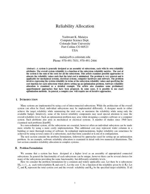
Software Reliability Measurements in N-Version Software Execution EnvironmentMichael R.LyuBellcoreInformation Sciences and Technologies Research Lab.Morristown,NJ07962(319)335-5957AbstractN-Version Programming has been proposed as a means to increasing software reliability by the attributes provided in fault tolerance.In this paper we will quantitatively examine the effective-ness of this approach.We look into the details of an academia/industry joint project employing six programming languages,and study the properties of the resulting program versions.We ex-plain how exhaustive testing was applied to the project,and measure the error probability in dif-ferent N-Version Software execution configurations.To explore the manifestations of errors resulting from each programming fault,and to study their impact to N-Version Software systems, we apply mutation testing techniques to gain more insights.We further define several reliability-related quantities,including error frequency function,error severity function,error similarity function,and safety coverage factor.With the multiple program versions obtained in the project,we create a total of93mutants,and measure the reliability quantities for each of them.Based on these quantities,we estimate the safety coverage factor for the N-Version Software system,which reveals the potential of this technique in improving software reliability.A side observation of this research is that the per fault error rate does not remain constant in this computation-intensive project.The error rates associated with each program fault differ from each other dramatically.However,they tend to decrease as testing progresses.This information might be helpful for practitioners to decide which models to apply for software reliability meas-urement in a similar project.Keywords:Software Failure Data,N-Version Programming,Mutation Testing,Software Relia-bility,Coverage Analysis.Software Reliability Measurements In N-Version Software Environment1.IntroductionThe N-Version Programming(NVP)approach to fault-tolerant software systems involves the generation of functionally equivalent,yet independently developed software components, called N-version software(NVS)[1].These components are executed concurrently under a supervisory system that uses a decision algorithm based on consensus to determinefinal output values[2].Whenever probability of similar errors is minimized,distinct,erroneous results tend to be masked by a majority vote during NVS execution[3].NVS systems are gaining acceptance in critical application areas such as the aerospace industry[4][5][6][7],nuclear power industry[8][9][10],and ground transportation industry[11] [12].However,the evaluations of such systems,especially in the context of reliability-related measures,are still left as a controversial issue.There are many conflicting observations about the effectiveness of this fault-tolerance technique in increasing software reliability[13][14].In this paper,we will revisit the program versions obtained in a six-language project,using Ada,C, Modula-2,Pascal,Prolog,and T(a lisp dialect)[15],and evaluate the reliability aspects of the resulting NVS executions from various angles.2.The Automatic Landing ProblemAn industrial investigation concerning the effectiveness of the NVP process was conducted in an academia/industry joint project utilizing an NVP design paradigm[16].The application was an automaticflight control function for the landing of commercial airliners that had been imple-mented by the Honeywell Incorporated to build a3-version Demonstrator System(hardware and software),employed to show the feasibility of N-version programming for this type of applica-tion.The specification could be used to develop the software of aflight control computer(FCC, or autopilot)for a real aircraft,given that it was adjusted to the performance parameters of a specific aircraft.All algorithms and control laws in the application were specified by diagramswhich had been certified by the Federal Aviation Administration (FAA).The pitch control part of the automatic landing problem,i.e.,the control of the vertical motion of the aircraft,was selected for the project.The major system functions of the pitch control and its data flow are shown in Figure 1.BAROMETRIC ALTITUDE COMP.FILTER RADIO ALTITUDE COMP.FILTER GLIDE SLOPE DEVIATION COMP.FILTER MODE LOGIC I I II ALTITUDE HOLD GLIDE SLOPE CAPTURE &TRACK FLARE I I I x y z LC COMMAND MONITORS (2) I CM DISPLAY D I x y z Legend:I =Airplane Sensor InputsLC =Lane CommandCM =Command Monitor OutputsD =Display OutputsFigure 1:Pitch Control System Functions and Data Flow DiagramIn this application,the autopilot is engaged in the flight control beginning with the initiali-zation of the system in the Altitude Hold mode,at a point approximately ten miles from the air-port.Initial altitude is about 1500feet,initial speed 120knots (200feet per second).Pitch modes entered by the autopilot/airplane combination,during the landing process,are:Altitude Hold (AHD),Glide Slope Capture (GSCD),Glide Slope Track (GSTD),Flare (FD),and Touchdown (TD).The Complementary Filters preprocess the raw data from the aircraft’s sensors.The Barometric Altitude and Radio Altitude Complementary Filters provide estimates of true altitude from various altitude-related signals,where the former provides the altitude reference for theAltitude Hold mode,and the latter provides the altitude reference for the Flare mode.The Glide Slope Deviation Complementary Filter provides estimates for beam error and radio altitude in the Glide Slope Capture and Track modes.Pitch mode entry and exit is determined by the Mode Logic equations,which usefiltered airplane sensor data to switch the controlling equations at the correct point in the trajectory.Each Control Law consists of two parts,the Outer Loop and the Inner Loop,where the Inner Loop is very similar for all three Control Laws.The Altitude Hold Control Law is responsible for maintaining the reference altitude,by responding to turbulence-induced errors in attitude and alti-tude with an automatic elevator command that controls the vertical motion.As soon as the edge of the glide slope beam is reached,the airplane enters the Glide Slope Capture and Track mode and begins a pitching motion to acquire and hold the beam center.A short time after capture,the track mode is engaged to reduce any static displacement towards zero.Controlled by the Glide Slope Capture and Track Control Law,the airplane maintains a constant speed along the glide slope beam.Flare logic equations determine the precise altitude(about50feet)at which the Flare mode is entered.In response to the Flare control law,the vehicle is forced along a path which tar-gets a vertical speed of two feet per second at touchdown.Each program checks itsfinal result(elevator command of each lane,or land command) against the results of the other programs.Any disagreement is indicated by the Command Moni-tor output,so that a supervisor program can take an appropriate action.The Display continuously shows information about the autopilot on various panels.The current pitch mode is displayed for the information of the pilots(Mode Display),while the results of the Command Monitors(Fault Display)and any one of sixteen possible signals(Signal Display)are displayed for use by the flight engineer.Upon entering the Touchdown mode,the automatic portion of the landing is complete and the system is automatically disengaged.This completes the automatic landingflight phase.In summary,this application could be classified as a computation-intensive,real-time system.3.The NVS Error Detection and Recovery AlgorithmsThe original software specifications specified test points ,i.e.,selected intermediate values of each major system function that had to be provided as outputs for additional error checking.Error detection was easily identified from the test points with some modifications.A further enhancement to the application was the introduction of seven cross-check points (ccp ’s)[1][17],and a recovery point [18].Error recovery could happen at each cross-check point,and at the recovery point before the result was fed back as input for the next computation.Cross-check points and recovery points were easily specified with their proper format and sequence.The usage of the ccp’s and recovery point in this application program is shown in Figure 2.Airplane SensorInput Generation sensor.input Lane Command Computation(lane.input)Command Monitors,Display ComputationIssuing Recovery?state.recovery RecoveryMechanismyesno Complementary Filters Processing ccp.filter1,ccp.filter2Mode Logic Processing ccp.modelogic Outer Loop Computation ccp.outerloop Inner Loop Computation ccp.innerloopCommand Monitors Computation ccp.monitors Display Computation ccp.display Figure 2:Usage of Cc-points and Recovery-point in the ApplicationIn Figure2,execution scenario of the application was designed to iterate through the fol-lowing computations:1)airplane sensor input generation;2)lane command computation;3) command monitors and display computation;and4)recovery mechanism when necessary.The airplane simulator was separated designed by a coordinating ne command,command monitors and display module were implemented by the programming teams.The recovery mechanism was provided in a supervisory environment[19][20].Under this scenario,the application software was instrumented by some fault tolerance mechanisms.Two input points(sensor.input,lane.input)were specified to receive external sen-sor input from an airplane,and to receiveflight commends from the other channels(lanes). Moreover,seven cross-check points(ccp.filter1,ccp.filter2,ccp.modelogic,ccp.outerloop, ccp.innerloop,ccp.monitors,ccp.display)were used to cross-check the results of the major sys-tem functions(Complementary Filters,Mode Logic,Outer Loop,Inner Loop,Command Moni-tors,Display)with the results of the other versions before they were used in any further computa-tion.Finally,One recovery point(state.recovery)was used to recover a failed version by supply-ing it with a set of new internal state variables that were obtained from the other versions by the Community Error Recovery technique[18].In summary,these fault tolerance mechanisms introduce14external variables(for input functions),68intermediate andfinal variables(for cross-check functions),and42state variables (for recovery function)in this application.State variables were identified as those variables whose values in the current iteration would affect their new values in the next iteration.Integra-tors,filters,and rate-limiters in the system denoted these variables.4.Software Testing ConductedTo emphasize the importance of testing,three phases of testing:unit tests,integration tests, and acceptance tests,were conducted.Different strategies for program testing were provided in order to clean up programs.Table1lists the differences among these phases.category unit test integration test acceptance testtest criteria structure-based requirements-based requirements-basedtest case open loop by closed loop by closed loop bygenerator PC Basic PC Basic multiple languagestest datafile i/o by each interfacing C interfacing Caccess version routines routinestested by individual teams individual teams coordinating teamtolerance0.01for degrees0.01for degrees0.005for degreeslevel(0.05for Prolog)#of test cases13349total executions133096018,440Table1:Different Schemes Used in the Testing PhasesThe unit test was considered as structure-based test since its test data was provided in such a way to facilitate programmers in hand-tracing the execution of their program units.The integra-tion test and acceptance test,on the other hand,utilized purely requirements-based test data.A reference model of the control laws was implemented and provided by Honeywell Inc.This ver-sion was implemented in Basic on an IBM PC to serve as the test case generator for unit tests and integration tests.Criteria of"open loop testing"and"closed loop testing"were used,respectively. Due to the wide numerical discrepancies between this version and the other six program versions under development,a larger tolerance level was chosen.Later in the acceptance test,this reference model proved to be less reliable(several faults were found)and less efficient.Thus,it was necessary to replace it with a more reliable and efficient testing procedure for a large volume of test data.For this procedure,the outputs of the six versions were voted and the majority results were used as the reference points to generate test data during the acceptance tests.This was also the test phase during which programmers were required to submit their programs to the coordinating team and wait for the test results.Afiner tolerance level was used based on the observation that less discrepancies were expected if pro-grams computed the right results.An exception had to be made for the Prolog program due tothe lack of accuracy in its internal representation of real numbers.In the unit test phase,each module of the program received a variant number of test cases.A total of133test cases were executed,and since each test case contained10program execu-tions,there were1330executions in this phase.Four testing profiles were provided for the integration test.Each test profile contained12 seconds offlight simulation,a total of960executions.These four test data sets differed from each other in theflying modes that were involved(either Altitude Hold Mode only,or from Alti-tude Hold Mode to Glide Slope Capture and Track Modes),and by the level of wind turbulence (either no wind turbulence or an average wind turbulence)being superimposed.The acceptance test was a stringent testing phase.Nine testing profiles were designed for this test phase.Data sets1,3,and5executed for100seconds,driving the airplane from Altitude Mode to Glide Slope Capture and Track Modes with different magnitude of wind turbulences. Data sets2,4,and6were designed similarly,except they exercised allfiveflying modes for180 seconds.Data sets7and8were designed to carry out the recovery command,and Data set9the Display module.The total executions required in this phase were18440program iterations.5.Software Metrics and Fault Distributions of the ProgramsTable2gives several comparisons of the six versions with respect to some common software metrics.The objective of software metrics is to evaluate the quality of the product in a quality assurance environment.However,our focus here is the comparison among the program versions,since design diversity is our major concern.The following metrics are considered in Table2:(1)the number of lines of code,including comments and blank lines(LINES);(2)the number of lines excluding comments and blank lines (LN-CM);(3)the number of executable statements,such as assignment,control,I/O,or arith-metic statements(STMTS);(4)the number of programming modules(subroutines,functions, procedures,etc.)used(MODS);(5)the mean number of statements per module(STM/M);(6)the mean number of statements in between cross-check points(STM/CCP);(7)the number of calls toprogramming modules(CALLS);(8)the number of global variables(GBVAR);(9)the number of local variables(LCVAR);and(10)the number of binary decisions(BINDE).Metrics ADA C MOD-2PASCAL PROLOG T RangeLINES225313781521223417331575 1.64:1LN-CM1517861953128813741263 1.76:1STMTS103174654649112571089 2.56:1MODS362637487744 2.96:1STM/M292515101625 2.90:1STM/CCP1471077870179156 2.56:1CALLS976865938187 1.49:1GBVAR13914191819097 1.74:1LCVAR117197132127209251 2.15:1BINDE74114781187486 1.59:1Table2:Software Metrics for the Six ProgramsA total of93faults was found and reported during the whole life cycle of the project.Table 3shows the test phases during which the faults were detected,and the fault densities(as per thousands of executable statements)of the original version and the accepted version.It also shows test efficiency for fault removal during software development,defined as the number of faults found prior to operational testing divided by the number of total faults.Test Phase ADA C MOD-2PASCAL PROLOG T TotalCoding/Unit Testing2441015742Integration Testing25027420Acceptance Testing240041020Operational Testing05103211Total618512292393Original Fault Density 5.824.29.224.423.121.118.0Test Efficiency100%72%80%100%90%91%88%Operational Fault Density0.0 6.7 1.80.0 2.4 1.8 2.1Table3:Fault Classification by Phases and Other AttributesIt is interesting to note that there was only one incidence of an identical fault,committed by two teams,Ada and Modula-2,during program development phase.This fault was due to a comma being misread as a period,which was classified as a specification misinterpretation.Dur-ing operational testing,two disagreements were traced to an identical fault occurred in the Prolog and T versions,which was due to the programmers’ignorance to properly incorporate a late specification update.Both pairs of identical faults were related to specification.However,ident-ical faults involving more than two versions have never been observed.6.N-Version Software System Executions and ResultsThe operational testing of the project was a dynamic,requirements-based testing stressing how the airplane/autopilot interacted and operated in an actual environment.Three channels of diverse software each computed a surface command to guide a simulated aircraft along itsflight path.To ensure that significant command errors could be detected,random wind turbulences of different levels were superimposed in order to represent difficultflight conditions.The indivi-dual commands were recorded and compared for discrepancies that could indicate the presence of faults.The configuration of theflight simulation system(shown in Figure3)was consist of three lanes of control law computation,three command monitors,a servo control,an Airplane model, and a turbulence generator.LANE A COMPUTATION LANE B COMPUTATION LANE C COMPUTATION COMMAND MONITOR ACOMMAND MONITOR B COMMANDMONITOR C SERVO-CONTROL /SERVOSAIRPLANE /SENSORS /LANDING GEOMETRY TURBULENCEGENERATOR Figure 3:3-Channel Flight Simulation ConfigurationThe lane computations and the command monitors were the redundant software versions generated by the six programming teams.Each lane of independent computation monitored the other two lanes.However,no single lane could make the decision as to whether another lane was faulty.A separate servo control logic function was required to make that decision,based on the monitor states provided by all the lanes.This control logic applied a strategy that ignored the elevator command from a lane when that lane was judged failed by both of the other two lanes,given that these two lanes were judged valid.The aircraft mathematical model provided the dynamic response of current medium size,commercial transports in the approach/landing flight phase.In this model,the airplane was trimmed,by means of flaps and engine thrust setting,to a landing speed of about 120knots,and a level of low altitude flight path was chosen.It was assumed that the pilot has engaged the autothrottle while in the low-speed,approach condition,so that forward speed variations werenegligible.In addition,the pilot was assumed to have maneuvered the aircraft to an altitude of 1500feet in preparation for engagement of the Altitude Hold mode.The three control signals from the autopilot computation lanes were inputs to three elevator servos.The servos were force-summed at their outputs,so that the mid-value of the three inputs became thefinal elevator command.Sensed airplane attitude,attitude rate,altitude,flight path,and vertical acceleration motions were directly measured by various sensors mounted in the fuselage,which were properly modeled.It was assumed that these sensors were at the center-of-gravity of the aircraft,and had unity gain characteristics.The reaction of the airplane(e.g.,the pitch attitude)should be able to stablize the path of theflight in responding tofluctuating inputs.Landing Geometry and Turbulence Generator were models associated with the Airplane simulator.The Landing Geometry mathematical model described the deviation from glideslope beam center as a function of aircraft position relative to the end of the runway.Nominal glideslope beam characteristics were defined by a beam angle of2.5degrees referenced to the touchdown point,and a width in the vertical plane of±0.5degrees around the beam center. Interception of the lower edge of the beam by the aircraft resulted in a pitch-over command and acquisition of the beam center.The Turbulence Generator model was used to introduce vertical wind gusts.Vertical turbulence was assumed to be frozen with respect to time.This was based on the observation that for reasonableflight speeds,changes in vertical wind velocity were smaller with respect to time than with respect to position.In summary,one run offlight simulation was characterized by the followingfive initial values:(1)initial altitude(about1500feet);(2)initial distance(about52800feet);(3)initial nose up relative to velocity(range from0to10degrees);(4)initial pitch attitude(range from-15to15 degrees);and(5)vertical velocity for the wind turbulence(0to10ft/sec).One simulation con-sisted of about5000iterations of lane command computations(50milliseconds each)for a total landing time of approximately250seconds.In this manner,over1000flight simulations(over 5,000,000program executions)were exercised on the six software versions generated from thisproject.Table4shows the errors encountered in each single version,while Table5shows different error categories under all combinations of3-version and5-version configurations.Note that the discrepancies encountered in the operational testing were called"errors"rather than"failures"due to their non-criticality in the landing procedure,i.e.,a proper touchdown was still achieved.size total number of errorversion(l.o.c.)executions errors probabilityAda225651274000.0000000C15315127400568.0001108Modula-2156251274000.0000000Pascal233151274000.0000000Prolog22285127400680.0001326T15685127400680.0001326Average19135127400321.00006267Table4:Errors in Individual Versions3-version configuration5-version configurationcate-gory#of cases probability#of cases probability1.102531685.999840930757655.99978072.13385.00013055890.00019153.210.00000204870.0000022754.2720.00002652680.000022105.--105.000003413Total102548000 1.000000030764400 1.0000000classifications of the category:1-no errors2-single errors in one version3-two distince errors in multiple versions4-two coincident errors in multiple versions5-three errors in multiple versionsTable5:Errors in3-Version and5-Version Execution Configurations From Table4we can see that the average error probability for single version is.00006267.Table5shows that for all the3-version combinations,the error probability concerning reliability is.00002857(categories3and4),and that for safety is.00002652(category4).This is a reduc-tion of roughly2.3.In all the combinations of5-version configuration,the error probability for reliability is.000003413(category5;Two of the three errors are coincident,resulting in no-decision),a reduction by a factor of18.This probability becomes zero in the safety measure-ment.From these numbers it might be interpreted that the expected dependability improvement of NVS over single-version software is quite moderate.However,it is noted that the coincident errors produced by the Prolog and T programs were all caused by one identical fault in both ver-sions,which was due to the ignorance of a slight specification update that was made very late in the programming process.This fault manifested itself right after these program versions were put together for theflight simulation.Had this fault been eliminated in the operational testing, categories3,4and5for both3-version and5-version configurations in Table5would have been all zero,resulting in perfect dependabilityfigures.7.Fault Diagnosis and Error Analysis by Mutation TestingTo uncover the impact of faults that would have remained in the software version,and to evaluate the effectiveness of NVS mechanisms,a special type of regression testing,similar to mutation testing which is well known in the software testing literature[21][22],was investigated in the six versions.The original purpose of the mutation testing is to ensure the quality of the test data used to verify a program,while our concern here was to examine the relationship of faults and error frequencies in each program and to evaluate the similarity of program errors among dif-ferent versions.The testing procedure is described in the following steps:1)The fault removal history of each program was examined and each program fault was analyzed and recreated.2) Mutants were generated by injecting faults one by one into thefinal version from where they were removed(i.e.,a fault from the C program will be injected to the C program only).Each mutant contains exactly one known software fault.3)Each mutant was executed by the same setof input data in the Airplane simulation environment to observe errors.4)Analyze the error characteristics to collect error statistics and correlations.Using the fault removal history of each version,we created 6mutants for Ada (a1-a6),18mutants for C (c1-c18),5mutants for Modula-2(m1-m5),12mutants for Pascal (p1-p12),29mutants for Prolog (pg1-pg29),and 23mutants for T (t1-t23).A higher index number in each mutant represents the injection of a later fault to that version.In order to present the execution results of the above procedure,let us define the following two functions for each mutant:Error Frequency Function (for a given set of test data)−the frequency of the error beingtriggered by the specified test data set in this mutant.Error Severity Function (for a given set of test data)−the severity of the error when mani-fested in the system by the specified test data set.An Error Frequency Function of version x mutant i for test set τ,denoted as λ(x i ,τ),is computed byλ(x i ,τ)=total number of executionstotal number of errors when executing test set τon mutant x i Since each mutant contains only one known fault,it is hypothesized that errors produced by that fault are always the same for the same test inputs[23].This hypothesis is considered valid for all the mutants discussed here.Therefore,we can define an Error Severity Function of version x mutant i for test set τ,µ(x i ,τ),to beµ(x i ,τ)= 1ref erence value ref erence value −error of x i 0,otherwise ,if ε< ref erence value ref erence value −error of x i <1,if 0< ref erence value ref erence value −error of x i <εwhere εis a specified allowed deviation.If x i produces run-time exceptions or no results,thenµ(x i,τ)is defined to be1.The Error Frequency Function and Error Severity Function applied to each mutant(for a test set of about15000executions)are shown in Table6and Table7,respectively.Id ADA C MOD-2PASCAL PROLOG T10.00021010120.0010.00370.00100.00061310.50.005011410.000100.00011150.00010.0037010.00051600−0.002107−0.001−0.001118−0−0.0010.119−0−0.00010.0005110−0−010.511−0.0005−0.0011112−0−0.00021013−0−−1014−0−−0.0001015−0.03−−10.00216−0−−1017−0−−10.002818−0−−0019−−−−1020−−−−1021−−−−1022−−−−10.00123−−−−0.0001024−−−−0−25−−−−0.0001−26−−−−0−27−−−−0.001−28−−−−0−29−−−−0−"−"means the mutant for that version does not exist.Table6:Error Frequency Function of Each Mutant。