厚声贴片电阻规格中文版
- 格式:pdf
- 大小:968.37 KB
- 文档页数:3
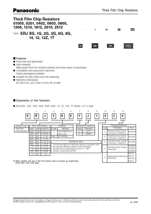
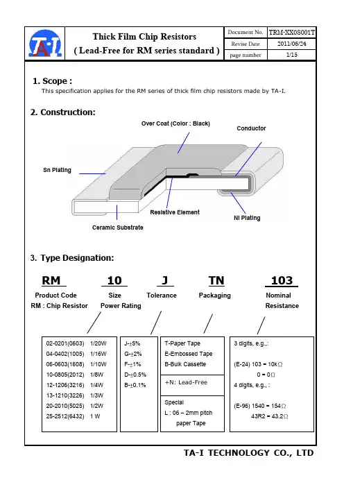
ContentsIntroduction ………………………………………………………………………………………Page1.0 Scope (4)2.0 Ratings & Dimension ………………………………………………………….…………....4~53.0 Structure.................................... (5)4.0 Marking…….…………………………………… ………………………. ..… …………… 6~75.0 Derating Curve................................................... .. (8)6.0 Performance Specification …………………………………………….……………..........8~97.0 Explanation of Part No. System ………………………………….…………………………9~108.0 Ordering Procedure (10)9.0 Standard Packing ………………………………………………….…………………………11~1210.0 Note Matter.................................................................. . (12)File Name:CHIP SERIES±0.5%,±1%,±2%,±5%& 0ΩDate 2013.12.20EditionNo. 1Amendment Record Signature Edition Prescription of amendment Amend Page Amend Date Amended by Checked by1.0 Scope:This specification for approve relates to the Lead-Free Thick Film Chip Resistors manufactured byROYALOHM.2.0 Ratings & Dimension:01005、0201、04020603、0805、1206、1210、1812、2010、25122.1 Dimension & Resistance Range :Type70℃ PowerDimension(mm) Resistance RangeL W H A B 0.5% 1.0% 2.0% 5.0%01005 1/32W 0.40±0.02 0.20±0.02 0.13±0.02 0.10±0.050.10±0.03--10Ω-10M Ω 10Ω-10M Ω10Ω-10M Ω0201 1/20W 0.60±0.03 0.30±0.03 0.23±0.03 0.10±0.050.15±0.05-- 1Ω-10M Ω 1Ω-10M Ω1Ω-10M Ω0402 1/16W 1.00±0.100.50±0.05 0.35±0.05 0.20±0.100.25±0.101Ω-10M Ω0.2Ω~22M Ω 0.2Ω~22M Ω0.2Ω~22M Ω06031/16W 1/10WS 1.60±0.10 0.80±0.10 0.45±0.10 0.30±0.200.30±0.201Ω-10M Ω0.1Ω~33M Ω 0.1Ω~33M Ω0.1Ω~100M Ω0805 1/10W 1/8WS 2.00±0.15 +0.151.25-0.10 0.55±0.10 0.40±0.200.40±0.201Ω-10M Ω0.1Ω~33M Ω 0.1Ω~33M Ω0.1Ω~100M Ω1206 1/8W 1/4WS 3.10±0.15 +0.151.55-0.100.55±0.10 0.45±0.200.45±0.201Ω-10M Ω0.1Ω~33M Ω 0.1Ω~33M Ω0.1Ω~100M Ω1210 1/4W1/3WS 1/2WSS3.10±0.10 2.60±0.20 0.55±0.10 0.50±0.250.50±0.201Ω-10M Ω0.1Ω~10M Ω 0.1Ω~22M Ω0.1Ω~100M Ω18121/2W 3/4WS 4.50±0.20 3.20±0.20 0.55±0.20 0.50±0.200.50±0.200.1Ω-10M Ω0.1Ω-10M Ω 0.1Ω-10M Ω0.1Ω-10M Ω2010 1/2W 3/4WS5.00±0.10 2.50±0.20 0.55±0.10 0.60±0.250.50±0.201Ω-10M Ω0.1Ω~22M Ω 0.1Ω~22M Ω0.1Ω~22M Ω2512 1W 6.35±0.10 3.20±0.20 0.55±0.10 0.60±0.250.50±0.201Ω-10M Ω0.1Ω~33M Ω 0.1Ω~33M Ω0.1Ω~33M Ω2.2 RatingsType70℃PowerMax 。
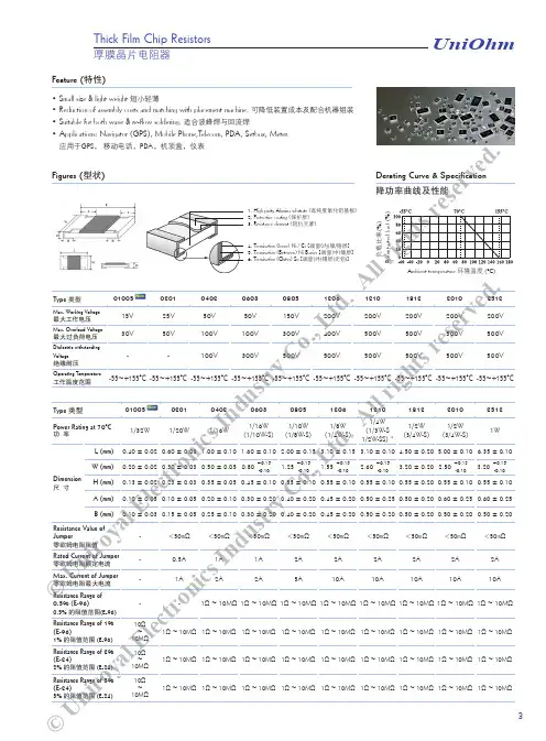
• Small size & light weight 短小轻薄• Reduction of assembly costs and matching with placement machine. 可降低装置成本及配合机器组装• Suitable for both wave & re-flow soldering. 适合波峰焊与回流焊• Applications: Navigator (GPS), Mobile Phone,Telecom, PDA, Setbox, Meter. 应用于GPS , 移动电话,PDA ,机顶盒,仪表Feature (特性)Figures (型状)Derating Curve & Specification降功率曲线及性能Thick Film Chip ResistorsP e r c e n t r a t e d l o a d (%)Ambient termperature 环境温度 (°C)厚膜晶片电阻器负载比率(%)UniOhm3r i g h s e rv ed .©UValue阻值Code 代码Value 阻值Code 代码Value 阻值Code 代码Value 阻值Code 代码Value 阻值Code 代码Value 阻值Code 代码100011471721533316494646568181102021501822134324504756669882105031541922635332514876771583107041582023236340524996873284110051622123737348535116975085113061652224338357545237076886115071692324939365555367178787118081742425540374565497280688121091782526141383575627382589124101822626742392585767484590127111872727443402595907586691130121912828044412606047688792133131962928745422616197790993137142003029446432626347893194140152053130147442636497995395143162103230948453646658097696Thick Film Chip Resistors• For 0201 & 0402 size, no marking on the body due to the small size of the resistor. 0201, 0402因电阻本体太小,故本体无标示字码• ±5% tolerance product: the marking is 3 digits, the first 2 digits are the significant of theresistance and the 3rd digit denotes number of zeros following.±5%公差产品字码是三位数,前二位是阻值的有效数,第三位表示有几个 0• 0805, 1206, 1210, 2010, 2512 ≤±1%: the marking is 4 digits, the first 3 digits are the significant of the resistance and the 4th digit denotes number of zeros following. 0805, 1206, 1210, 2010, 2512 ≤±1%公差产品字码有四位数,前三位是阻值的有效数,第四位表示有几个 0Marking on the Resistors Body (电阻本体字码标示)2372 = 23700Ω = 23.7KΩBelow 10Ω : 3R24 = 3.24Ω10Ω 以下标示: 3R24 = 3.24Ω153 = 15000Ω = 15KΩBelow 10Ω: 6R8 = 6.8Ω10Ω 以下标示: 6R8 = 6.8Ω• Standard E-96 series values of 0603 ≤±1%: due to the small size of the resistor’s body, 3 digits marking will be used to indicate the accurate resistance value by using the following Multiplier & Resistance Code.0603 ≤±1%公差 E-96系列标准阻值,因电阻本体太小,采用三位阻值代码(数字)及下列指数代码(字母)配合来指明标准的阻值。
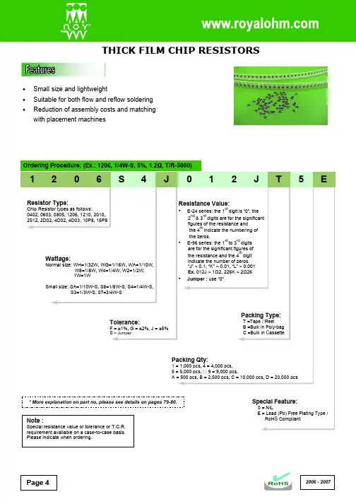
Page 4•Small size and lightweight• Suitable for both flow and reflow soldering•Reduction of assembly costs and matching with placement machines2006 - 20072006 - 2007 Page 52006 - 2007Marking on the Resistors Body:• For 0402 size, no marking on the body due to the small size of the resistor.•±5% tolerance product. (Including resistance values less than 1Ω; both 1% and 5%) The marking is 3 digits, the first 2 digits are the significant figures of the resistance and the 3rd digit denotes number of zeros.153 = 15000Ω = 15K Ω; 120 = 12ΩBelow 10Ω shown as this: 6R8 = 6.8Ω• 1% tolerance marking of case size 0805 and bigger is 4 digits, the first 3 digits are the significant figures of the resistance and the 4th digit denotes number of zeros.2372 = 23700Ω = 23.7K Ω; 1430 = 143Ω Below 10Ω shown as this: 3R24 = 3.24ΩPage 6* More details, please see pages 77-78.• Standard E-96 series values (±1% tolerance) of 0603 size. Due to the small size of the resistor’s body, 3 digitsmarking will be used to indicate the accurate resistance value by using the Multiplier code & Standard E-96 Series Resistance Value Code as shown on Page 6.1.96K Ω = 196 x 101 Ω = 29B12.4Ω = 124 x 10-1 Ω = 10X• Standard E-24 series values which does not belong to E-96 series values (±1% tolerance) of 0603 size. The marking is the same as 5% tolerance but mark with underline.122 = 1200 = 1.2K Ω 680 = 68ΩTemperature coefficient ±5%: 1Ω ~ 10M Ω ≤ ±200PPM/°C±1%: 10Ω ~ 100Ω ≤ ±200PPM/°C; 101Ω ~ 1M Ω ≤ ±100PPM/°CShort-time overload ±5%: ±(2.0% + 0.1Ω) Max.±1%: ±(1.0% + 0.1Ω) Max.Insulation resistanceMin. 1,000 Mega OhmDielectric withstanding voltageNo evidence of flashover, mechanical damage, arcing or insulation breakdown Terminal bending±(1.0% + 0.05Ω) Max.Soldering heat ±(1.0% + 0.05Ω) Max.SolderabilityMin. 95% coverage Temperature cycling±5%: ±(1.0% + 0.05Ω) Max.±1%: ±(0.5% + 0.05Ω) Max.Humidity (Steady s tate) ±5%: ±(3.0% + 0.1Ω) Max.±1%: ±(0.5% + 0.1Ω) Max.Load life in humidity±5%: ±(3.0% + 0.1Ω) Max.±1%: ±(1.0% + 0.1Ω) Max.Load life±5%: ±(3.0% + 0.1Ω) Max.±1%: ±(1.0% + 0.1Ω) Max.* The values which are not of standard E-24 series (2% & 5%) and not of E-96 series (1%) could be offered on a case to case basis.2006 - 2007Page 7。
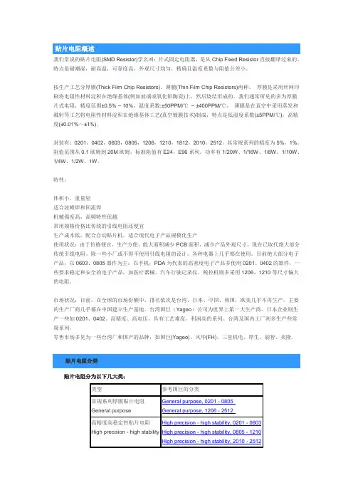
我们常说的贴片电阻(SMD Resistor)学名叫:片式固定电阻器,是从Chip Fixed Resistor直接翻译过来的。
特点是耐潮湿,耐高温,可靠度高,外观尺寸均匀,精确且温度系数与阻值公差小。
按生产工艺分厚膜(Thick Film Chip Resistors)、薄膜(Thin Film Chip Resistors)两种。
厚膜是采用丝网印刷将电阻性材料淀积在绝缘基体(例如玻璃或氧化铝陶瓷)上,然后烧结形成的。
我们通常所见的多为厚膜片式电阻,精度范围±0.5% ~ 10%,温度系数:±50PPM/℃~ ±400PPM/℃。
薄膜是在真空中采用蒸发和溅射等工艺将电阻性材料淀积在绝缘基体工艺(真空镀膜技术)制成,特点是低温度系数(±5PPM/℃),高精度(±0.01%~±1%)。
封装有:0201,0402,0603,0805,1206,1210,1812,2010,2512。
其常规系列的精度为5%,1%。
阻值范围从0.1欧姆到20M欧姆。
标准阻值有E24,E96系列。
功率有1/20W、1/16W、1/8W、1/10W、1/4W、1/2W、1W。
特性:体积小,重量轻适合波峰焊和回流焊机械强度高,高频特性优越常用规格价格比传统的引线电阻还便宜生产成本低,配合自动贴片机,适合现代电子产品规模化生产使用状况:由于价格便宜,生产方便,能大面积减少PCB面积,减少产品外观尺寸,现在已取代绝大部分传统引线电阻。
除一些小厂或不得不使用引线电阻的设计,各种电器上几乎都在使用。
目前绝大部分电子产品,以0603、0805器件为主;以手机,PDA为代表的高密度电子产品多使用0201、0402的器件;一些要求稳定和安全的电子产品,如医疗器械、汽车行驶记录仪、税控机则多采用1206、1210等尺寸偏大的电阻。
市场状况:目前,在全球的市场份额中,排名依次是台湾、日本、中国、韩国,欧美几乎不再生产。
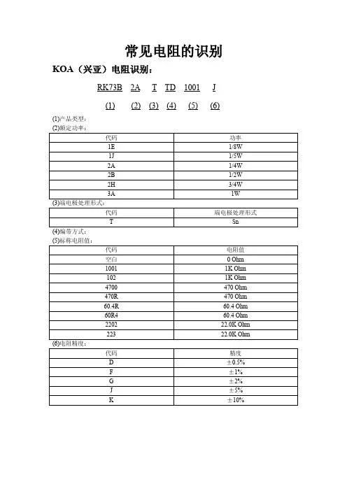
常见电阻的识别KOA(兴亚)电阻识别:RK73B2A T TD1001J(1)(2)(3)(4)(5)(6)(1)产品类型:(2)额定功率:代码功率1E1/8W1J1/5W2A1/4W2B1/2W2H3/4W3A1W (3)端电极处理形式:代码端电极处理形式T Sn(4)编带方式:(5)标称电阻值:代码电阻值空白0Ohm10011K Ohm1021K Ohm4700470Ohm470R470Ohm60.4R60.4Ohm60R460.4Ohm220222.0K Ohm22322.0K Ohm (6)电阻精度:代码精度D±0.5%F±1%G±2%J±5%K±10%ROHM(罗姆)电阻识别:MCR01MZP J102(1)(2)(3)(4)(5)(1)电阻类型:代码类型MCR厚膜电阻器PMR金属盘电阻器ESR抗波动型厚膜电阻器KTR耐高压厚膜电阻器MNR网络型厚膜电阻器RCN贴片式衰减型厚膜电阻器MVR贴片式微条型厚膜电阻器(2)封装尺寸、功率及耐压:代码型号英制长×宽功率耐压00602010.6×0.3mm1/20W25V 010402 1.0×0.5mm1/16W50V 030603 1.6×0.8mm1/10W50V 100805 2.0×1.25mm1/8W150V (3)元件个数:代码个数JZH4000EZH5000HZP2000EZP5000MZP10000YZP15000EOAP5000MOAP10000HXBR2000IXBR3000KXBR5000(4)电阻精度:代码精度D±0.5%F±1%G±2%J±5%K±10%(5)标称电阻值:代码电阻值0000Ohm1021K Ohm UNIOHM(厚声)电阻识别:1206S4J012J T5E(1)(2)(3)(4)(5)(6)(7)(1)封装尺寸:型号公制型号英制长×宽050302010.5×0.25mm10050402 1.0×0.5mm16080603 1.5×0.76mm20120805 2.0×1.25mm32161206 3.2×1.6mm32251210 3.2×2.5mm45321812 4.5×3.2mm (2)额定功率:代码功率WM1/20WWG1/16WWA1/10WW81/8WW41/4WW21/2W073/4W1W1W1A1/10WSS81/8WSS41/4W-SU21/2WSSS21/2W-S073/4W-S(3)电阻精度:代码精度D±0.5%F±1%G±2%J±5%(4)标称电阻值:代码电阻值100210K Ohm10011K Ohm00000Ohm012J 1.2Ohm012K0.12Ohm012L0.012Ohm注:前三位表示有效数字,后一位表示有几个0,其中J=0.1,K=0.01,L=0.001。
贴片电阻对应尺寸表贴片电阻是一种常见的电子元器件,广泛应用于各种电子设备中。
在选择适合的贴片电阻时,我们需要参考贴片电阻对应尺寸表,以确保选取的电阻尺寸符合设计要求。
一、贴片电阻的尺寸参数贴片电阻的尺寸通常由长度、宽度和厚度三个参数来描述。
以毫米为单位,常见的尺寸范围如下:1. 长度(L):从0.5mm到7.0mm不等。
2. 宽度(W):从0.125mm到5.0mm不等。
3. 厚度(T):从0.2mm到1.5mm不等。
根据实际需求,我们可以根据贴片电阻对应尺寸表来选择合适的尺寸。
二、贴片电阻尺寸的选择1. 小尺寸电路板:对于小尺寸的电路板,为了节省空间,我们可以选择较小尺寸的贴片电阻。
例如,长度为1.0mm、宽度为0.5mm、厚度为0.2mm的贴片电阻,可以满足空间限制的要求。
2. 大功率负载:对于需要承受较大功率负载的电路,我们需要选择具有较大尺寸的贴片电阻,以确保其能够承受高功率的工作条件。
例如,长度为5.0mm、宽度为3.2mm、厚度为1.5mm的贴片电阻,具有较高的功率承受能力。
3. 精密测量电路:对于需要高精度测量的电路,我们需要选择具有较小尺寸和较高稳定性的贴片电阻。
例如,长度为0.5mm、宽度为0.125mm、厚度为0.2mm的贴片电阻,具有较小的尺寸和较高的稳定性。
三、贴片电阻的尺寸与功率的关系贴片电阻的尺寸与其能够承受的功率有一定的关系。
一般来说,尺寸越大的贴片电阻,其功率承受能力也越大。
因此,在选择贴片电阻时,我们需要根据实际功率需求来确定合适的尺寸。
四、贴片电阻的尺寸对焊接工艺的影响贴片电阻的尺寸也会对焊接工艺产生影响。
较小尺寸的贴片电阻在焊接时需要更高的精度和技术要求,以确保焊接的质量。
而较大尺寸的贴片电阻则相对容易焊接。
五、贴片电阻尺寸的标准化为了方便选择和应用,贴片电阻的尺寸已经得到了标准化。
根据不同的国际标准,贴片电阻的尺寸参数可能会有所差异。
因此,在选择贴片电阻时,我们需要参考相应的标准,以确保选取的贴片电阻符合国际规范。

UniOhm Uniroyal Electronics Industry Co., Ltd.厚声电子工业有限公司88 LongTeng Road, Economic & Technical Development Zone,Kunshan City, Jiangsu, China中国江苏省昆山市经济技术开发区龙腾路88号邮编: 215301Tel: +86 512 5763 1400 / 1411 /1422 /1433Fax: +86 512 5763 4599*******************************************Contents目录Metal Strip Current Sensing Chip Resistors - MS 金属带电流检测片式电阻器22MS06, MS07, MS10, MS11, MS12, MS17, MS20, MS27Anti-Electro Static Discharge Thick Film Chip Resistors - ES 抗静电膜晶片电阻器24ES01, ES02, ES03, ES05, ES06, ES07Low T.C.R Thick Film Chip Resistors - LT 低温度系数厚膜晶片电阻器26LT02, LT03, LT05, LT06AEC-Q200 Version Chip Resistors - HQ 汽车用晶片电阻器28HQ02, HQ03, HQ05, HQ06, HQ07, HQ10 , HQ12Thick Film Chip Resistors Network 厚膜晶片网络电阻器4610P8, 10S8, 10T8, 10E9Packing of Surface Mount Resistors 表面贴装式电阻器包装47Packing of Surface Mount ResistorsResistor Network - SIP Series 网络电阻器 - SIP 系列48RNL-A, RNL-B, RNL-C, RNL-D, RNL-E, RNL-L, RNL-R,RNL-G, RNL-PHigh Power Resistor Network - SIP RPL Series 高功率网络电阻器- SIP RPL 系列50RPL-A, RPL-B, RPL-RHigh Power Resistors Network Medium Profile–SIP RNM Series高功率中宽度网络电阻器 - SIP RNM 系列52RNM-A, RNM-B, RNM-RHigh Power Resistors Network High Profile–SIP RPH Series高功率高宽度网络电阻器 - SIP RPH 系列54RPH-A, RPH-B, RPH-RSpecial Network –SIP Series 特殊网络电阻器 - SIP 系列56SN0001, SN0002, SN0003, SN0004Resistor/Capacitor Network-SIP Series 网络阻容器电阻器 - SIP 系列57RCN-A, RCN-BCapacitor Network-SIP Series 网络电容器 - SIP 系列58CNM-1High Voltage Flat Resistors 高压扁平式电阻器59HFRCarbon Film Fixed Resistors 碳膜电阻器60CFRPrecision Metal Film Fixed Resistors 精密金属膜电阻器62MFRCarbon Film Power Resistors 高功率碳膜电阻器64CPR Metal Film Power Resistors 高功率金属膜电阻器65MPRWire-wound Fusible Resistors 绕线保险丝型电阻器74KFRThermal Fusing Wire-wound Fixed Resistors 绕线型温度保险丝电阻器76TFRCurrent Sense Resistors 电流检测线电阻器77CSRCurrent Sense Spring Resistors 弹簧式电流检测电阻器78CSSA, CSSB, CSSCThrough Hole Category - Network Resistors & Traditional Coated Resistors (插件式 - 排列电阻 & 涂装型电阻)New New New New UniOhm1Contents目录Axial Leaded Terminal Type-PRW Series 轴式导线型 - PRW 系列 97PRW , PRWA, PRWCRadial Leaded T ype-PRM & PRS Series 立式导线型 - PRM & PRS 系列 98PRM, PRMA, PRMB, PRMT , PRSUltra-Low Value Cement Resistors 超低阻水泥固定电阻器108PRWUPower Flat Alloy Resistors 功率型合金箔电阻器109PFAS, PFATColumnar Type Cement Fixed Resistors 圆柱状水泥电阻器111QHOStandard Packing of Cement Type Resistors 水泥型电阻器包装标准112Bulk/BoxPower Dissipation Mount Resistors 铝外壳电阻器115PDMHigh-Power Wire-wound Resistors 高功率绕线型固定电阻器116BTRVitreous Enameled Wire-wound Resistors 珐琅釉绕线固定电阻器127URXPower Type Thermal Fusing Resistors 功率型温度保险丝电阻128TFO, TFRCPower (Ribbon) Wire-wound Resistors 功率(合金带)绕线型电阻器129QH, QL, QR, QRZGTest Method of JIS-C-5201 & JIS-C-5202JIS-C-5201和 JIS-C-5202 检测方法131Standard Nominal Resistance Value 标准电阻值133Explnation of Part No. System 料号系统注释135Standard Color Code System 标准色码系统137Metal Glaze Film Fixed Resistors 金属玻璃釉膜固定电阻器79MGRHigh-Value Metal Glaze Film Fixed Resistors 超高阻玻璃釉膜固定电阻器81HMGRHigh-Voltage Metal Glaze Film Fixed Resistors 耐高压型玻璃釉膜固定电阻器82HVRTerminal Type Metal Oxide Film Resistors 端片型金属氧化膜电阻器83TMOR, TMOV , TMOLJumper Wires & Zero-Ohm Resistors 跳线及零欧姆电阻器84ZW , ZO, ZFCopper Plated Steel Lead Wire Type & Cutting Type 铜包钢导线型及切割半成品型85CP, CO Panasert Type (Panasert 型)86Avisert Type (Avisert 型)87AVI-1, AVI-2, AVI-3M & F Forming Type (M 型 & F 型 <成型> )89MF , MK, ML, F , F1, F2, F3Standard Packing of Coated Type Resistors 涂装型电阻器包装标准91Tape/Box, Tape/Reel, Bulk/BoxThrough Hole Category - Traditional Cement Resistors (插件式 - 水泥型电阻)Power Type Resistors (功率型)RELATIVE INFORMATION (相关资料)UniOhm2• Small size & light weight 短小轻薄• Reduction of assembly costs and matching with placement machine. 可降低装置成本及配合机器组装• Suitable for both wave & re-flow soldering. 适合波峰焊与回流焊• Applications: Navigator (GPS), Mobile Phone,Telecom, PDA, Setbox, Meter.应用于GPS, 移动电话,PDA,机顶盒,仪表Feature (特性)Figures (型状)Derating Curve & Specification降功率曲线及性能Thick Film Chip ResistorsPercentratedload(%)Ambient termperature 环境温度 (°C)厚膜晶片电阻器负载比率(%)UniOhm3 RoHS CompliantValue阻值Code 代码Value 阻值Code 代码Value 阻值Code 代码Value 阻值Code 代码Value 阻值Code 代码Value 阻值Code 代码100011471721533316494646568181102021501822134324504756669882105031541922635332514876771583107041582023236340524996873284110051622123737348535116975085113061652224338357545237076886115071692324939365555367178787118081742425540374565497280688121091782526141383575627382589124101822626742392585767484590127111872727443402595907586691130121912828044412606047688792133131962928745422616197790993137142003029446432626347893194140152053130147442636497995395143162103230948453646658097696Thick Film Chip Resistors• For 01005, 0201, 0402 size, no marking on the body due to the small size of the resistor. 01005, 0201, 0402因电阻本体太小,故本体无标示字码• ±5% tolerance product: the marking is 3 digits, the first 2 digits are the significant of theresistance and the 3rd digit denotes number of zeros following.±5%公差产品字码是三位数,前二位是阻值的有效数,第三位表示有几个 0• 0805, 1206, 1210, 2010, 2512 ≤±1%: the marking is 4 digits, the first 3 digits are the significant of the resistance and the 4th digit denotes number of zeros following. 0805, 1206, 1210, 2010, 2512 ≤±1%公差产品字码有四位数,前三位是阻值的有效数,第四位表示有几个 0Marking on the Resistors Body (电阻本体字码标示)2372 = 23700Ω = 23.7KΩBelow 10Ω : 3R24 = 3.24Ω10Ω 以下标示: 3R24 = 3.24Ω153 = 15000Ω = 15KΩBelow 10Ω: 6R8 = 6.8Ω10Ω 以下标示: 6R8 = 6.8Ω• Standard E-96 series values of 0603 ≤±1%: due to the small size of the resistor’s body, 3 digits marking will be used to indicate the accurate resistance value by using the following Multiplier & Resistance Code. 0603 ≤±1%公差 E-96系列标准阻值,因电阻本体太小,采用三位阻值代码(数字)及下列指数代码(字母)配合来指明标准的阻值。
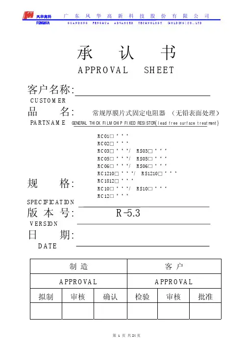
Approval SheetforThick Film Chip ResistorRL series1% 2% 5%YAGEO CORPORATIONFactory: No.11, Min Chuan Rd., Ta Sheh, Kaohsiung, Taiwan, R.O.C.Tel: 886-7-351-4117 Fax: 886-7-352-6475Headquarters: 3F, No.233-1, Pao Chiao Rd., Hsin Tien, Taipei, Taiwan,R.O.C.Tel: 886-2-2917-7555 Fax: 886-2-2917-4286RL Series Version 2000-3 Page-1RL SeriesVersion 2000-3 Page-21. SUBJECT : This specification describes of RL series chip resistors made of YAGEOCorporation by thick film process.2. PART NUMBER : Part number of the chip resistor is identified by the series, size,tolerance, packing style, temperature coefficient, special type and resistance value.Example :RL 1206 F R - 07 0R02Series Size Resistance Packing Temperature Special ResistanceName Code Tolerance Style Coefficient Type Valueof Resistance(1) Size : (unit: inches)0603=0.063×0.033 1210=0.122×0.102 0805=0.083×0.051 2010=0.197×0.098 1206=0.122×0.0632512=0.250×0.126(2) Tolerance : F=±1%, G=±2%, J=±5%(3) Packaging Style : R =Paper Taping Reel. K =Embossed Plastic Tape Reel. C =Bulk Cassette.(4) T .C .R.: “-“Base on Spec.(5) Special Type : 07= 7 inch Dia. Reel10=10 inch Dia. Reel 13=13 inch Dia. Reel(6) Resistance Value : 10m Ω、20 m Ω、51 m Ω、100 m Ω、330 m Ω、470 m Ω……(7) Resistance Series : E24 (E48/96 on request)RL SeriesVersion 2000-3 Page-33. MARKING :(1) RL0805/RL1206/RL1210/RL2010/RL2512Either tolerance in 5% or 1%: 4 digits, uses MIL Standard resistance marking. “R” signifies decimal place.Value =20m Ω(2) RL0603Tolerance in 5%: 3 digits, uses MIL Standard resistance marking. “R” signifies decimal place.Value =220m Ω1% Tolerance : no marking4. POWER RATING(1) Rated Power at 70°C :RL0603=1/10WRL1210=1/3W RL0805=1/8W RL2012=3/4W RL1206=1/4WRL2512=1W(2) Rated Voltage : The DC or AC (rms) continuous working voltage correspondingto the rated power is determined by the following formula : V= √(P X R)Where V= Continuous rated DC or AC (rms) working voltage (V)P= Rated power (W) R= Resistance value (Ω)5. ELECTRICAL CHARACTERISTICSSTYLE RL0603 RL0805 RL1206 Operating Temp. Range -55°C ~ +125°CDerated to 0 Load at +125°CResistance Range 100mΩ≦Rn<1Ω 20mΩ≦Rn<1Ω 10mΩ≦Rn<1ΩTemperature Coefficient ±600ppm/°C±1500ppm/°CSTYLE RL1210 RL2010 RL2512 Operating Temp. Range -55°C ~ +125°CDerated to 0 Load at +125°CResistance Range 10mΩ≦Rn<1Ω 10mΩ≦Rn<1Ω 10mΩ≦Rn<1ΩTemperature Coefficient ±1500ppm/°CRL Series Version 2000-3 Page-4RL SeriesVersion 2000-3 Page-58. ENVIRONMENTAL CHARACTERISTICS(1) Temperature Coefficient of Resistance (T.C.R.)Test Method : Measure resistance at +25°C or specified room temperature asR 1, then measure at -55°C or +125°C respectively as R 2. Determine the temperature coefficient of resistance from the following formula.R 2-R 1 `T.C.R.= ----------------- X 106(PPM/°C) R 1 (t 2-t 1)Where t 1 =+25°C or specified room temperaturet 2 = -55°C or +125°C test temperatureR 1=resistance at reference temperature in ohms. R 2=resistance at test temperature in ohms.Acceptance Standard : (Refer to item 5)(2) Thermal ShockTest Method : -55±3°C, 2 minutes and +125±2°C, 2 minutes as one cycle. After5 cycles, the specimen shall be stabilized at room temperature for 1 hour minimum and then measure the resistance to determine △R/R(%).Acceptance Standard : ±1.0%(3) Low Temperature OperationTest Method : Place the specimen in a test chamber maintained at -65 °C. After one hour stabilization at this temperature, full rated workingvoltage shall be applied 45 minutes. Have15 minutes after remove the voltage, the specimen shall be removed from the chamber and stabilized at room temperature for 24 hrs. Measure the resistance to determine △R/R(%).Acceptance Standard : ±1.0%No mechanical damage.+5+5 -0 +0+0-5+5+5-0RL SeriesVersion 2000-3 Page-6(4) Short Time OverloadTest Method : Apply 2.5 times of rated voltage but not exceeding the maximumoverload voltage for 5 seconds. Have the specimen stabilized at room temperature for 30 minutes minimum. Measure the resistance to determine △R/R(%).Acceptance Standard : ± 1.0% for 1% tolerance± 2.0% for 2~5% toleranceNo evidence of mechanical damage(5) Insulation ResistanceTest Method : Place the specimen in the jig and apply a rated continuesoverload voltage (R.C.O.V) for one minute as shown. Measure the insulation resistance.Type Voltage Type Voltage RL0603 100V RL1210 400V RL0805 300V RL2010 400V RL1206 400V RL2512 400VAcceptance Standard : ≧10000M Ω(6) Dielectric Withstand VoltageTest Method : Place the specimen in the jig and apply a specified valuecontinuous overload voltage as shown for one minute.Type Voltage TypeVoltage RL0603 100V RL1210 400V RL0805 300V RL2010 400V RL1206 400V RL2512 400VAcceptance Standard : Breakdown voltage>specification and without open/short(7) Resistance to Soldering HeatTest Method: Immerse the specimen in the solder pot at 260±5°C for 10±1seconds. Have the specimen stabilized at room temperature for30 minutes minimum.Measure the resistance to determine △R/R(%).Acceptance Standard:±1.0% & no visible damage(8) Moisture ResistanceTest Method: Place the specimen in the test chamber, and subjected to 42damp heat cycles. Each one of which consists of the steps 1 to 7as figure 1. The total length of test is 1000 hours. After the test,have the specimen stabilized at room temperature for 24 hoursand measure the resistance to determine △R/R(%).Acceptance Standard:±2.0% & no visible damageFig.1 Conditions of change of temperatureRL Series Version 2000-3 Page-7RL SeriesVersion 2000-3 Page-8(9) LifeTest Method : Place the specimen in the oven at 70±2°C. Apply the rated voltageto the specimen at the 1.5 hours on and 0.5 hour off cycle. The total length of test is 1000 hours. After the test, have the specimen stabilized at room temperature for one hour minimum and measure the △R/R(%).Acceptance Standard : ± 2.0% for 1% tolerance± 3.0% for 2~5% tolerance(10) SolderabilityTest Method : Immerse the specimen in the solder pot at 230±5°C for 5 sec.Acceptance Standard : At least 95% solder coverage on the termination.9. TAPING REELUnit :mmStyle Packaging Tape width ∅A ∅B ∅C W TRL0603 RL0805 RL1206 RL1210Paper 8mm 180+0-360+1-0 13.0±0.29.0±0.3 11.4±1RL2010 RL2512Embossed 12mm 180+0-360+1-0 13.0±0.213.0±0.3 15.4±1RL SeriesVersion 2000-3 Page-910. PAPER TAPINGUnit : mmDimensionA B W E F P0 P1 P2 ΦD0 TRL0603 1.10±0.1 1.90±0.1 0.70±0.10RL0805 1.65±0.1 2.40±0.1 0.85±0.10RL1206 1.90±0.1 3.50±0.1 0.85±0.10RL12102.80±0.13.50±0.18.0±0.2 1.75±0.13.5±0.054.0±0.14.0±0.052.0±0.051.5+0.1 -00.85±0.1011. EMBOSSED TAPINGDimensionA B W E F P0P1P2ΦD0ΦD1TRL2010 2.8±0.2 5.4±0.2RL2512 3.5±0.2 6.7±0.212.0±0.3 1.75±0.15.5±0.054.0±0.14.0±0.12.0±0.05 1.5±0.1 1.5±0.25 1.0±0.112. PACKING METHODSPAPERRL Series Version 2000-3 Page-10。
RoHS CompliantType02010402060308051206121020102512Max. Working Voltage 25V 50V 50V 150V 200V 200V 200V 200VMax. Overload Voltage50V 100V 100V 300V 400V 400V 400V 400V Dielectric withstanding Voltage -100V300V500V500V500V500V500VOperating Temperature-55~+155°C -55~+155°C -55~+155°C -55~+155°C -55~+155°C -55~+155°C -55~+155°C -55~+155°CType02010402060308051206121020102512Power Rating at 70°C1/20W 1/16W 1/16W (1/10W-S)1/10W (1/8W-S)1/8W (1/4W-S)1/4W (1/3W-S) *1/2W (3/4W-S)1W L (mm)0.60 ± 0.03 1.00 ± 0.10 1.60 ± 0.10 2.00 ± 0.15 3.10 ± 0.15 3.10 ± 0.10 5.00 ± 0.10 6.35 ± 0.10W (mm)0.30 ± 0.030.50 ± 0.050.80+0.15 -0.101.25+0.15 -0.101.55+0.15 -0.102.60+0.15 -0.102.50+0.15 -0.103.20+0.15 -0.10DimensionH (mm)0.23 ± 0.030.35 ± 0.050.45 ± 0.100.55 ± 0.100.55 ± 0.100.55 ± 0.100.55 ± 0.100.55 ± 0.10A (mm)0.10 ± 0.050.20 ± 0.100.30 ± 0.200.40 ± 0.200.45 ± 0.200.50 ± 0.250.60 ± 0.250.60 ± 0.25B (mm)0.15 ± 0.050.25 ± 0.100.30 ± 0.200.40 ± 0.200.45 ± 0.200.50 ± 0.200.50 ± 0.200.50 ± 0.20Resistance Value of Jumper <50mΩ<50mΩ<50mΩ<50mΩ<50mΩ<50mΩ<50mΩ<50mΩRated Current of Jumper 0.5A 1A 1A 2A 2A 2A 2A 2A Max. Current of Jumper 1A 2A 2A 5A 10A 10A 10A 10A Resistance Range of 0.5% (E-96)10Ω ~ 1MΩ1Ω ~ 10MΩ1Ω ~ 10MΩ1Ω ~ 10MΩ1Ω ~ 10MΩ1Ω ~ 10MΩ1Ω ~ 10MΩ1Ω ~ 10MΩResistance Range of 1% (E-96)10Ω ~ 1MΩ1Ω ~ 10MΩ1Ω ~ 10MΩ1Ω ~ 10MΩ1Ω ~ 10MΩ1Ω ~ 10MΩ1Ω ~ 10MΩ1Ω ~ 10MΩResistance Range of 2% (E-24)10Ω ~ 1MΩ1Ω ~ 10MΩ1Ω ~ 10MΩ1Ω ~ 10MΩ1Ω ~ 10MΩ1Ω ~ 10MΩ1Ω ~ 10MΩ1Ω ~ 10MΩResistance Range of 5% (E-24)1Ω ~ 1MΩ1Ω ~ 10MΩ1Ω ~ 10MΩ1Ω ~ 10MΩ1Ω ~ 10MΩ1Ω ~ 10MΩ1Ω ~ 10MΩ1Ω ~ 10MΩ* 1210 size in 1/2W could be provided specially (1210U2)• Small size & light weight• Reduction of assembly costs and matching with placement machine • Suitable for both flow & re-flow soldering• Applications: Navigator (GPS), Mobile Phone,Telecom, PDA, Setbox, Meter.FeatureFiguresDerating Curve & SpecificationThick Film Chip ResistorsP e r c e n t r a t e d l o a d (%)Ambient termperature(°C )2RoHS CompliantValue Code Value Code Value Code Value Code Value Code Value Code100011471721533316494646568181102021501822134324504756669882105031541922635332514876771583107041582023236340524996873284110051622123737348535116975085113061652224338357545237076886115071692324939365555367178787118081742425540374565497280688121091782526141383575627382589124101822626742392585767484590127111872727443402595907586691130121912828044412606047688792133131962928745422616197790993137142003029446432626347893194140152053130147442636497995395143162103230948453646658097696Thick Film Chip Resistors• For 0201 & 0402 size, no marking on the body due to the small size of the resistor.• ±5% tolerance product: the marking is 3 digits, the first 2 digits are the significant of the resistance and the 3rd digit denotes number of zeros following.• 0805, 1206, 1210, 2010, 2512 ±1%: the marking is 4 digits, the first 3 digits are the signivicant of the resistance and the 4th digit denotes number of zeros following.Marking on the Resistors Body2372 = 23700Ω = 23.7KΩ; 1430 = 143ΩBelow 10Ω : 3R24 = 3.24Ω153 = 15000Ω = 15KΩ; 120 = 12ΩBelow 10Ω: 6R8 = 6.8Ω• Standard E-96 series values of 0603 ±1%: due to the small size of the resistor’s body, 3 digits marking will be used to indicate the accurate resistance value by using the following Multiplier & Resistance Code.Multiplier Code (for 0603 1% marking)So the resistance value are marked as the following examples:1.96KΩ= 196 ×101 Ω = 29B12.4Ω= 124 ×10 -1 = 10X• Standard E-24 and not belong to E-96 series values (±1%) of 0603 size: the marking is te same as 5% tolerance but marking as underline.122 = 1200 = 1.2 KΩ680 = 68ΩStandard E-96 Series Resistance Value Code (for 0603 1% marking)Code A B C D E F G H X Y Z Multiplier10010110210310410510610710-110-210-33RoHS CompliantTemperature coefficiant1Ω~10Ω ≤ ±400PPM/°C11Ω~100Ω ≤ ±200PPM/°C>100Ω ±100PPM/°C (0201: >100Ω ±200PPM/°C ) Short-time overload±5%, ± 2%: ±(2.0% + 0.1Ω) Max.±1%, ± 0.5%: ±(1.0% + 0.1Ω) Max. Insulation resistance≥ 1,000 Mega OhmDielectronic withstanding voltageNo evidence of flashover, mechanical damage, arcing or insulation breakdown Terminal bending ±(1.0% + 0.05Ω) Max. Solering heat ±(1.0% + 0.05Ω) Max. Solerability Min. 95% coverageTemperature cycling±5%, ± 2%: ±(1.0% + 0.05Ω) Max.±1%, ± 0.5%: ±(0.5% + 0.05Ω) Max. Humidity (Steady State)±5%, ± 2%: ±(3.0% + 0.1Ω) Max.±1%, ± 0.5%: ±(0.5% + 0.1Ω) Max. Load life in humidity±5%, ± 2%: ±(3.0% + 0.1Ω) Max.±1%, ± 0.5%: ±(1.0% + 0.1Ω) Max. Load life±5%, ± 2%: ±(3.0% + 0.1Ω) Max.±1%, ± 0.5%: ±(1.0% + 0.1Ω) Max.• The values which are not of standard E-24 series (2% & 5%) and not of E-96 series (1%) could be offered on a case to case basis.Special Feature:E = Lead Free (standard)Resistance Value : 5% (E-24 series):the 1st digit is “0”, the 2nd & 3rd digits are for the significant figures of the resistance and the 4th indicate the numbers of zeros following; 1% (E-96 series):the 1st to 3rd digits are for the signifi-cant figures of the resistance and the 4th indicate the numbers of zeros following.Tolerance:F = ±1%G = ±2%J = ±5%R =0~30%: Q =0~20%:N =-20~0%P =-30~0%:K =±10%:M =±20%:Wattage:Fill-in 2 digits with the codes as fol-low:WH=1/32W WM=1/20W , WG=1/16W , WA=1/10W , 1W=1W , W2=1/2W W4=1/4W , W8=1/8W , SA=1/10W-S, S8=1/8W-S, S4=1/4W-S, S3=1/3W-S, U2=1/2W-SS 07=3/4W-SProduct Type:Fill-in 4 digits with the Chip resistor type as follow:0201, 0402, 0603, 0805, 1206, 1210, 2010, 2512, 2D02, 2C02, 4D02, 4C02, 4D03, 4C03, 16P8, 10P8, 10S8, 10T8, 10E9, TR05, TR06, HP03, HP05, HP06, CS12, 1218, 0612, 1020.Ordering Procedure (Example: 1206 1/4W-S 5% 1.2 Ω T/R-5000)Performance SpecificationsThick Film Chip Resistors4。