SLS使用说明书
- 格式:pdf
- 大小:3.83 MB
- 文档页数:37

SLSC-30使用说明书
1、SLSC-30安装好后先将导热油脂注入油槽之三分之二处,再接通电源。
2、将电源开关拨至ON档,同时打开泵电源,仪表显示红色数码400,下排为0.00,静止30秒后,上排显示值为现时的油温,按□/SET键,蓝色键,上排显示SP,按▲或▼键,使下排显示为所需要的设定温度,再按蓝色键返回,此时上排红色指示为SLSC-30油槽内实际温度,下排黄色为设定温度。
3、如初次使用温差较大时,可在设定温度返回后,按▲或▼键等SET指示灯闪烁时,松开键即可。
4、使用完SLSC-30后,请将电源开关拨至OFF档,同时将电源插头取下。
5、该产品使用220伏交流电,电源采用三脚安全插头,其中一只zui长的脚,为安全接地脚,为此对应使用三眼插座应妥善接地。
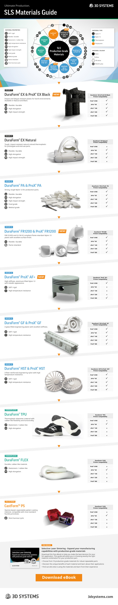
DuraForm® EX & ProX® EX BlackDuraForm® EX NaturalDuraForm® ProX® AF+DuraForm® TPUDuraForm® FLEXDuraForm® HST & ProX® HSTCastForm™PSDuraForm® PA & ProX® PADuraForm® FR1200 & ProX® FR1200DuraForm® GF & ProX® GFSLSProduction GradeMaterialsNEW!NEW!NEW!Flexible / durableFlame retardantStiff / rigidHigh temperature resistanceStiff / rigidHigh temperature resistanceStiff / rigidHigh temperature resistanceSLS Materials GuideUltimate Production.NEW!DuraForm® EX & ProX® EX BlackDuraForm® EX NaturalDuraForm® PA & ProX® PADuraForm® FR1200 & ProX® FR1200DuraForm® ProX® AF+DuraForm® GF & ProX® GFDuraForm® HST & ProX® HSTDuraForm® TPUDuraForm® FLEXCastForm™ PSNYLON 11NYLON 11NYLON 12NYLON 12NYLON 12NYLON 12NYLON 12THERMOPLASTICTHERMOPLASTICPOLYSTYRENEFREE EBOOK!DuraForm ® EX & ProX ®EX BlackPrinter Compatibility ProX ® 6100 sPro™ 60 sPro™ 140 sPro™ 230 ProX ® 500DuraForm ® EX Natural Printer Compatibility ProX ® 6100xsPro™ 60 sPro™ 140 sPro™ 230ProX ® 500xDuraForm ® PA & ProX ® PA Printer Compatibility ProX ® 6100 sPro™ 60 sPro™ 140 sPro™ 230 ProX ® 500DuraForm ® FR1200 Printer Compatibility ProX ® 6100 sPro™ 60 sPro™ 140 sPro™ 230 ProX ® 500DuraForm ® ProX ® AF+ Printer Compatibility ProX ® 6100sPro™ 60x sPro™ 140x sPro™ 230xProX ® 500DuraForm ® GF & ProX ® GF Printer Compatibility ProX ® 6100 sPro™ 60 sPro™ 140 sPro™ 230 ProX ® 500DuraForm ® HST & ProX ® HSTPrinter Compatibility ProX ® 6100 sPro™ 60 sPro™ 140 sPro™ 230 ProX ® 500DuraForm ® TPU Printer Compatibility ProX ® 6100xsPro™ 60sPro™ 140x sPro™ 230x ProX ® 500xDuraForm ® FLEX Printer Compatibility ProX ® 6100xsPro™ 60sPro™ 140x sPro™ 230x ProX ® 500xDuraForm ® FLEX Printer Compatibility ProX ® 6100xsPro™ 60sPro™ 140x sPro™ 230x ProX ® 500xFlexible / durable High elongationHigh impact strengthFlexible / durable High elongationHigh impact strengthFlexible / durable High elongation High-impact strength Food gradeMedical gradeImpact and fatigue resistant plastic for harsh environments. Available in Natural and Black.Tough, impact-resistant natural colored thermoplastic for prototypes and end-use parts.Strong, tough Nylon 12 for production parts.FAR 25.853 and UL 94-V2 compliant flame retardant Nylon 12 plastic with excellent surface finish.High stiffness, aluminum-filled Nylon 12 with metallic appearance.A glass-filled engineering plastic with excellent stiffness.A fiber-reinforced engineering nylon with high temperature resistance.Thermoplastic elastomer material with rubber-like flexibility and functionality.Durable, rubber-like material.Styrene-based, expendable pattern casting material, compatible with most standard foundry processes.Selective Laser Sintering - Expand your manufacturing capabilities with production-grade materialsDownload this free eBook to help you make the best decision for your SLS application. This guide will assist you in choosing exactly the right material combination for your production part.• Choose from 10 production-grade materials for robust repeatable parts • Discover the unique benefits of each material and learn about their applications• Find out who else is using the materials and learn from their experienceElastomeric / rubber-likeHigh elongationElastomeric / rubber-likeHigh elongationShort burnout cycleMATERIAL TYPE Nylon 11Nylon 12Thermoplastic PolystyreneMATERIAL COLOUR Black WhiteOff-whiteMetallic greyNEW!NEW!Download eBookMATERIAL PROPERTIES Stiff / rigid Flexible / durable Elastomeric / rubber-like High temperature resistance High elongation High impact strength Food grade Medical grade Flame retardantShort burnout cycleSelective Laser SinteringExpand your manufacturing capabilities with production-grade materialsThe Ultimate 3D Manufacturing Solution。

User's manual ESLS 900WHBefore fi rst use, please read all instructions contained in this user manual carefully, even if you are already familiar with using similar products. Only use this product in accordance with the instructions described in the user manual. Keep the user's manual in a safe place where it can be easily retrievedfor future use.Save the original packaging, material, warranty card and proof of purchase receipt, at least for the duration of the warranty policy. If you need to ship this product, pack it in the original cardboard boxto ensure maximum protection during shipping or transport (e.g., when moving or when you need to send this product for repair).E SLS 900WHCONTENTSIMPORTANT SAFETY NOTICE (3)INTRODUCTION (4)OPERATI ON (4)MAINTENANCE AND CLEANING (5)TROUBLESHOOTING (5)DISPOSAL OF USED BATTERIES (5)TECHNICAL SPECIFICATIONS (5)DISPOSAL OF USED ELECTRICAL AND ELECTRONIC EQUIPMENT (6)INSTRUCTIONS AND INFORMATION REGARDING THE DISPOSAL OF USED PACKAGING MATERIALS (6)SLS 900WH EIMPORTANT SAFETY NOTICE1) Carefully unpack the product and take care not to throw away any part of the packaging beforeyou fi nd all the parts of the product.2) This product must not be used by persons (including children) with mental disabilities, weakstrength or by inexperienced persons, unless properly trained or schooled in the safe use of the product, or unless they have been properly supervised by a qualifi ed person who will be responsible for their safety.3) Children must be supervised to ensure that they do not play with the appliance.4) Under no circumstances should you try to repair or alter the product on your own — danger ofelectric shock! Entrust all repairs and adjustments to a specialised company/service. If you open the product during the warranty period, you run the risk of voiding the warranty.5) Only store and use the product away from fl ammable or volatile materials and solutions.6) Keep the product away from extreme temperatures, direct sunlight and excessive humidity. Do notuse in a dusty environment.7) Do not place the appliance near heaters, open fi res and other sources of heat.8) This product is designed for household use. Do not use in industrial surroundings or outdoors!9) Do not use the product for purposes other than those intended.10) Do not spray the product with water or any other liquid. Do not pour water or any other liquidsinto the product. Do not submerge the product in water or any other liquid.11) If you will not be using the product for an extended period of time, remove the batteries. Other-wise they may leak inside the product and cause irreparable damage.12) T he manufacturer is not responsible for damages caused by incorrect use of this appliance or itsaccessories. Such damages include food spoilage, injuries, burns, scalding, fi re, etc.E SLS 900WHINTRODUCTIONThis digital travel luggage scale is used primarily for weighing luggage when travelling by airplane and prevents unpleasant situations where it is necessary to pay signifi cant surcharges for luggage that is over the weight limit set by the airline companies.It can, however, also be used for weighing parcels, fruit and vegetables in buckets during harvesttime, etc.OPERATION1) Pull the nylon strap through the handle of the luggage that you wish to weigh.2)3) Press the button on the scale. The display will show …8888” and the selected weight measuringunit. While the …8888” symbol is shown on the screen you can repeatedly press the button to change the weight measuring unit (kg --> st --> lb).4) After about two second the scale will be ready for weighing (…0.0” will be shown on the display).5) Now carefully lift the scale together with the luggage in such a way that no part of the luggage istouching the ground or the mat that it is on.WarningWhile weighing, hold the scale in a horizontal position and watch the display as you lift it so asnot to overload it by a piece of luggage that is too heavy.6) After measuring the weight of the weighed item, the measuring unit will fl ash twice and remain7) Turn off the scale by holding down the button for 3 seconds.Protection against overloadThis scale is equipped with a sensor against overload. If any overload occurs, the display will show the warning symbol ”EEEE“.Automatic shut off functionYour scale is equipped with an automatic shut off function. This function will turn the scale off if no activities are detected within 30 seconds.SLS 900WH E Switching between weight unitsYour scale is equipped with a weight unit switch, which enables you to display the weight in different units. If you want to switch between metric (kilograms) and imperial units (pounds or stones), move the switch on the rear of the scale to the applicable position (kg --> st --> lb). The change in units will be shown on the display of the scale.Note1 lb (pound) = 0,45 kg1 st (stone) = 6,35 kgChanging the batteryIf “Lo“ is displayed, you need to replace the battery.Using a cross head screwdriver, unscrew the battery compartment cover located on the underside of the scale and replace the battery with a new one. Ensure to maintain the correct polarity (the positive poleof the battery must always point in the upward direction).MAINTENANCE AND CLEANINGTo clean the outer parts of the scale, use a soft cloth dipped in lukewarm water. Do not use harsh clean-ing fl uids, paint thinners or solvents. These can damage the surface of the appliance.TROUBLESHOOTINGIf the scale is displaying random values or if it is not turning off automatically, you need to restart it.In such cases, remove the battery for about 10 seconds and place it back again. The scale should startto work normally.DISPOSAL OF USED BATTERIESThis product comes with an alkaline battery. Used batteries do not belong in domestic waste.Instead, use the appropriate waste collection and recycling centres.TECHNICAL SPECIFICATIONSPower supply ................................................................................................... 3V lithium battery (CR2032) Measuring range ..............................................................................................................................0 – 50 kg Resolution ..............................................................................................................................................100 g Switching between weight units ...........................................................................................kg --> lb --> st Visible display size .......................................................................................................................62 x 29 mm Dimensions (w x d x h) .......................................................................................................149 x 30 x 47 mm Weight .....................................................................................................................................................95 gE SLS 900WH。

Mini slides SLS/SLF2d Internet: /catalogue/...Subject to change – 2023/10Mini slides SLS/SLFKey featuresGeneral • Double-acting drives • Precise and rigid guide • Versatile air connections •Sensors can be integrated• Highly flexible thanks to versatile assembly and mounting options on:– Drive body – Slide – Yoke plateMini slide SLS• Slim design• Integrated end-position cushioning:– Elastic cushioning componentsMini slide SLF• Flat design• Adjustable end-position cushioning – Elastic cushioning components• Versatile combination options on:– Drives• System product for handling and assembly technologyPiston diameter Width (W) x Height (H)6 mm 46 x 11 mm 10 mm 48 x 15 mm 16 mm62x21 mm32023/10 – Subject to changed Internet: /catalogue/...Mini slides SLS/SLFKey featuresVersatile Mini slide SLSMini slide SLF22531534[1] Mounting surface:The drive can be directly attached via through-holes or threaded holes (with appropriate screws).[2] Mounting surface:Devices and loads can be directly attached via threaded holes in the slide and the yoke plate (with appropriate screws).[3] Versatile air connections[4] Adjustable end-position cushioning systems on SLF-...-P-Awith elastic cushioning components in the end positions [5] Sensors can be integrated Sensor slots for one or more proximity switches SME/SMT-10. For space-saving, reliable sensing of piston positions. Proximity switches canbe freely moved and clamped in the sensor slots provided.Mini slides SLSType codes4d Internet: /catalogue/...Subject to change – 2023/1052023/10 – Subject to changed Internet: /catalogue/...Mini slides SLSPeripherals overview21Mini slides SLSData sheet-N- Diameter6 ... 16 mm -T-Stroke length5 ... 30 mm -É-1)Must be throttled externally.1)Note operating range of proximity switches.1)Loads moved by the slides must be taken into consideration when calculating the end-position cushioning energy.2)Note also the graph illustrating piston speed as a function of payload a page 86d Internet: /catalogue/...Subject to change – 2023/1072023/10 – Subject to changed Internet: /catalogue/...Mini slides SLSData sheetMaterialsSectional view14532Mini slides SLSData sheetPiston speed v as a function of payload mSLS-6/-10/-16-...-P-AThe indicated torques refer to thecentre of the guide.These values must not be exceededduring dynamic operation. Specialattention must be paid to thedeceleration phase.If the drive is simultaneously subject-ed to several of the forces and torquesffff vvvv=�FFFF yyyy1�FFFF yyyy2+|FFFF zzzz1|FFFF zzzz2+|MMMM xxxx1|MMMM xxxx2+�MMMM yyyy1�MMMM yyyy2+|MMMM zzzz1|MMMM zzzz2≤1indicated below, the following equa-tion must be satisfied in addition tothe indicated maximum loads:Position of the guide centre+ plus stroke length8d Internet: /catalogue/...Subject to change – 2023/10Mini slides SLSData sheetL21 = 36 mm from tableF y= 0 NF z= m x g= 0.495 kg x 9.81 m/s2 = 4.856 NM x= m x g x L y= 0.495 kg x 9.81 m/s2 x 20 mm = 0.097 NmM y= m x g x [(L21+Hub)-L x]= 0.495 kg x 9.81 m/s2 [(36 mm + 20 mm) – 5 mm] = 0.248 Nm M z= 0 Nm Combined load:ffff vvvv=�FFFF yyyy1�FFFF yyyy2+|FFFF zzzz1|FFFF zzzz2+|MMMM xxxx1|MMMM xxxx2+�MMMM yyyy1�MMMM yyyy2+|MMMM zzzz1|MMMM zzzz2≤1=0+ 4,856 NN150 NN+0,097 NNNN1,1 NNNN+0,248 NNNN1,1 NNNN+0=0,345 ≤192023/10 – Subject to change d Internet: /catalogue/...Mini slides SLSData sheet10d Internet: /catalogue/...Subject to change – 2023/10Peripherals overview3132Type codesH- -NoteEnd stops must not be removed.-N- Diameter6 ... 16 mm -T-Stroke length10 ... 80 mm -É-1)Must be throttled externally.1)Note operating range of proximity switches.1)Loads moved by the slides must be taken into consideration when calculating the end-position cushioning energy.2)Note also the graph illustrating piston speed as a function of payload a page 16MaterialsSectional view41352Piston speed v as a function of payload mSLF-6/-10/-16-...-P-Acentre of the guide.These values must not be exceededduring dynamic operation. Specialattention must be paid to thedeceleration phase.If the drive is simultaneously subject-ed to several of the forces and torquesffff vvvv=�FFFF yyyy1�FFFF yyyy2+|FFFF zzzz1|FFFF zzzz2+|MMMM xxxx1|MMMM xxxx2+�MMMM yyyy1�MMMM yyyy2+|MMMM zzzz1|MMMM zzzz2≤1 indicated below, the following equa-tion must be satisfied in addition tothe indicated maximum loads:Position of the guide centre+ plus stroke lengthL21 = 25 mm from tableF y= 0 NF z= m x g= 0.495 kg x 9.81 m/s2 = 4.856 NM x= m x g x L y= 0.495 kg x 9.81 m/s2 x 20 mm = 0.097 NmM y= m x g x [(L21+Hub)-L x]= 0.495 kg x 9.81 m/s2 [(25 mm + 20 mm) – 5 mm] = 0.194 Nm M z= 0 Nm Combined load:ffff vvvv=�FFFF yyyy1�FFFF yyyy2+|FFFF zzzz1|FFFF zzzz2+|MMMM xxxx1|MMMM xxxx2+�MMMM yyyy1�MMMM yyyy2+|MMMM zzzz1|MMMM zzzz2≤1=0+ 4,856 NN150 NN+0,097 NNNN1,1 NNNN+0,194 NNNN1,1 NNNN+0=0,297 ≤1Mini slides SLF Data sheet21 2023/10 – Subject to change d Internet: /catalogue/...Mini slides SLS/SLFAccessories1)Scope of delivery: 10 per pack22d Internet: /catalogue/...Subject to change – 2023/10Mini slides SLF AccessoriesAdapter kit HAPS Material:Wrought aluminium alloyRoHS-compliantH--NoteThe kit includes the individualmounting interface as well as thenecessary mounting material.1)Corrosion resistance class CRC 1 to Festo standard FN 940070Low corrosion stress. Dry internal application or transport and storage protection. Also applies to parts behind covers, in the non-visible interior area, and parts which are covered in the application (e.g. drive trunnions).2)Packaging unit quantity.23 2023/10 – Subject to change d Internet: /catalogue/...。

SL-SL-SLSSLS 水流开关概述用于感受流过管道的液体流量的变化,起到断流保护。
根据不同的流量需要,开关可以进行调节。
本开关采用的是大负载单刀双掷(SPDT )微动开关,具有快速动作的特点,确保了开关的瞬时性。
外壳设计采用全密封结构,内部构件选用不锈钢耐腐蚀材料,确保开关在任何环境下正常工作。
流体温度0~120℃。
流量开关流向片的调整方法SL-SLS 出厂时装有可拆卸的1英寸、2英寸、3英寸及附加的6英寸流向片,如果需要其它尺寸,可按模板修剪流向片,其圆弧与管道相配。
流量开关一定要安装到一段直线管道上,其两边至少有5倍管径的直线行程。
开关安装时,其接线端子应在易于接线的位置。
SL-SLS 流量开关不能遭受水击,如在流量开关下游装有快速闭合阀,必须使用合适的节流器。
流量开关可安装在水平管道或液流方向向上的垂直管道中,但不能安装在液流向下的管道中。
当安装在液流向上的管道时,因需要考虑重力影响,开关应调节到略高于典型流注析:①“*”根据管的尺寸计算流量值。
②“+”GPM值使用于6″流向片。
对于4″和5″水管,将6″流向片作相应修正。
③“**”开关动作参考开关动作图。
调节流量开关步骤:第一步:取下SL-SLS外壳第二步:调高流量值,顺时针旋转调节螺丝。
想调低流量值,逆时针旋转调节螺丝。
第三步:通过按动主杠杆数次,发现杠杆回复时没有“咔嗒”声表明流量开关低于初设定值。
注:开关已出厂设定约为最小流量值,(参见典型流量表)。
不得调至出厂设定值,因为这有可能造成开关不能回复到“无液流”的位置。
流量开关流向片的调整安装示意图。

SPECIFICA TIONSSLSC-1220132 Channel, 5 V to 33 V, Digital Input/OutputSLSC module design specification version 1.0SLSC compatibility level1Rear I/O compatibility category[01] (digital input/output up to 32 channels) Recommended RTI RTI-12301Front I/O CharacteristicsNote The 32 front I/O channels are organized into two banks consisting of twoports with eight channels per port. Port0 and Port1 are in Bank0; Port2 and Port3 arein Bank1. At least one Vsup must be present and routed to the banks. Each bank canbe powered by either Vsup_0 or Vsup_1.Note The mapping between the 32 rear I/O channels and the 32 front I/O channelsis one-to-one. DIO0 maps to P0.0, and DIO31 maps to P3.7.Number of channels32 bidirectional channelsOvervoltage protection±60 VSynchronization jitter±12.5 nsExternal supply voltage (Vsup) 5 V DC to 33 V DCUndervoltage lockout at 4 VPower-on configuration Software configurable (factory default issinking digital input)Table 1. Feature Configurability (Continued)Digital InputInput type Sinking or sourcingInput voltage range0 V to 5 V0 V to 33 VThreshold voltage settling time20 msMinimum pulse width100 nsMaximum signal frequency100 kHzPropagation delay200 nsSourcing input pull-up resistor24 kΩDigital OutputOutput type Sourcing, sinking, or push-pull Continuous output current50 mA maximumOutput impedance sourcing30 ΩOutput impedance sinking20 ΩShort circuit protection10 channels simultaneous fault Minimum pulse width100 nsMaximum signal frequency100 kHzPropagation delay300 nsRise/fall time25 ns (push-pull configuration) Maximum load capacitance 1 nF maximum2| | SLSC-12201 SpecificationsRear I/O CharacteristicsConnector XJ3 connects to an NI digital input/digital output device supporting 5 V TTL or 3.3 V LVTTL signaling.Power RequirementsPower consumption from backplane 4.1 W maximum5.7 W maximumPower consumption from Vsup under noloadMinimum Vsup power supply outputcurrent capability 1.0A+50mA×BBB BBBBℎBBBThermal dissipation< 50 WPhysical CharacteristicsSLSC slots1Dimensions175 mm × 31 mm × 336 mm (6.89 in. × 1.19in. × 13.21 in.)Weight581 g (20.5 oz)Front I/O connectors2x 44-pin high-density D-SUBRear I/O connectors1x 110-pin Hard Metric type A. 1x 8-bladeUniversal Power Module (UPM), capable ofimplementing Fully Compatible Rear I/O Safety VoltagesMeasurement category OIsolationChannel-to-channel NoneChannel-to-earth ground NoneCaution Do not connect the SLSC-12201 to signals or use for measurementswithin Measurement Categories II, III, or IV.Note Measurement Categories CAT I and CAT O are equivalent. These test andmeasurement circuits are for other circuits not intended for direct connection to theSLSC-12201 Specifications| © National Instruments| 3MAINS building installations of Measurement Categories CAT II, CAT III, orCAT IV.Caution Do not operate the SLSC-12201 in a manner not specified in thisdocument. Product misuse can result in a hazard. You can compromise the safetyprotection built into the product if the product is damaged in any way. If the productis damaged, return it to NI for repair.SafetyThis product is designed to meet the requirements of the following electrical equipment safety standards for measurement, control, and laboratory use:•IEC 61010-1, EN 61010-1•UL 61010-1, CSA C22.2 No. 61010-1Note For UL and other safety certifications, refer to the product label or the OnlineProduct Certification section.Electromagnetic CompatibilityThis product meets the requirements of the following EMC standards for electrical equipment for measurement, control, and laboratory use:•EN 61326-1 (IEC 61326-1): Class A emissions; Basic immunity•EN 55011 (CISPR 11): Group 1, Class A emissions•EN 55022 (CISPR 22): Class A emissions•EN 55024 (CISPR 24): Immunity•AS/NZS CISPR 11: Group 1, Class A emissions•AS/NZS CISPR 22: Class A emissions•FCC 47 CFR Part 15B: Class A emissions•ICES-001: Class A emissionsNote In the United States (per FCC 47 CFR), Class A equipment is intended foruse in commercial, light-industrial, and heavy-industrial locations. In Europe,Canada, Australia and New Zealand (per CISPR 11) Class A equipment is intendedfor use only in heavy-industrial locations.Note Group 1 equipment (per CISPR 11) is any industrial, scientific, or medicalequipment that does not intentionally generate radio frequency energy for thetreatment of material or inspection/analysis purposes.Note For EMC declarations and certifications, and additional information, refer tothe Online Product Certification section.4| | SLSC-12201 SpecificationsCE ComplianceThis product meets the essential requirements of applicable European Directives, as follows:•2014/35/EU; Low-V oltage Directive (safety)•2014/30/EU; Electromagnetic Compatibility Directive (EMC)EnvironmentalModule operating temperature0 °C to 85 °C1 (Tested in accordance withIEC 60068-2-1 and IEC 60068-2-2)Storage temperature range-40 °C to 85 °C (Tested in accordance withIEC 60068-2-1 and IEC 60068-2-2.) Relative humidity range, operating10% to 90%, noncondensing (Tested inaccordance with IEC-60068-2-78.)Relative humidity range, storage5% to 95%, noncondensing (Tested inaccordance with IEC-60068-2-78.)Pollution degree2Maximum altitude2,000 m (800 mbar)(at 25 °C ambient) Indoor use only.Shock and VibrationOperating shock30 g peak, half-sine, 11 ms pulse (Tested inaccordance with IEC-60068-2-27. MeetsMIL-PRF-28800F Class 2 limits) Operating vibration, random 5 to 500 Hz, 0.3 g rms (Tested in accordancewith IEC-60068-2-64)Non-operating vibration, random 5 to 500 Hz, 2.4 g rms (Tested in accordancewith IEC-60068-2-64. Non-operating testprofile exceeds the requirements ofMIL-PRF-28800F Class 3.) 1The chassis internal ambient temperature may reach 85 °C with all slots at the maximum allowedpower dissipation.SLSC-12201 Specifications| © National Instruments| 5Online Product CertificationRefer to the product Declaration of Conformity (DoC) for additional regulatory compliance information. To obtain product certifications and the DoC for this product, visit / certification, search by model number or product line, and click the appropriate link in the Certification column.Worldwide Support and ServicesThe NI website is your complete resource for technical support. At /support, you have access to everything from troubleshooting and application development self-help resources to email and phone assistance from NI Application Engineers.Visit /services for NI Factory Installation Services, repairs, extended warranty, and other services.Visit /register to register your NI product. Product registration facilitates technical support and ensures that you receive important information updates from NI.A Declaration of Conformity (DoC) is our claim of compliance with the Council of the European Communities using the manufacturer’s declaration of conformity. This system affords the user protection for electromagnetic compatibility (EMC) and product safety. You can obtain the DoC for your product by visiting /certification. If your product supports calibration, you can obtain the calibration certificate for your product at /calibration.NI corporate headquarters is located at 11500 North Mopac Expressway, Austin, Texas, 78759-3504. NI also has offices located around the world. For telephone support in the United States, create your service request at /support or dial 1 866 ASK MYNI (275 6964). For telephone support outside the United States, visit the Worldwide Offices section of / niglobal to access the branch office websites, which provide up-to-date contact information, support phone numbers, email addresses, and current events.Information is subject to change without notice. Refer to the NI T rademarks and Logo Guidelines at /trademarks for information on NI trademarks. Other product and company names mentioned herein are trademarks or trade names of their respective companies. For patents covering NI products/technology, refer to the appropriate location: Help»Patents in your software, the patents.txt file on your media, or the National Instruments Patent Notice at /patents. Y ou can find information about end-user license agreements (EULAs) and third-party legal notices in the readme file for your NI product. Refer to the Export Compliance Information at /legal/export-compliance for the NI global trade compliance policy and how to obtain relevant HTS codes, ECCNs, and other import/export data. NI MAKES NO EXPRESS OR IMPLIED WARRANTIES AS TO THE ACCURACY OF THE INFORMATION CONT AINED HEREIN AND SHALL NOT BE LIABLE FOR ANY ERRORS. U.S. Government Customers: The data contained in this manual was developed at private expense and is subject to the applicable limited rights and restricted data rights as set forth in FAR 52.227-14, DFAR 252.227-7014, and DFAR 252.227-7015.© 2017 National Instruments. All rights reserved.377037A-01July 20, 2017。
Safety Laser Scanner Visualization SoftwareFor microScan3 and outdoorScan3Quickstart GuideQuickstart GuideInhalt1. Display scanner data in 7 steps (3)Step 1 – Connect Scanner (3)Step 1.1 – Power Supply (3)Step 1.2 – Ethernet Cable (3)Step 2 – Set up Ethernet Connection (4)Step 2.1 – Read out IP address using Safety Designer (4)Step 2.2 – Read out IP address on display of safety laser scanner (4)Step 3 – Download Software (4)Step 4 – Preparing SLS Visualization Software (5)Step 4.1 –Edit “executable” file to correct IP address (5)Step 4.2 – Replace IP address (5)Step 4.3 – Save file (6)Step 5 – Preparing the computer for the network connection. (7)Step 6 – Open the SLS Visualization Software (9)Step 7 – SLS Visualization Software is displayed (9)2. Using the SLS Visualization Software on WinCC – Overview (10)WinCC Professional (TIA Portal) (10)WinCC Advanced (TIA Portal) (11)Quickstart Guide – Safety Laser Scanner Visualization Software This document describes the steps to run the SLS Visualization Software for microScan3 and outdoorScan3.Pre-requisites:Windows PC (Win XP and up).o Note 1: The SLS Visualization Software does not run on Windows CE.W indows CE has reached End of Life Support in 2018; therefore SICK cannotprovide the SLS Visualization Software for Windows CE.o Note 2: Many SIEMENS HMI's using TIA Portal are based on Windows / WinCC → therefore many SIEMENS HMI's are supported.Supported devicesAll microScan3 devices - except all microScan3 Core I/O versionsOnly outdoorScan3 Pro EtherNet IP1. Display scanner data in 7 stepsStep 1 – Connect ScannerFirst, connect the safety laser scanner to the HMI or computer on which the SLS Visualization Software is used.Step 1.1 – Power SupplyConnect scanner to power supply with 24V. Find appropriate cables on .As an example, the following cable can be used for power connection for microScan3 ProPROFINET:Step 1.2 – Ethernet CableConnect safety laser scanner to HMI or computer using an Ethernet cable. Find appropriate cables on . As an example following cable can be used for microScan3 Pro PROFINET :Step 2 – Set up Ethernet ConnectionThe next step is to set up the Ethernet Connection. In order to do this the IP address of the safety laser scanner needs to be known. There are two simple ways to read it out.Step 2.1 – Read out IP address using Safety DesignerOpen Safety Designer, connect to device (e.g. by using USB cable) and see address on pageaddressing.Step 2.2 – Read out IP address on display of safety laser scannerUse the Buttons on the Safety Laser Scanner. (Device Info Network IP address)Step 3 – Download SoftwareClick link to download the SLS Visualization Software:- SICK Internal: Download here:https:///pages/viewpageattachments.action?pageId=393349683&preview=/393349683/393349693/microScan3-VISU-Diagnostics_V1-0.rar- SICK External: receive Secureshare Link by your SICK Contact.When the download is finished open the ZIP file as follows:Unpack ZIP file to afolder of choiceStep 4 – Preparing SLS Visualization SoftwareWhen the file is unzipped, following files should be included:Step 4.1 –Edit “executable” file to correct IP addressThe IP address that is programmed must be edited before starting the THE SLS VISUALIZATION SOFTWARE.Step 4.2 – Replace IP addressA window will open in which the specified IP address must be exchanged by the address of the safety laserscanner. If you do not have this IP address then go back to “Step 2”.Right click on the file "Execute_192_168_1_5.bat " allows editing of the file.Replace the pre-programmed IP address with the actual IP address of the scanner.Step 4.3 – Save fileOnce the IP address is set correctly safe the executable with its new name. The name should include the actual IP addressStep 5 – Preparing the computer for the network connection.Using Windows computers the connection may have to set in the Control panel. See steps below.Open Network andSharing Center.Go to …Ethernet“Go to “Properties”Go to …Internetprotocol, Version 4 (TCP/IPv4)“Enter the IP address andsubnet mask. Subnet mask is the same asthe scanner.Note that this is the IP address ofthe HMI VISU, not of thescanner. Thus: Same subnet, nutdifferent IP address, however insame range. Confirm …OK“.Step 6 – Open the SLS Visualization SoftwareOpen the bat file.Step 7 – SLS Visualization Software is displayedOpen the bat file that was created previously with the actual IP address in itThe VISU tool will open and should automatically connect to the safety laser scanner.2. Using the SLS Visualization Software on WinCC – OverviewWinCC (TIA Portal) is available in different variants WinCC Basic, WinCC Comfort, WinCC Advanced and WinCC Professional. In addition, there are the two runtime systems WinCC Runtime Advanced and WinCC Runtime Professional. The difference between the variants lies primarily in the configurable devices.WinCC Professional (TIA Portal)With WinCC Professional the THE SOFTWARE DIAG tool can be opened with an exe file via a c script. To do this the following code must be written into the script.WinCC Advanced (TIA Portal)To start the HMI VISU DIAG tool the following software is needed on WinCC Advanced: The tool can then be implemented into the WinCC advanced software.The tool can now be displayed via WinCC Advanced.The …diag2“-Button, will start the defined eventHere you can choose at which event an actionshould be executed. Under …Program name“ youhave to link the tool you want to open.。
十二烷基苯磺酸钠(英文名称:dodecyl benzenesulfonic acid, sodium salt)是一种物质,由C、H、C、Na、O、S等元素组成,也叫做四聚丙烯基苯磺酸钠,白色或淡黄色粉状或片状固体。
溶于水而成半透明溶液。
主要用作阴离子型表面活性剂。
应用阴离子型表面活性剂。
因生产成本低、性能好,因而用途广泛,是家用洗涤剂用量最大的合成表面活性剂,也生产一部分镁、钙等无机盐及三乙醇胺等有机胺盐。
十二烷基苯磺酸钙[27176-87-0]具有优良的乳化性能,是配制各种农药用的混合型乳化剂的重要组成部分。
可由苯与α-烯烃在三氯化铝催化剂下缩合,缩合液经碱洗、水洗后蒸出回收苯,真空蒸馏得到精制烷基苯。
然后用发烟硫酸磺化、白灰中和(在2倍量乙醇中进行),得到十二烷基苯磺酸钙。
用作丙烯酸酯乳液聚合的阴离子乳化剂。
CAS No.:25155-30-0是一种阴离子表面活性剂,其临界胶束浓度为*10-3mol/L烷基苯磺酸钠是黄色油状体,经纯化可以形成六角形或斜方形强片状结晶.具有微毒性,已被国际安全组织认定为安全化工原料,可在水果和餐具清洗中应用。
烷基苯磺酸钠在洗涤剂中使用的量最大,由于采用了大规模自动化生产,价格低廉。
在洗涤剂中使用的烷基苯磺酸钠有支链结构(ABS)和直链结构(LAS)两种,支链结构生物降解性小,会对环境造成污染,而直链结构易生物降解,生物降解性可大于90%,对环境污染程度小。
烷基苯磺酸钠是中性的,对水硬度较敏感,不易氧化,起泡力强,去污力高,易与各种助剂复配,成本较低,合成工艺成熟,应用领域广泛,是非常出色的阴离子表面活性剂。
烷基苯磺酸纳对颗粒污垢,蛋白污垢和油性污垢有显著的去污效果,对天然纤维上颗粒污垢的洗涤作用尤佳,去污力随洗涤温度的升高而增强,对蛋白污垢的作用高于非离子表面活性剂,且泡沫丰富。
但烷基苯磺酸钠存在两个缺点,一是耐硬水较差,去污性能可随水的硬度而降低,因此以其为主活性剂的洗涤剂必须与适量螯合剂配用。
sls小船数显轮中文说明SLC小船数显轮(SLC Digital Wheel)是一种新型的中文输入工具,为用户提供更方便、快捷的中文输入体验。
该系统集合了人类语言理解和计算机智能技术,可以根据用户的输入,自动推断出用户要表达的意思,并将其转化为准确的中文文字。
本文将详细介绍SLC小船数显轮的特点、使用方法以及使用该工具的建议,希望能对广大用户有所帮助。
SLC小船数显轮的特点是其用户友好性和智能化。
通过该工具,用户可以像使用手机键盘一样轻松输入中文,并且无需切换输入法或者记忆繁琐的拼音码表。
SLC小船数显轮能够根据用户的输入上下文,智能地推断用户的意图,并为其提供准确的中文文字选择,大大提高了中文输入的准确性和效率。
使用SLC小船数显轮非常简单。
在输入区域中键入中文字符或拼音,工具会根据用户的输入推断可能的意思,并在候选栏中列出相关的中文词组或单词。
用户只需要通过方向键或鼠标点击来选择正确的词语,即可完成输入。
SLC小船数显轮还支持用户自定义词库和个人习惯词汇的添加,以满足个性化的输入需求。
为了更好地使用SLC小船数显轮,用户可以注意以下几点建议。
首先,保持输入的合理流畅,让工具能够更好地理解用户的意图。
其次,充分利用工具提供的上下文推断功能,尽量不要输入重复的内容,以免造成混淆。
此外,及时更新和管理个人的词库,可以让工具更好地适应个人的输入习惯。
总之,SLC小船数显轮是一款智能化、方便、高效的中文输入工具。
其独特的功能和用户友好的设计,使得中文输入变得更加轻松和愉快。
希望用户们能够充分利用SLC小船数显轮的优势,提升中文输入的速度和准确性。
相信随着科技的不断发展,SLC小船数显轮将会越来越智能化,为用户提供更加出色的中文输入体验。