FAGOR 西班牙法格 洗碗机dishwasher_2008
- 格式:pdf
- 大小:3.39 MB
- 文档页数:35
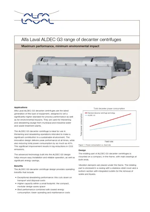
ApplicationsAlfa Laval ALDEC G3 decanter centrifuges are the latest generation of this type of equipment, designed to set a significantly higher standard for process performance as well as for environmental impacts. They are used for thickening and dewatering sludge from municipal and industrial water and waste treatment plants.The ALDEC G3 decanter centrifuge is ideal for use in thickening and dewatering operations intended to make a significant contribution to a sustainable environment. The innovative design delivers peak performance at all times, whilealso reducing total power consumption by as much as 40%. This significant improvement results in big reductions in CO2 emissions.The advanced technology built into the ALDEC G3 design helps ensure easy installation and reliable operation, as well as significant energy savings.BenefitsThe ALDEC G3 decanter centrifuge design provides operating benefits that include•Exceptional dewatering performance: this cuts down ontransport and disposal costs•Higher capacity within a small footprint: the compact,modular design saves space•Best performance combined with lowest energyconsumption: lower operating and maintenance costs Figure 1. Power consumption vs. feed rateDesignThe rotating part of ALDEC G3 decanter centrifuges is mounted on a compact, in-line frame, with main bearings at both ends.Vibration dampers are placed under the frame. The rotating part is enclosed in a casing with a stainless steel cover and a bottom section with integrated outlets for the removal of solids and liquids.1: Gearbox2: Liquid3: Screw conveyor4: Wall of the bowl5: Inlet distributor6: Conical end7: Solids8: Feed inlet9: Discharge ports10: Feed tubeWorking principleSeparation takes place in a horizontal cylindrical bowlequipped with a screw conveyor (see diagram). The feedenters the bowl through a stationary inlet tube and isaccelerated smoothly by an inlet distributor. The centrifugalforce that results from this rotation then causes sedimentationof the solids on the wall of the bowl.The conveyor rotates in the same direction as the bowl, butslightly slower, thus moving the solids towards the conical endof the bowl. The cake leaves the bowl through the solidsdischarge openings into the casing. Separation takes placethroughout the entire length of the cylindrical part of the bowl,and the clarified liquid leaves the bowl by flowing over powertubes into the casing.Features•Power plates/tubes and slimline conveyor design•Critical components made of wear-resistant material•Fully open feed zone for improved separation•360° solids discharge to avoid blocking•Baffle disc provides higher capacity and drier cake solids•Steep or shallow cone configuration for effectiveseparation of any type of slurry•Selection of conveyor designs available for use withdifferent types of slurry•Different forms of wear protection for conveyor flights, tosuit any particular processing requirements•Complete, fully enclosed cleaning-in-place (CIP)Figure 2. Slimline conveyorFigure 3. How power tubes workProcess optimizationALDEC G3 decanter centrifuges can be adjusted to suit specific requirements by varying•Bowl speed to obtain the G-force required for mostefficient separation•Conveying speed for the most efficient balance between liquid clarity and solids dryness•Pond depth in the bowl for the most efficient balancebetween liquid clarity and solids drynessDrive systemIn all ALDEC decanter centrifuges, the bowl is driven by an electric motor and a V-belt transmission drive. Power is transferred to the conveyor via a Direct Drive gearbox. Operation can either be pre-set to a suitable set of parameters, or the difference between the speeds of the bowl and the conveyor can be controlled automatically, with no need for changing belts or pulleys.MaterialsThe bowl, conveyor, inlet tube, outlets, cover and other parts in direct contact with process media are all made of stainless steel.The discharge ports, conveyor flights and feed zone are protected with materials that are highly resistant to erosion. Different types of additional wear protection can be added, including conveyor flights protected with flame-sprayed hard surfacing, and/or sintered tungsten carbide tiles. The larger ALDEC decanter centrifuges are available with an optional full tungsten carbide-covered feed zone for exceptional wear protection.The frame is made of mild steel with an epoxy enamel finish. Different materials are available to meet different requirements.AutomationEvery ALDEC G3 decanter is equipped with a Plus control package as standard, pre-installed and tested in conjunction with each particular unit. The combination of Plus controls with the ALDEC G3 ensures the best possible performance, keeping costs for installation, commissioning, operation andmaintenance to a minimum.Figure 4. Decanter overviewConnectivityALDEC G3 decanter centrifuges can also be fitted with connectivity equipment, to provide users and decision-makers with a wide range of operating data, whether onsite or off.•Remote support enables your service provider to provide remote troubleshooting to help ensure maximumprocessing uptime and keep your ALDEC G3 unit or units running•Remote monitoring ensures greater peace of mind. Access the Alfa Laval connectivity portal to remotely monitor your decanter centrifuge and receive any appropriate alarmnotifications.Technical specificationsDesignation ALDEC G3-75ALDEC G3-85ALDEC G3-105Length (L)4749 mm / 195 in5076 mm / 200 in5861 mm / 231 inWidth (W)1060 mm / 42 in1190 mm / 47 in1300 mm / 51 inHeight (H)1441 mm / 57 in1534 mm / 61 in1696 mm / 67 inMaximum weight3200 kg / 7050 lbs4900 kg / 10800 lbs5000 kg / 11023 lbsMain drive size11-45 kW / 15-75 hp22–75kW / 30–125 hp30-110 kW / 40–150 hpBack drive size7.5-15 kW / 10-20 hp 5.5-22 kW / 7,5–40 hp15- 30 kW / 20-40 hpBack drive control VFD*VFD*VFD**Variable frequency driveDesignation ALDEC G3-115ALDEC G3-125ALDEC G3-165Length (L)6502 mm / 256 in6901 mm / 272 in8672 mm / 342 inWidth (W)1450 mm / 57 in1510 mm / 60 in2040 mm / 81 inHeight (H)1791 mm / 71 in1852 mm / 73 in2248 mm / 89 inMaximum weight6500 kg / 14300 lbs8600 kg / 18959 lbs19000 kg / 42000 lbsMain drive size37-132 kW / 50-200 hp55-250 kW / 75-350 hp132-355 kW / 150-400 hpBack drive size15-30 kW / 20-40 hp22-37 kW / 30-50 hp37-55 kW / 50-75 hpBack drive control VFD*VFD*VFD**Variable frequency driveThis document and its contents are subject to copyrights and other intellectual property rights owned by Alfa Laval Corporate AB. No part of this document may be copied, re-produced or transmitted in any form or by any means, or for any purpose, without Alfa Laval Corporate AB’s prior express written permission. Information and services provided in this document are made as a benefit and service to the user, and no representations or warranties are made about the accuracy or suitability of this information and these services for any purpose. All rights are reserved.200000399-6-EN-GB© Alfa Laval Corporate ABHow to contact Alfa LavalUp-to-date Alfa Laval contact details for all countries are always availableon our website at 。

FTC DISHWASHEROPERATION INSTRUCTIONFTC洗碗机使用说明书高达食品设备有限公司V1.0 0808使用前请完整阅读本手册确保适合的水硬度25-75毫克/升确保餐具彻底的预洗确保只使用专业药剂公司推荐的清洁剂确保每天工作结束时彻底清洁、冲洗、晾干机器(敞开机门)确保按照药剂公司要求定期清除水垢确保只使用已声明对不锈钢无害的产品不要使用硬度过软的水(推荐水的硬度范围25-75毫克/升)不要使用家庭用洗碗清洁剂不要让食物残渣堆积在水箱底部不要让清洁剂、消毒剂、快干剂及除垢剂超过药剂公司推荐的浓度 不要用钢丝球清洁餐具及洗碗机表面不要让杂物进入机器,特别是金属物不要用水龙头等冲洗洗碗机外部注意:不正确的使用及维护造成的机器损坏不在HOBART洗碗机保修范围之内本产品如有设计改动,恕不另行通知目录总览 (1)基本参数 (2)清洗能力 (3)操作 (4)准备-开机前检查 (4)开机 (5)预热 (6)餐具预处理 (7)清洗 (7)紧急停止 (9)过载保护 (9)改变传送带速度 (10)关机 (11)排水 (11)清洁 (11)维护机器的确保与不要 (16)帘子和接水盘 (17)维护 (18)故障排除 (19)变频器设置方法 (22)温控器设置方法 (24)控制板设置方法 (25)FTC DISHWASHER OPERATION INSTRUCTION.FTC系列洗碗机使用说明及注意事项请保留此说明书总览您购买的FTC 系列洗碗机,是全自动智能化长龙洗碗机,具有安全、可靠、方便、快洁、高效、节能、环保等特点。
卓越的模块式设计分为进口模块、预洗模块、清洗模块、主清洗模块、喷淋模块、烘干模块和出口模块(最大配置一个预洗模块、三个主清洗模块、一个喷淋模块和一个烘干模块),可供用户根据需求自由选择(订货时请务必予以注明)。
全不锈钢隔热保温水箱、洗室和低流量环绕式喷淋系统,充分的节省能源,有效降低运行成本。


Baterias inoxStainless steel cookware不锈钢锅具Baterias inox/ Stainless steel cookware / 不锈钢锅具•西班牙法格(FAGOR)集团是欧洲著名的厨房家电及炊具产品的生产者、法国和西班牙市场的领导者、标准的制定者、现代厨房家电及炊具创新产品的倡导者•法格全系列厨房炊具由西班牙著名设计公司DIARA DESIGN倾情设计,遵照行业最高标准,融入浪漫南欧风情,为世界各地的用户呈现经久耐用,风格独特的FAGOR 产品。
•法格FAGOR不锈钢锅具由18/10优质特殊不锈钢(1Gr18Ni10Ti)制造。
锅底采用”钢-铝-钢三层符合工艺.内层18/10高强度、耐腐蚀不锈钢板;中间为高纯度、高导热、铝钢”三层符合工艺内层18/10高强度耐腐蚀不锈钢板;中间为高纯度高导热铝板;外部包有18/0导磁性不锈钢板.适用于燃气灶,电灶,陶瓷灶,电磁灶,卤素灶等多种灶具.Baterias inox/ Stainless steel cookware / 不锈钢锅具选择法格锅具的十大理由Baterias inox/ Stainless steel cookware / 不锈钢锅具选择法格锅具的十大理由Baterias inox/ Stainless steel cookware / 不锈钢锅具选择法格锅具的十大理由Baterias inox/ Stainless steel cookware / 不锈钢锅具选择法格锅具的十大理由Baterias inox/ Stainless steel cookware / 不锈钢锅具法格在中国市场销售的不锈钢锅具产品:法格在中国市场销售的不锈钢锅具产品卡门CARMEN系列是西班牙经典锅型,深受各地消费者的喜爱厚度:0.8mm厚度08工艺:内外沙光钢铝钢三层底Baterias inox/ Stainless steel cookware / 不锈钢锅具法格在中国市场销售的不锈钢锅具产品:法格在中国市场销售的不锈钢锅具产品卡门CARMEN系列奶锅16cm煎炒锅24cm汤锅20cm煎炒锅28cmBaterias inox/ Stainless steel cookware / 不锈钢锅具法格在中国市场销售的不锈钢锅具产品:法格在中国市场销售的不锈钢锅具产品卡门CARMEN系列套装锅:24cm煎炒锅24cm卡门外置蒸框20cm卡门深汤锅Baterias inox/ Stainless steel cookware / 不锈钢锅具法格在中国市场销售的不锈钢锅具产品法格在中国市场销售的不锈钢锅具产品:卡门CARMEN系列精钢中华炒锅30cm三层钢中华炒锅30cm三层钢中华炒锅34cm卡门手柄外置蒸框30cmBaterias inox/ Stainless steel cookware / 不锈钢锅具法格在中国市场销售的不锈钢锅具产品:法格在中国市场销售的不锈钢锅具产品厨师系列厨师CHEF系列是专业厨师爱用的经典欧式锅型,深受各地消费者的喜爱厚度:0.8mm内外光工艺:内外沙光钢铝钢三层底Baterias inox/ Stainless steel cookware / 不锈钢锅具法格在中国市场销售的不锈钢锅具产品:法格在中国市场销售的不锈钢锅具产品厨师CHEF系列奶锅16cm汤锅卡色罗拉24cm汤锅卡色罗拉16cm厨师手柄外置蒸框20cm/24cmBaterias inox / Stainless steel cookware / 不锈钢锅具法格在中国市场销售的不锈钢锅具产品法格在中国市场销售的不锈钢锅具产品:厨师CHEF系列汤锅欧意亚汤锅欧意亚16cm20cm汤锅欧意亚汤锅欧意亚24cm18cmBaterias inox/ Stainless steel cookware / 不锈钢锅具法格在中国市场销售的不锈钢锅具产品:法格在中国市场销售的不锈钢锅具产品格朗GRAN系列秉承创新的设计理念,撷趣西秉创新的计念撷趣班牙南部格拉纳达的建筑风格元素,采用别致的锥型锅身,典雅时尚.锥型锅身,简洁明快;钢化玻璃盖+不锈钢宽边,烹饪过程一目了然;黑色胶木手柄,隔热防滑;精湛点焊工艺,美观牢固;滑;精湛点焊工艺美观牢固;钢铝钢复打底工艺,一如既往为您提供极佳的烹饪性能.厚度:0.7mm工艺:内沙外光钢铝钢三层底Baterias inox/ Stainless steel cookware / 不锈钢锅具法格在中国市场销售的不锈钢锅具产品法格在中国市场销售的不锈钢锅具产品:格朗GRAN系列汤锅20cm煎炒锅24cm汤锅24cm煎炒锅26cmBaterias inox/ Stainless steel cookware / 不锈钢锅具法格在中国市场销售的不锈钢锅具产品:法格在中国市场销售的不锈钢锅具产品玛雅MAYA系列法格全新玛雅系列锅具,设计灵感源自古老神秘文化,整体线条流畅,均衡端庄.衡端庄采用APPLE鼓型锅身,增加实际容量;一体化不锈钢盖,密闭性能极佳;中空手柄,隔热防滑;精湛点焊工艺,美观牢固;钢铝钢复打底工艺,一如既往为您提供极佳的烹饪性能.既往为您提供极佳的烹饪性能厚度:1.0mm厚度:10mm工艺:内外沙光钢铝钢三层底Baterias inox/ Stainless steel cookware / 不锈钢锅具法格在中国市场销售的不锈钢锅具产品法格在中国市场销售的不锈钢锅具产品:玛雅MAYA系列汤锅20cm煎炒锅28cm深汤锅24cmBaterias inox / Stainless steel cookware / 不锈钢锅具法格在中国市场销售的不锈钢锅具产品法格在中国市场销售的不锈钢锅具产品:高精度金刚粒子镜面工新银座经久流行的弧形锅身,提供艺抛光,光亮璀璨,典雅华贵。

洗碗机起源于欧美,1927年德国制造出第一台洗碗机,1956年美国持有洗碗机制造的专利,发展至20世纪90年代餐具清洁市场开始真正分为手洗和机洗两个领域,市场占有率分别为70%和30%。
我国从上世纪70年代开始逐渐步入洗碗机清洗时代,2011年8月22日国家食品药品监督管理局发布的《餐饮服务食品安全操作规范》中对餐具推荐的清洗方法有手工清洗和洗碗机清洗两种,餐饮服务业使用的洗碗机即为商用洗碗机,说明商用洗碗机进入了官方推广的范围。
商用洗碗机是指适用于餐厅、宾馆、饭店等公共场合使用的洗碗机,同时将洗涤、清洁、消毒和干燥融为一体,与家用洗碗机不同的是,商用洗碗机体积更大,具有强度大、短时间处理更多餐具的特点。
对于公共餐具的清洁,手工清洗的清洁过程为:人工去除残渣,将餐具浸泡在加有清洁剂的具有一定温度的固定水槽中用抹布洗碗,将沾有孟 玲(中万恩科技有限公司,北京,100026)摘 要:介绍了商用洗碗机的结构、分类、特点和其专用清洁剂的分类、产品组成、要求,阐述了商用洗碗机能够做到清洁消毒的原因,并对商用洗碗机和专用清洁剂的发展方向做了一些分析。
关键词:公共餐具清洁;商用洗碗机;洗碗机专用清洁剂中图分类号:TQ649 文献标识码:A 文章编号:1672-2701(2020)09-150-06作者简介:孟玲,硕士,主要从事洗涤与消毒产品的技术工作。
E -m a i l : ************************。
清洁剂的餐具放入清水清洗槽中清洗,用抹布擦干,放入消毒柜中消毒,放入保洁柜中储存,这也是较为传统的清洗方式;采用商用洗碗机清洁餐具时的清洁步骤为:拨渣-分类-预洗-主洗-漂洗-完成,整个过程中,只有去除残渣过程、预洗、插盘过程需要人工操作,而这几步的人工操作又极其简单,只需简单培训即可做到规范化操作,而其他过程只需设定好参数,清洁和消毒过程即可一并完成。
采用洗碗机进行餐具清洁,由于清洗过程的规范化、流程化,不仅能够提高清洗效率,保障消毒卫生要求,还能够减少餐具破损、节约水资源、优化人力资源配置,采用商用洗碗机来进行公共餐具的清洁可称得上是对于公共餐具清洁工作的一场小革命。
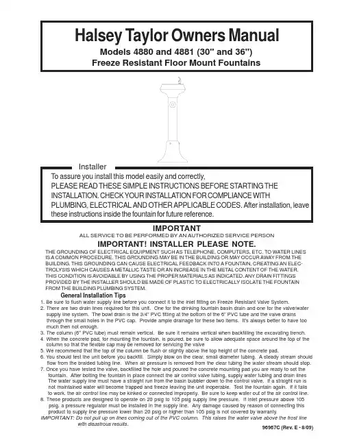
96967C (Rev. E - 8/09)Halsey Taylor Owners ManualModels 4880 and 4881 (30" and 36")Freeze Resistant Floor Mount FountainsIMPORTANTGeneral Installation Tips1. Be sure to flush water supply line before you connect it to the inlet fitting on Freeze Resistant Valve System.2. There are two drain lines required for this unit. One for the drinking fountain basin drain and one for the valve/water supply line system. The bowl drain is the 3/4" PVC fitting at the bottom of the 6" PVC tube and the valve drainsthrough the small holes in the PVC cap. Provide ample drainage for these two items. It's always better to have too much then not enough.3. The column (6" PVC tube) must remain vertical. Be sure it remains vertical when backfilling the excavating trench.4. When the concrete pad, for mounting the fountain, is poured, be sure to allow adequate space around the top of the column so that the flexible cap may be removed for servicing the valve5. We recommend that the top of the column be flush or slightly above the top height of the concrete pad.6. You should test the unit before you backfill. Simply blow on the clear, small diameter tubing. A steady stream should flow from the braided tubing line. When air pressure is removed from the clear tubing the water stream should stop.7. Once you have tested the valve, backfilled the hole and poured the concrete mounting pad you are ready to set the fountain. After bolting the fountain in place connect the air control valve tubing, supply water tubing and drain lines The water supply line must have a straight run from the basin bubbler down to the control valve. If a straight run is not maintained water will become trapped and freeze leaving the unit inoperable. Test the fountain again. If it fails to work, the air control line may be kinked or connected improperly. Be sure to keep water out of the air control line.8. These products are designed to operate on 20 psig to 105 psig supply line pressure. If inlet pressure above 105 psig, a pressure regulator must be installed in the supply line. Any damage caused by reason of connecting this product to supply line pressure lower than 20 psig or higher than 105 psig is not covered by warranty.IMPORTANT: with disastrous results.ALL SERVICE TO BE PERFORMED BY AN AUTHORIZED SERVICE PERSONIMPORTANT! INSTALLER PLEASE NOTE.THE GROUNDING OF ELECTRICAL EQUIPMENT SUCH AS TELEPHONE, COMPUTERS, ETC. TO WATER LINES IS A COMMON PROCEDURE. THIS GROUNDING MAY BE IN THE BUILDING OR MAY OCCUR AWAY FROM THE BUILDING. THIS GROUNDING CAN CAUSE ELECTRICAL FEEDBACK INTO A FOUNTAIN, CREATING AN ELEC-TROLYSIS WHICH CAUSES A METALLIC TASTE OR AN INCREASE IN THE METAL CONTENT OF THE WATER.THIS CONDITION IS AVOIDABLE BY USING THE PROPER MATERIALS AS INDICATED. ANY DRAIN FITTINGS PROVIDED BY THE INSTALLER SHOULD BE MADE OF PLASTIC TO ELECTRICALLY ISOLATE THE FOUNTAIN FROM THE BUILDING PLUMBING SYSTEM.Installation Instructions1. Prepare trench for water supply and waste drain lines (if required by local codes). The hole should be deepenough to accommodate the PVC column and 5 cubic feet of porous fill (large broken rock). Additionalporous fill may be required due to local ground conditions. (See ground Rough-in Detail Page 4)2. Lay drain lines and water supply lines. Provide service shut off valve for maintenance. Flush the water supplyline before attaching to the shut off valve.3. Set PVC column in excavating pit. Connect the water supply line to the inlet on the PVC column. Removevalve assembly from the PVC column by carefully pulling up on the connecting tubing. Pressure test thevalve assembly for leaks. Check operation of the water valve by blowing on the small clear diameter tubing.A steady stream of water should flow from the braided tubing. After releasing air pressure from the smallclear tubing the water stream should stop.4. Replace the water valve into the PVC column. Make sure the supply hose coils into the bottom of thePVC column without any kinks. Cap the PVC column, protect the ends of the connecting tubes and backfillthe trench. Keep the PVC column vertical at all times.5. Form the concrete mounting pad and locate the fountain anchor bolts in the proper position. (Refer toRough-in for correct location of anchor bolts.) Pour concrete and finish. Be sure to keep concrete awayfrom the top of the PVC column to allow removal of PVC cap to allow for future service. Let concrete set24 hours minimum before mounting fountain.6. Double check that the water valve is positioned fully at the bottom of the PVC column. Install insulationinto the PVC column and push down onto the top of the water valve.7. Mount the fountain onto the anchor anchor bolts. Level and shim fountain as required.8. Connect the drain line, water line and air control lines. Excess lengths should be trimmed from the tubing.the water supply line must be positioned for positive drain back out of the fountain and down through thewater valve. Any water allowed to be trapped above the frost line will freeze leaving the unitinoperable. Do not pull up on the connection lines as this could raise the valve above the frost line.9. Check for proper operation by using fountain push button. If the valve does not work properly check forleaks or kinks in the air control line.10. After insuring proper operation reassemble fountain. Installation of your fountain is now complete.TROUBLE SHOOTING AND MAINTENANCEInsufficient Bubbler Flow: Check that the shut-off valve is wide open. Verify minimum 20 PSI supply pressure.Clean inlet strainer screen located in the valve body. Clean rubber orifice in flow control located belowfrost line in bushing between barb fitting and valve.No Flow: Check for leaks in the air tubing going from the push button to the valve. Make sure the air tubing compression nut are hand tight. Disconnect air tube from push button. Place finger over air outlet.Push button to test diaphragm. Tighten diaphragm cap screws. Replace diaphragm if necessary.Continued Insufficient or Varied Height of Bubbler Flow: Replace flow control. Check for kinks in the tubing.Continuous Bubbler Flow: Insure that push button is not obstructed and springs back to normal position.Remove four screws which secure plastic diaphragm block to valve body. Pull plastic and rubberdiaphragm assembly out of valve body. Locate tiny hole in rubber diaphragm just under lip of plasticpart. Clean debris from this hole. Inspect valve seat for grooves. If seat is worn, replace with stainlesssteel seat (Newer Models) or replace valve (Older Models, Integral Brass Seat). If valve seat was OK anddiaphragm hole were free from debris, inspect rubber button located at center of floating steel disc invalve diaphragm block assembly. If button is worn, turn disc over or replace it. If diaphragm and seatsare in good condition, stretch spring slightly. Spring is located behind floating stainless steel plate. Insurethat air bleed port on valve plastic block assembly is not plugged.96967C (Rev. E - 8/09)PAGE 2BACKFILL(DIRT)PAGE 396967C (Rev. E - 8/09)96967C (Rev. E - 8/09)PAGE 4DESCRIPTION10032274056016035154373016001614373056092C 15013C 17073484283040001471375040078771375040078781375040001481375041032280864045357C 45403C 45404C 45851C 50074C 55960C 55961C 66457C 66459C 66461C 70793C 56123C 75565C 10144954255075661C 11001624373011031914389011054494255075523C123456789101112131415161718192021222324252627NSP ART NO.Gasket-BlackWaste Pipe 1" O.D. x 16.50Waste pipe 1" O.D. x 22.50Poly Tubing - 1/4" (Cut to Length) - To Bubbler Bubbler Tube Assy.Receptor Tripod BaseT op-Upper Casting T op-Lower Casting Cover-Base Drain PlugPush Button Valve Adapter Push Button ActuatorSingle Control Valve System BubblerGasket-T ailpipePressure Fitting 1-1/4 to 3/4Pressure Fitting 1-1/4 to 1Tube-Pedestal 4" O.D. x 13.75Tube-Pedestal 4" O.D. x 19.75Connector 1-1/4 x 1-1/4Elbow Fitting 1/4 x 90°Poly Tubing - 1/8" (Cut to Length) - To Actuator Double Male Connecor Clamp-HoseScrew # 8 x .50 Pinned T orx Hex Nut 1-11 1/2Screw-3/8-16 x 3/4Set Screw #8-32 x .125Bit - Pinned T orxITEM NO.PARTS LISTFOR PARTS, CONTACT YOUR LOCAL DISTRIBUTOR OR VISIT OUR WEBSITE 2222 CAMDEN COURT OAK BROOK, IL 60523630.574.3500PRINTED IN U.S.A.12111396WATER LINE 21810875114, 27142015Concrete Slab (By Installer)2422262332116, 17, 19DRAIN LINE 25。


Lavavajillas DishwasherMODELSCOP-174W / HRSFebrero 2015 FebruaryRevisado Julio 2015 July Revised112009104PATAS REGULABLES REGULABLE FEET 4212098018CASQUILLO RODADURA ROLLING BUSHING 2312120608PANEL LATERAL DCHO RIGHT SIDE PANEL 1412120609PANEL LATERAL IZDOLEFT SIDE PANEL 1512110635PANEL POSTERIOR CAPOTA RARE PANEL1612113561PANEL FRONTAL CAPOTA WHOOD TYPE FRONT PANEL W 1712045900TOPE BASE CESTILLO COMPLETO COMPLETE BASKET BASE END 2812045909BASE CESTILLO VARILLA COMPLETA COMPLETE WIRE BASKET BASE 1912095220TAPA CAJA CONEXIONES CONNECTIONS BOX COVER 11012096947JUNTA TAPACOVER'S SEAL11112048609CESTILLO RECOGEDOR CONCEPT CONCEPT DUSTPAN BASKET 11212047947BANDEJA FILTRO CONCEPTCONCEPT FILTER TRAY11312103501JUNTA EPDM CAJA CONEXIONES CONNECTION BOX EPDM JOINT 11412025011CESTILLO BASE CT-10CT-10 BASE BASKET11512102646CESTILLO PLATOS CP-16-18CP-16-18 PLATES BASKET 11612023745CESTILLO CUBIERTOSCUTLERY BASKET81712047509RODILLO ELEVACIÓN CAPÓHOOD ASCENT ROLLER 21812007871TURECA LATON G 5/8" DIN934BRASS NUT G 5/8" DIN93421912009947JUNTA PLANA 32X21X3FLAT SEAL 32X21X322012023739TAPON CROMADO CHROME COVERED CAP 2174 - 2 -N plano / Drawing N.Firma /SignatureFecha / DateAparato / ApplianceLamina / SheetC-337307-20152ASA-CAPOTA / HANDLE HOOD ITEM MARCADO EN COLOR = REPUESTO RECOMENDADOCOLOURED ITEM = RECOMMENDED SPARE PARTIban VAVAJILLAS COP-174W DISHWASHER17611141681543518131920167291221112096877SOPORTE BLOQUEO SEGURIDAD SECURITY LOCK SUPPORT 2212096881VARILLA BLOQUEO SEGURIDAD SECURITY LOCK ROD 2312096882EJE BLOQUEO SEGURIDAD SECURITY LOCK SHAFT 2412096883TAPA BLOQUEO SEGURIDAD SECURITY LOCK COVER2512098128SOPORTE DE GIRO EJE ASA HANDLE AXIS ROD SUPPORT 2612047537TOPE GOMA BIELACONNECTING ROD RUBBER END 4712096710CASQUILLO APOYO MUELLESPRING SUPPORT BUSHING2812098150SISTEMA ELEVACION CAPOTA ADV.HOOD ASCENT SYSTEM ADVANCE 1912098068RODILLO ASA CAPOTA EVO EVO HOOD HANDLE ROLLER 21012098073TORNILLO RODILLO ASA EVO HANDLE ROLLER SCREW 21112048836MUELLE CAPOTA K7.5HOOD SPRING K7.521212093162JUNTA PLANA CARRILGUIDE'S PLANE SEAL21312048915GANCHO ROSCADO M10-L315THREADED HOOK M10-L31521412091140CONJUNTO CAPO SIMPLE PARED SIMPLE WALL HOOD ASSEMBLED 11512024980AMORTIG. RD10FK 140N SUSPA SHOCK ABSORVER RD10FK 140N 11612110409MUELLE SIS. BLOQUEO CAPOTA HOOD'S LOCK SYSTEM SPRING 21712025255CASQUILLO RODANTEROLLING BUSHING11812098217SOPORTE AMORTIGUADOR SHOCK ABSORVER SUPPORT 11912091573CARRIL IZDO CAPOTA HOOD'S LEFT GUIDE 12012091933CARRIL DCHO CAPOTAHOOD'S RIGHT GUIDE 12112010242TORNILLO ESPECIAL M-5X13SPECIAL SCREW M-5X132174- 4 -112046160SOPORTE BOMBA LAVADO WASHIG PUMP SUPPORT 2212102834MOTOBOMBA 590KW 60Hz WASHIG PUMP 590KW 60Hz 2X312023556BASE BOMBA LAVADO 1003016WASHIG PUMP BASE 10030162412047910SOP. DISTRIBUIDOR INFERIOR LOWER SPRY-ARM SUPPORT 1512047688CONDUCTO ASPIRACION 2 BOMB. 2 PUMP SUCTION PIPE 1612046162CONDUCTO ASPIRACION SUCTION PIPE 1712024376CONDENSADOR 10MF 10MF CONDENSER 2X812098457JUNTA CIERRE BRAZO INOX STAINLESS STEEL ARM SEAL 2912009962ABRAZADERA 40-6040-60 CLAMP 81012122473BRAZO LAVAD-ACLAR. CAPOTA WASH-RINSE ARM11112024934SOPORTE DISTRIBUIDOR RUPERIOR UPPER SPRY-ARM SUPPORT 11212103243BRIDA POSTERIOR BRAZO INOX S.STEEL ARM BACK FLANGE11312048171ADAPTADOR RAMAS LAVADO 2 BOMB.WASHING ARMS ADAPTER 2 PUMPS 11412003421DISTRIBUIDOR COMPLETO COMPLETE SPRY-ARM 21512025116CASQUILLO DISTRIBUIDOR SPRY-ARM'S BUSHING 21612023674ARANDELA AMARRE TIGHTEN UP WASHER21712102984DISTRIB. ACLARADO CONCEPT PLUS CONCEPT PLUS RINSE SPRY-ARM 21812112480EJE LAVADO CAPOTA CONCEPT WASHING SHAFT 11912041628PROTECTOR FUGAS ACLARADO RINSING LEAKAGE PROGTECTOR 42012043288TURECA ESPECIAL SPECIAL NUT 22112047689CODO IMPULSION COP110COP110 EXPULSION ELBOW12212047690ARBOL LAVADO COP110 2 BOMBAS COP110 2 PUMPS WASHING TREE 12312113860EJE LAVADO ACLARADO CONCEPT W RINSING SHAFT CONCEPT W 12412043422EJE ACLARADO RINSING SHAFT 2174 - 6 -19022347KIT DOSIFICADOR DETERGENTE EVODETERGENT DISPENSER KIT EVO 112024216DOSIF. DGTE REGULABLE G300DETERG. REGUL. DISPENSER 1X212120598SOP. DOSIFICADORES CAPOTA DISPENSERS SUPPORT1CAPOTA - PASS-THOUGH212046465SOPORTE BOMBA PERISTALTICA PERISTALTIC PUMP SUPPORT 1LAVAVASOS 400212049139SOPORTE DOS. DETERGENTE 12DISPENSERS SUPPORT1LAVAVASOS 350212102040SOP. DOSIF. DETERGENTE AF DISPENSERS SUPPORT FRONT LOAD.1AP.FRONTAL - FRONT LOADING312011355FILTRO ASPIRACIONSUCTION FILTER1412024139CONDUCTO ASPIRACIÓN AZKOY AZKOY SUCTION PIPE 1512024353PESO FILTROFILTER'S WEIGHT1612024531INYECTOR DETERGENTE INOX DETERGENT INJECTOR1711000079CONDUCTO DOSIF. TRANSP 6X4DISPENSER TRANSPARENT PIPE 1812023707BRIDA ELASTICA TUBOELASTIC CLAMP FOR PIPES112024314CABLEADO DOSIF. DETERGENTE DETERGENT DISPENSER WIRING1174- 8 -112048037CUBETA 2 BOMBAS CAPOTA PASS-THROUGH PAIL 2 PUMPS 1212048717JUNTA TORICA O-126.35X5.33O-RING O-126.35X5.331312048039AMARRE CUBETA CAPOTA PASS-THROUGH PAIL FASTENING 1412049652FILTRO COMPLETO CONCEPT COMPLETE FILTER CONCEPT 1512024473MANGUERA DESAGÜE DRAINING PIPE 1X612009962ABRAZADERA 40-6040-60 CLAMP1712120611ALIVIADERO CONCEPT CAPOTAPASSTHROUGH CONCEPT SPILLWAY 1812048748JUNTA TÓRICA ALIVIADERO 37-32-2.5SPILLWAY O-RING 37-32-2.51174112024233BOMBA ACLARADO HANNING HANNING RINSING PUMP 1X212110537SOPORTE BOMBA ACLARADO RINSING PUMP'S SUPPORT 1312041928CONDUCTO CALDERIN-BOMBA BOILER-PUMP HOSE 1412095427 E.V SIMPLE 220V SALIDA A 90ºSIMPLE E.V 90º EXIT1X 512097453CONDUCTO AIREACION CALDERIN BOILER VENTILATION ELBOW 1812092198DOSIFICADOR ABRILLANTADOR RINSE DISPENSER 1X1112023511RACORD EN Y"Y" SHAPED RACCORD 11212024115MANGUERA ENTRADA AGUA WATER SUPPLY HOSE 11312114353TUBO WRASWRAS PIPE11412046080COND. IMPULSION ACLARADO RINSING EXPULSION PIPE 11511000083TUBO GOMA NEGRA D 17x10 D 17x10 BLACK RUBBER PIPE 11611000083TUBO GOMA NEGRA D 17x10 D 17x10 BLACK RUBBER PIPE 11711000083TUBO GOMA NEGRA D 17x10 D 17x10 BLACK RUBBER PIPE 11812114353TUBO WRASWRAS PIPE 11912010023ABRAZADERA 20-3220-32 CLAMP 42012010036ABRAZADERA 12-2012-20 CLAMP 142112011355FILTRO ASPIRACIONSUCTION FILTER12212024139CONDUCTO ASPIRACIÓN AZKOY AZKOY SUCTION PIPE 12312024353PESO FILTROFILTER WEIGHT12411000079CONDUCTO DOSIF. TRANSP 6X4DISPENSER TRANSPARENT PIPE 12512023600CONDENSADOR 5 µF5 µf CONDENSER1X2611000083TUBO GOMA NEGRA D 17x10BLACK RUBBER PIPE D 17x1012712041528TAPON M10x1.5M10x1.5 CAP12811000083TUBO GOMA NEGRA D 17x10BLACK RUBBER PIPE D 17x1012912049052JUNTA 53,57x3,53 SOP DISTR. INF.53,57x3,53 O-RING 130********CALDERIN RECTANGULAR SQUARE BOILER 132********AIR BREAKAIR BREAK1X3312091122JUNTA AIR BREAK AIR BREAK'S SEAL 134********TUERCA AIR BREAKAIR BREAK'S NUT13512040714RACOR EN T ANTIRRETORNOT FITTING NON-RETURN1174112120601BASE CAJA CONEXIONES CONNECTIONS BOX BASE 1212009927PRENSA ESTOPAS PG-21PG-21 CABLE GLAND1312023373BORNES 10 WDU-10203.O 10 WDU-10203.O TERMINAL 3412025224BORNA DE PASO AZULBLUE TERMINAL 2512024743BORNE TIER 10 WPE-10103.O EARTH TERMINAL1612025180REGLETA BORNAJE 2 PISOS 2 LEVEL CONNECTION STRIP 2712025158BORNAS PORTA FUSIBLES FUSE HOLDER TERMINALS 2812024199TOPE FINALFINAL LIMIT1912103361CONECTOR 2 VIAS 10mm 57A 2 WAY CONNECTOR 57A31012103535SOP. CONECTORES 2 VIAS2 WAY CONNECTOR'S SUPP.11112093675PRESOSTAT. DOBLE 125/20-190/165125/20-190/165 PRESSURE SWITCH 1X1211000066TUBO GOMA NEGRO D 8x4 D 8x4 BLACK RUBBER PIPE 11312023707BRIDA ELASTICA TUBOELASTIC CLAMP FOR PIPES21412096597TERM. SEG. 261B 110ºC FAST 90SEC. THERM. 261B 110ºC FAST 901X 1512047752BASE CUADRO ELECTRICO ELECTRIAL PANEL'S BASE 11612024040CONTACTOR 230V 4VIAS UL 230V 4WAY UL CONTACTOR 2X 1712024011CONTACTOR 16A 4VIA UL16A 4VIA CONTACTOR UL2X 1812123408KIT CONTACTOR AUXILIAR 400V UL KIT AUXILIARY CONTACTOR 400V UL 1X 1912024477INTERRUPTOR MAGNETICOMAGNETIC SWITCH1X 2012024066AMARRE INTERRUP. MAGNETICO MAGNETIC SWITCH'S SUPPORT 12112008750CONTROL TARJETA 5 REL. AC 50/60 5 REL. AC 50/60 CONTROL CARD 1X 2212119192EMBELLECEDOR CO-174W CO-174W STICKER1X 2311000162CANALETA 60.30.7760.30.77 CABLE CONDUIT 32412093146CAMPANA TANQUETUB'S PRESSURE CHAMBER 1X 2512093145JUNTA TORICA CAMPANA PRESSURE CHAMBER'S O-RING 12712091478CAMPANA CALDERINBOILER'S PRESSURE CHAMBER 1X 2812118822JUNTA CAMPANA CALDERIN BOILER'S P.CHAMBERS SEAL 1X 2912101852CHAPA REFUERZA CAMPANAP. CHAMBER STRENGTHENER130********PRESOSTATO SIMPLE 1,40-6,30mbar 1,40/6,30mbar SIMPLE PRES.SWITCH 1X 3111000066TUBO GOMA NEGRO D 8x4 D 8x4 BLACK RUBBER PIPE 132********RESISTENCIA 4,5KW TRIPLETRIPLE RESISTOR 4,5KW 1X3312049715SOPORTE RESISTENCIA TANQUETUB RESOSTOR SUPPORT11743412023830LIMITADOR TECASA 125ºC TECASA THERMOSTAT 125ºC 1X 3512022151AMARRE LIMITADOR TECASA TECASA THERMOST. SUPPORT 136********TERMOSTATO 16A 85°C 6MM THERMOSTAT 16A 85°C 6MM 2X3712102004SOPORTE TERMOSTATOTHERMOSTAT SUPPORT138********REGULADOR A 60ºC Tt DE 85ºC 60ºC Tt DE 85ºC REGULATOR 139********RESISTENCIA CALDERIN 12KW BOILER RESISTOR 12KW 1X 4012118319JUNTA TÓRICA RESIS. CALDERIN BOILER RESISTOR'S O-RING 1X4112025036CONJUNTO SONDA 64kOHM NTC 64kOHM NTC THERMOSTAT24212022219SOPORTE COMPO. AD AF-LVS COMPONENTS SUPPORT AD AF-LVS 14312010417VISUALIZADOR LEDS 12V DC UL.LEDS 12V DC UL DISPLAY 1X174112120603CUBIERTA EXTERIOR COMP. C.U. C.U. EXTERNAL COVER 1212048309SERPENTIN C.U.C.U. COOLING COIL 2X312120604BISERA REJILLA C.U.C.U. GRILLED CAP 1411000083CONDUCTO HRS - AIRBREAKHRS - AIRBREAK PIPE1512048319CUBIERTA INTERIOR COMPL. C.U. C.U. INNER COVER COPLETE 1612048323VENTILADOR TANGENCIAL C.U. C.U. TANGENTIAL FAN 1711000083CODUCTO EV - HRSEV - HRS PIPE1812111218JUNTA LAVAVAJILLAS HRSHRS DISHWASHER GASKET 1912009986ABRAZADERA DIN 3017 W2 32-50L DIN 3017 W2 32-50L CLAMP 21012048344TAPA SUPERIOR C.U. C.U. TOP COVER 11112048343CHAPA DE AIRE C.U. C.U. AIR SHEET 11212120605TAPA POSTERIOR C.U.C.U. BACK COVER11312111213CODO ENTRADA VAPOR HRS HRS STEAM INLET ELBOW21411000083TUBO UNIÓN SERPENTINES COOLING COILS CONNECTION PIPE 11512010036ABRAZADERA 12-2012-20 CLAMP 417412009946CABLEADO TENSORTENSIONER WIRING2212114419CABL. PORTAMAN. CO 21, 64, 120, W C.PANEL CO 21, 64, 120, W WIRING 1112120045INSTALACIÓN ELÉCTR CO 120 W UL CO 120 W UL ELECTRICAL WIRING 1112119239CABLEADO HRS HRS WIRING1174 174212102834MOTOBOMBA 590KW 60Hz WASHIG PUMP 590KW 60Hz 22C-3374712024376CONDENSADOR 10MF10MF CONDENSER22C-3374112024216DOSIF. DGTE REGULABLE G300DETERG. REGUL. DISPENSER 11C-3375512024473MANGUERA DESAGÜEDRAINING PIPE11C-3376112024233BOMBA ACLARADO HANNING HANNING RINSING PUMP 11C-3377412095427 E.V SIMPLE 220V SALIDA A 90ºSIMPLE E.V 90º EXIT 11C-3377812092198DOSIFICADOR ABRILLANTADOR RINSE DISPENSER 11C-33772512023600CONDENSADOR 5 µF 5 µf CONDENSER 11C-33773212091121AIR BREAKAIR BREAK11C-33771112093675PRESOSTAT. DOBLE 125/20-190/165125/20-190/165 PRESSURE SWITCH 11C-33781412096597TERM. SEG. 261B 110ºC FAST 90SEC. THERM. 261B 110ºC FAST 9011C-33781612024040CONTACTOR 230V 4VIAS UL 230V 4WAY UL CONTACTOR 22C-33781712024011CONTACTOR 16A 4VIA UL16A 4VIA CONTACTOR UL22C-33781812123408KIT CONTACTOR AUXILIAR 400V UL KIT AUXILIARY CONTACTOR 400V UL 11C-33781912024477INTERRUPTOR MAGNETICOMAGNETIC SWITCH11C-33782112008750CONTROL TARJETA 5 REL. AC 50/60 5 REL. AC 50/60 CONTROL CARD 11C-33782212119192EMBELLECEDOR CO-174W CO-174W STICKER11C-33782412093146CAMPANA TANQUE TUB'S PRESSURE CHAMBER 11C-33782712091478CAMPANA CALDERINBOILER'S PRESSURE CHAMBER 11C-33782812118822JUNTA CAMPANA CALDERINBOILER'S P.CHAMBERS SEAL11C-33783012048644PRESOSTATO SIMPLE 1,40-6,30mbar 1,40/6,30mbar SIMPLE PRES.SWITCH 11C-33783212045886RESISTENCIA 4,5KW TRIPLE TRIPLE RESISTOR 4,5KW11C-33783412023830LIMITADOR TECASA 125ºC TECASA THERMOSTAT 125ºC 11C-33783612040858TERMOSTATO 16A 85°C 6MM THERMOSTAT 16A 85°C 6MM 22C-33783912092825RESISTENCIA CALDERIN 12KW BOILER RESISTOR 12KW 11C-33784012118319JUNTA TÓRICA RESIS. CALDERIN BOILER RESISTOR'S O-RING 11C-33784312010417VISUALIZADOR LEDS 12V DC UL.LEDS 12V DC UL DISPLAY 11C-3378212048309SERPENTIN C.U.C.U. COOLING COIL_2C-3379174 174SCALE:PROPOSED BY:ISSUE DATE:R E V I S I O NSHEET:DOC STATUS:DESING CENTER:SHEET FORMAT:CODETITLENºMATERIAL TREATMENTVALIDATED BY DESIGNED BY -GENERAL TOLERANCES:Very CoarseL I N E A RA N G U L A R<3mm 3-6mm 6-30mm 30-120mm 120-400mm 400-1000mm 1000-2000mm FineMediumCoarse GENERAL TOLERANCE FOR FORM AND POSITION:<10mm 10-50mm 50-120mm 120-400mm >400mm ±0.05±0.05±0.10±0.15±0.20±0.30±0.50±0.10±0.10±0.20±0.30±0.50±0.80±1.20±0.15±0.20±0.50±0.80±1.20±2.00±3.00±1º30'±1º±30'±15'±10'±1º±30'±20'±10'±5'DATE MAT STATUS:Very CoarseFineMediumCoarseVery Coarse±3º±2º±1º±30'±20'ISO 2768-1ISO 2768-2QTY-11Plano Montaje CO 172, COP 174W (120 W)1211449512114495M.Maillo A.G.12.06.2014ONA-A1-LAVAVAJILLAS1:1Ip 12024477n am1V112040923A2A1ag m g m CCn namA1A212024011CTaa a g m nam/vegm n TS R Nam gnam /ve400 V - 3N ~rs 12024274DS DTaMBL211111112 KWSCTSCRcmmam/ve nggn 1vi rs 12023830Tc11111rs11111111111111111111NA111111111111111202437650HZ Z-20101160HZ Z-20351112025183Fusible 4A 12024333Nota:Todos los cables hembra que queden sin conectar se les colocaran una funda para macho Q-57800611111111111rnaP2121114212224vina n m gg m n12023778 Rtam/ve 12103338Leyenda1210318712009927Prensa estopas2112120045teorico Esquema componentes Indicador de 12022162NAMBL150HZ Z-20101160HZ Z-203511m b 12023830TscP111111aC1n C210µFmg11gm n g m nNO NO am rsb maBDviaam/veF bna bn Tst1111111na vi am rs r mCN4CN1SW1CN8CN6CN5CN7CN3P3P2P1R R N TTPT V MBL BD Vreg RG a DIP4321ON ambn b g222222222r naC O P 174C O 172ON 1234ON 1234nm111114Colocar PuenteTt1204085812024040SCSTSTrmaA1A212024011CMBve ramCO 172, COP 174WHCHTmgg mHT HC CONCEPTP3P2P1ON/OFFMod. WHRSnaveam/ve4Mod C 1'nave am amvi 1816A2A115Y14444444444444444444naam44444444444P67naRC, RT ALTERNATINGRC, RT SIMULTANEOUS7676230 V 1 N12345L3L2L1L3L2NL11234512345NL1230 V 3 Ph400 V 3Na12024040A2A1ana NANAg m g m RG n nNC NCgmn g mn 121191741,5mm21,5mm2312na gP31202437610µFm12024233BA120236005uFnaC3m111111111111111COPMod HRS HRS121192392W1211566812114419COPVfamaTCSCALE:PROPOSED BY:ISSUE DATE:R E V I S I O NSHEET:DOC STATUS:DESING CENTER:SHEET FORMAT:CODETITLENºMATERIAL TREATMENTVALIDATED BY DESIGNED BY -GENERAL TOLERANCES:Very CoarseL I N E A RA N G U L A R<3mm 3-6mm6-30mm 30-120mm 120-400mm 400-1000mm 1000-2000mmFineMediumCoarse GENERAL TOLERANCE FOR FORM AND POSITION:<10mm 10-50mm 50-120mm 120-400mm >400mm±0.05±0.05±0.10±0.15±0.20±0.30±0.50±0.10±0.10±0.20±0.30±0.50±0.80±1.20±0.15±0.20±0.50±0.80±1.20±2.00±3.00±1º30'±1º±30'±15'±10'±1º±30'±20'±10'±5'DATE MAT STATUS:Very CoarseFineMediumCoarseVery Coarse±3º±2º±1º±30'±20'ISO 2768-1ISO 2768-2QTY-11Esquema Teorico CO XX2 W, COP XX4 W1211445112114451M.MailloA.gallastegui11.06.2014ONA-A3-LAVAVAJILLAS1:1208-240 V 60Hz,1PhCO-502 W, COP-504 WCO-142W, COP-174 WCO-402 WRtCt RGCc RcRef.12114451RGCcRcCtRtC1MB1MB2C2CMBRtCcRcCtRGHT HCP3P2P1ON/OFFBLUGRNBLUBRNBRN BLKBLK BLKBRN GRYGRY BRN BLK GRY BRN GRY GRYBLK BRN GRYBRN BLK BRN GRYBRN BLKGRY BLKGRYBRN BRN BLK GRY BRN BLK GRY BLK GRY BRNGRN BLUBRNBLK GRY BRN BRN BRN BLK BLKBLK BLKBLK BLKBLKBLKGRY GRY GRYBLUBRNGRYRc=6kW Rc=3kW Rc=6kW 208-240 V, 60Hz,1Ph208-240 V, 60Hz, 3Ph208-240 V 60Hz, 3PhL1L2L1L2L3L1L2NL 123451234512345L1L26.5 kW 15.7A AWG 126.5 kW 27.1A AWG 103.5 kW 14.6A AWG 12CO-142 W 15 kW 36.1A AWG 8COP-174 W 18 kW 43.4A AWG 63.2 kW 13.3A AWG 12CcTcCtIPTtBAbDIP BD RG Vreg BD MBL V PT TT N RRGP213P1P2P3CN2CN3CN7CN5CN6CN8SW1CN1CN4VC1MB1CcDs. DetCCMBMod 142, 174F 10A21241TSCMod.402502504TSTP1213VFMod 402504174Mod 402,502,504YELREDBRNWHTBLKYELWHTBLKYELGRY REDBRN WHT BLUPNKYEL GRYREDORGBLKPNK BLUBLUBLUORGORGPNKPRPPRP BLUBRNScSt GRYBRNORGMod 142174P3Mod 504,174COP 174SW11 2 3 4O N1 2 3 4O NCOP 504CO 112CO 502CO 402S W I T C H B L A C KC O M M U T A T E U R N O I RMod 402,502,172402,502,504ModMod 504,17455s , 80s , 120s -> Mod 172, 17490s, 120s , 180s -> Mod 402, 502, 504,112Drain pumpPompe de vidangeWash - LavageFull Cycle15 "5"20 "CYCLEProgram buttonBouton de programme Rinse - Rinçage 67ORG PRG21HRSTmpA1A2YTmpCMBORGYELORGPRPPNKMod.HRS400 V. 3NL1L2L3N12345LEYENDA APERTURA FRONTAL Y CAPOTATermostato boiler Thermostat kessel Boiler thermostat Thermostat surchauffeur TCPilota macchina preparata Betriebsbereitschaftsanzeigelampe Light machine ready Voyant machine prêtH3Spia avvioStartanzeigelampe Start lightVoyant demarrage H2Spia accensione Betriebsanzeigelampe Operation light Voyant funcionement H1Mikroschalter Tür Micro porta Door microswitch Micro porteIPInterrupteur general Main switchHauptschalterInterruttore generale IGRele porta Türrelais Door relayRelais porte CP Contattore riscaldamento serbatoio Kontaktschütz Heizung Tank Tank heating contactor Contacteur chaufage cuve CtContattore riscaldamento boiler Kontaktschütz Boilerheizung Boiler heating contactor Contacteur chauf. surchauffeur CcContattore pompa lavaggio Kontaktschütz Waschpumpe Wash pump contactor Contacteur pompe lavageCondensatore Kondensator CondenserCondensateurITALIANODEUTSCHENGLISHFRANÇAISESPAÑOLPunti di collegamento con R Anschlußpunkte mit R Conecction point with R Points de conexion R C1, C2, C3CMB A B Dosatore detersivo Dosierer Spülmittel Detergent doserDosseurDs.E.BElectropompe de pression Electric pressure pump Elektro-Drucksteigungspumpe Electropompa pressioneMB1, MB2Pompe lavageWash pumpWaschpumpePompa lavaggioMMoteur du programmateur Motor programmerMotore programmatoreM Av. RM1M2M3M4, M5P1, P3PressostatPressure switchDruckwächterPressostatoR Relais du GenerateurGenerator relay Relais GeneratorRele GeneratoreL1 L2 L3 N Alimentation generateur Water heater feeding Stromversorgungsanschluß Gener.Alimentazione generatore RCResistance surchauffeur Boiler heating element Resistenza boiler RTResistance cuve Tank heater Heizwiderstand Tank Resistenza serbatoio TtThermostat de cuve Tank thermostat Thermostat Tank Termostato serbatoio TstTSCVLimitateur de cuve Limiteur surchauffeur Electrovan. remplissage rinçage Ventilateur tableau electriqueTank limiter Boiler Hi-limitFill and rinse valve Switchboard fanBegrenzer Tank Elektroventil Füllen und Spülen SchalttafelventilatorLimitatore serbatoio Limitatore boilerElettroval. riempimento e risciacquo Ventilatore quadro elettrico12103338Puntos de conexion con RCondensador Contactor bomba lavadoContactor calentamiento calderin Contactor calentamiento tanque Rele puertaDosificador Electrobomba de presion Interruptor general Micro puerta Piloto de encendidoPiloto marcha Piloto maquina preparada Motor programador Motor program. avance rapido Micro programador marcha Presostato Rele de Generador de A.C.Alimentac. Generador A.C.Resistencia calderin Resistencia tanque Termostato tanque Termostato calderin Limitador tanque Limitador calderin Electrovalvula llenado y aclarado Bomba lavado Micro programador lavado Micro programador aclaradoMicro programador avance Ventilador cuadro electrico Moteur du progr.avance rapide Motor program. rapid advance Micro du programm. de marche Micro programmer on Micro du programm. de lavage Micro programmer wash Micro du programm. de rinçage Micro programmer rinse Micro du programm. avance Micro programmer advance Motor Programmiervorrichtung Motor Programmiervorrich. schneller Vorlauf Motor Programmiervorrich. Betrieb Motor Programmiervorrich. Waschen Motor Programmiervorrich. Spülen Motor Programmiervorrich. Vorlauf Heizwiderstand Boiler Begrenzer BoilerMotore programmatore avanzamento rapido Micro programma. di funzionamento Micro programmatore di lavaggio Micro programmatore di risciacquo Micro programmatore avanzamento P2Pressostat de securitéHi-limit pressure switch Begrenzer Druckwächter Pressostato limitatore Presostato limitador Pompa scarico Abflußpumpe Drain pump Pompe de vidange BD Bomba desagüe COLORa = BLU =am = YEL =am/ve = YEL/GRNb = WHT =g = GRY =m = BRN =n = BLK =na = ORG =r = RED =rs = PNK =ve = GRN =vi = PRP =COLORES Azul AmarilloAmarillo/verde Blanco Gris Marrón Negro Naranja Rojo Rosa Verde Violeta COULEURS Bleu Jaune Jaune / vert Blanc Gris Marron Noir Orange Rouge Rose Vert Violet COLOUR Blue YellowYellow / green White Grey Brown Black Orange Red Pink Green Purple FARBEN Blau Gelb Gelb/grün WeißGrau Braun Schwarz Orange Rot Rosa Grün Violett COLORE Blu GialloGiallo/verde Bianco Grigio Marrone Nero Arancio Rosso Roseo Verde ViolaTSTPThermostat Termo-stopTermo-stop Thermostat Thermostat Termo-stopTermostato Termo-stopTermostato termo-stop 升温箱温控器加热完成指示灯开始指示灯运行指示灯门磁开关主开关门继电器水箱加热接触器升温箱加热接触器清洗泵接触器电容中文带R 接触点清洗剂药液泵电子压力泵清洗泵程序电机压力开关热水供应器继电器热水供应器电源线升温箱加热管水箱加热管水箱温控器水箱安全温控器升温箱安全温控器电磁阀风机程序电机.高速高级微程序开微程序清洗微程序喷淋微程序高级高水位限制压力开关排水泵温度停止温控器颜色蓝黄黄/绿白灰棕黑橙红粉绿紫HSalRGVE,BAHRSRinse pump Bomba Aclarado Main RelayRele General Light Lack of Salt Piloto falta de Sal Heat Recovery SystemSistema recuperacion energia Vf VR1, VR2, VR3, BR Electrovalvula Aclarado Frio Cold Water rinse valve Electrovalvula DescalcificacionSoft Water valve。

安全和警告1重要须知!请保留此说明书本说明书显示的型号并非在所有的市场均可买到,而且随时会有变动。
欲了解在本国可购买的机型和规格之最新详情,请访问本说明书最后所列出的本地网站,或者联系当地的斐雪派克 (Fisher & Paykel )经销商。
重要安全提示!安装DishDrawer®抽屉式洗碗机要求您具备基本的机电和电器知识。
必须将说明书留给用户。
必须遵循当地的建筑和电力法规进行安装。
在DishDrawer®洗碗机安装完成后,安装者必须进行最后检查。
除去DishDrawer®洗碗机所有包装。
DishDrawer® DishDrawer®洗碗机仅供室内使用。
确定关闭所有的水管接头。
水电工必须确保所有安装都符合规范和法规。
安装DishDrawer®洗碗机,必须考虑到日后可能需要取出维修。
电源插座必须安装在洗碗机安装的橱柜外,便于安装后插拔。
安装或拆卸本电器时应当小心,避免损坏电源线。
如果要将DishDrawer®洗碗机移动到另一地点安装,必须保持直立,避免因水溢出造成损坏。
务必使用新水管(随机提供)。
不得重复使用旧水管。
如果DishDrawer®洗碗机安装错误,可能导致保修或索赔无效。
如果安装在房车、船或类似移动设施内的产品需要维修,必须自费将房车、船或移动设施带到维修中心;或者,支付维修人员到现场维修的旅途费用。
DishDrawer® 抽屉式洗碗机型号 DD60DDFHX6 & DD60DHI6CN23产品尺寸抽屉式洗碗机尺寸OBCEDFJGHNI安装图仅供参考KLMANGCI产品尺寸 (mm)预制嵌入式门板DD60DD-FHX6整机DD60DDHI6A 产品总高度819.5- 879.5819.5- 879.5B 产品总宽度599599C 产品总深度(不包括曲度/把手)570570D 抽屉深度(开)(不包括曲度/把手)538538E 底板高度*809809F 找平脚高度范围6060G 底板深度(包括密封胶条)552552H 抽屉面板深度(不包括曲度/把手)1818I 曲度或把手深度41无J 踢脚板深度50 - 6567-127**K 上抽屉正面高度398最小398L 下抽屉正面高度311.5最小311.5M 踢脚板高度(可调节)70 - 12070-120N 安装贴片高度(底座顶部)22O抽屉正面高度717.5最小717.5* 机箱高度包括贴片** 减去踢脚板厚度(使用所提供的螺丝的最小板厚为9mm )。


PagiñaSeguridad (65)Mandos (75)Instalación (76)Operación (80)Localización de fallas (83)Mantenimiento (85)Almacenamiento (89)Especificaciónes (90)Garantia (91)Toda información, ilustraciónes, y especificaciones en este manual sebasa en información lo último que disponible al tiempo de publicación. Sereserva el dercho de efectuar combios sin previo aviso.INSPECCIONES UNIDADAsegúrese que todas tapas, guardias, y escudos son ajustados y en posición.Encuentre todos controles operando y etiguetas de seguridad.Inspeccione cordón eléctrico para daño antes de usando. Hay un riesgo de electrocución de aplastante, cortando, o daño de calor.SERVICIO CON CIUDADO UNIDADApague la unidad, desconéctela de la red eléctrica, y permita que la unidad se enfrié antes de repararla.Preste servicio en un área limpie, seca y planca. Embraque el freno para evitar el movimiento de la unidad.A -- GeneradorB -- BombaC -- Cristal De la Vista Del AceiteD -- ManijaE -- Depósito De GasolinaF -- MotorG -- Guardia del cintúronH -- Válvula de descargardel tanque de aireI -- Indicador de presiónAFBGECIA -- GeneradorB -- BombaC -- Cristal De la Vista Del AceiteD -- ManijaE -- Depósito De GasolinaF -- MotorG -- Guardia del cintúron H -- Válvula de descargar del tanque de aire I -- Indicador de presiónAFBGECHIALTITUD ALTAEn altitud alta, la mezcla de aire/combustible del carburador estandard será demasiado rico. Función disminuirá y consumpción de combustible aumentará. Una mezcla muy rica también ensucia la bujía en los motores de gasolina y puede dificultar el arranque. Operación a una altitud que es diferente de altitud donde el motor fue certificado, para una extensión de mucho tiempo, puede aumentar emissiones. Función de altitud alta puede mejorar de modificaciones especificos al carburador. Si siempre operar su unidad a altitudes más de 5,000 pies (1500 metros), su concesionario haga esta función de modificación a carburador. Este motor, cuando operando a altitud alta con modificaciones a carburador para uso en altitud alta, encontrará cada estandard de emissión en toda vida de uso.Con modificación de carburador, caballo de fuerza de motor disminuirá sobre 3.5% para cada 1,000 pies (300-metros) aumento en altitud. Este efecto de altitud en caballo de fuerza será más grande de este si no haga modificación de carburador.NOTA: Cuando el carburador modificó para operación altitud alta, la mezcla de aire/combustible será demasiadodelgado para uso en altitud abajo. Operación aaltitudes abajo de 5,000 pies (1500 metros) concarburador modificado causaría recalentado de motory resultaría en daño serio de motor.Para uso a altitudes abajos, vuelva carburador aconcesionario de servicio a especificados orginalesde fábrica.OPERACIÓNOperación:1. Leer atentamente las advertencias de seguridad antes de efectuaresta operación.NOTA: Desenchufe todo el equipo de los receptáculos de energía antes de comenzar la unidad.2. Colocar muletilla que estar en la arriba de válvula pilota a posición vertical. Este dar una empezada sin descargar. Este compresor de aire puede descargar y tener una empezada de motor más facil.3. Encender el motor. (Referir a manual de este unito de motor.)4. Despues de 1-2 minutos de funcionando, poner muletilla en posición orginal.5. Ajustar la presión moviendo el regulador de presión en el sentido contrario a las manecillas del reloj para reducir la presión y en el sentido de las manecillas del reloj para aumentaria. (La presión real de entrega pueden variar de un nivel de presión máxima de la bomba).6. Asegúrese que unidad toma a tierra. Vea Instrucciones de Conexión a Tierra.7. Cargas pueden aplicar a unidad ahora.NOTA: Este motor está protegido con un sistema que para el motor cuando el aceite alcanza un nivel muy bajo. Elmotor no volverá a arrancar si no se agrega aceite.En caso de ruidos o vibraciones anómalos, detenerel compresor de aire y consultar la sección "Localizaciónde Averías".Apagamiento:1. Quite todas cargas como desconecten cordones électricos y apagadando aparatos électricos.2. Para parar el compresor de aire mover el boton de motora posición de "OFF". (Referir a manual de motor de este unito.)3. Descargar el aire de los depósitos de aire, por medio de una herramienta conectada o tirando los anillos de la válvula de seguridad.4. Una vez que le presión en el interior de los depósitos de aire es inferior a 10 libras, abrir la válvula de descarga debajo de cada depósito de aire para eliminar la humedad.5. Dejar enfriar el compresor de aire.6. Limpiar el compresor de aire con un paño y colocarlo en un lugar seguro, donde no exista el riesgo de congelación.82 Manual del OperadorManual del Operador83Síntoma Problema Soluciones El motor no encender. Varias problemos de motor. Referir a manual de motor de sucompresor de aire.Funcionamiento ruidoso. Polea de motor o bomba de rueda Apretar polea y/o rueda volado. voldao es suelto.Falta aceite en la bomba. Reponer la cantidad de aceitenecesaria. Controlar que los cojinetesno se hayan dañado.Residuos de carbono en los pistones o Desmontar e inspeccionar la culataen las válvulas. del cilindro. Limpiar y sustituir.Avería del cojinete, pistón o biela. PARAR EL COMPRESOR! Póngaseen contacto con la Asistencia Clientes.Abajo de presión en tanque de Los accesorios no han sido apretados Aretar los accesorios donde se oye aire o abajo de presión bien. que el aire dale. Controlar losrapidamente cuando el compresor accesorios con una solución de agua y de aire está apagado. jabón. No apretar demasiado. La válvula de retención y la válvula Desmontar, limpiar o sustituir. piloto es defectuose. Fugas de aire del depósito de aire. Sustituir el depósito de aire. No intentar reparar el depósito.Presión insuficiente en la Fugas de aire. Localizar las fugas y reparar. herramienta o en los accesorios. Filtro aspiración aire obstruido. Limpiar o sustituir.Los tubos o los empalmes de los Sustituir con tubos o empalmes más tubos son demasiado pequeños grandes.o largos.El compresor de aire no produce la Controlar el requisito de aire delcapacidad de aire requerida. accesorio. Si es superior al CMF o a la presión suministrada or el compresor de aire, es necesario usar uncompresor más grande.El regulador de presión no ha sido Ajustar el regulador de presión al ajustado a una presión suficientemente valor adecuado o sustituir. alta o avería del regulador de presión.Las resbalaban de correa. Haga mas apretado o reemplace. Válvula pilota restrica. Limpie o reemplace.El aire sale de la válvula de La válvula de seguridadActivar la válvula de seguridad seguridad. probablemente es defectuosa. manualmente tirando del anillo. La presión de aire en el depósito Si el aire sigue saliendo, debe ser es excesiva. sustituida. Interruptor motor/presióndefectuoso. Sustituir.84Manual del OperadorSíntoma Problema Soluciones No hay salida de voltaje del Arranque de control de marcha en Coloque control de marcha en vacío. unidad.vacío.Serie de cordon o extensiones Revise capabilidades de series de inadecuados. cordon o extensiones.Fugas de aire en la bomba. Juntas defectuosas. Apriete los pernos en el compresor usando la fuerza de torsión correcta oreemplace las empaquetaduras.Soufflement d'air provenant Soupape (reed) d'admission Sustituir.du filtre d'admission d'air. défectuuese.Condensación en el aire de Condensación en el depósito de aire Opera el compresor de aire por una descarga. debido a una elevada humedad hora para impedir demasiadoatmosférica o el compresor de aire condensión. Vaciar el depósito de aire no ha funcionado por un tiempo después de cada empleo. Vaciar el suficiente. depósito de aire más frecuentemente en climas húmedos y usar un filtro enla línea de aire.Excesivo consumo de aceite en Filtro aspiración aire obstrucido. Limpiar o sustituir.la bomba. Compresor de aire sobre superficie No inclinar el compresor de aire no nivelada. a un ángulo superior a 10° en ninguna dirección mientras estéen marcha.Cárter demasiado lleno de aceite. Vaciar el aceite. Reponer con aceitehasta el nivel apropiado.Viscocidad incorrecto. Elimina el aceite. Llene al nivelcorrecto con SAE-30W aceite sin detergente.Pérdidas de aceite. Apriete los pernos en el cabeza del compresor usando la fuerza de torsióncorrecta o reemplace las empaquetaduras.Anillos del pistón desgastados o Ponerse en contacto con la Asistencia cilindro rayado. Clientes.Respirado de cárter es taparo. Limpiar o sustituir.Condensación en el aire de Condensación en el depósito de aire Opera el compresor de aire por una descarga. debido a una elevada humedad hora para impedir demasiadoatmosférica. condensión. Vaciar el depósito de aire después de cada empleo. Vaciar el depósito de aire más frcuentemente en climas húmedos y usar un filtro en la línea de aire.No hay salida de voltaje del Serie de cordon o extensiones Revise capabilidades de series de unidad. inadecuados. cordon o extensiones en sección de Controles; Tamaño de Cable en este manual. Consultar con unconcesionario de distribuidor.Manual del Operador 8586 Manual del OperadorManual del Operador 87(Fig. 3)88 Manual del OperadorManual del Operador 8990 Manual del OperadorANOTE NÚMERO SERIEEscriba número de modelo, numero serie de máquina (vea etiqueta de número serie (A) en ilustración y fecha de compra en espacios abajo. Su concesario necesita esta información cuando ordenando partes.Num. de modelo _________________________________________Num. serie de máquina ___________________________________ Fecha de compra ________________________________________ (llene de comprador)ARTÍCULOESPECIFICACIÓNESUnit *AG2-PH13-08M1 *AG2-SH13-08M1 **AG2-SH13-30M ***AG2-SH13-B *AG2-PS14-08M1 *AG2-SS14-08M1 **AG2-SR14-30M ***AG2-SS14-B*AG2-PK14-08M1*AG2-SK14-08M1 **AG2-SK14-30M ***AG2-SK14-B*AG2-PM14-08M1 *AG2-SM14-08M1 **AG2-SM14-30M ***AG2-SM14-BMotor Honda Subaru Kohler Mi-T -M Motor HP 13141414Aceite (L)1.09 L1.19 L1.30 L0.94 LVatios con el compresor 3500Vatios sin el compresor 3000Tension nominale (V)120V Frecuencia (Hz)60 Hz Bomba Compresor Bifásico Aceite (L)0.73 LDepósito Aire (L)*30.3 L **113.5 L ***N/APresión máximo (psi)175 PSIARTÍCULO ESPECIFICACIÓNESUnit AG1-PH65-08M1AG1-PR07-08M1AG2-SKD-30MMotor Honda Subaru Kohler Motor HP 6.579.1Aceite (L)0.59 L0.59 L1.41Vatios con el compresor 16002750Vatios sin el compresor 6001800Tension nominale (V)120V Frecuencia (Hz)60 HzBomba Compresor Monofásico Bifásico Aceite (L)0.74 L 0.73 L Depósito Aire (L)30.3 L 113.5 L Presión máximo (psi)125 psi175 psiDECLARACIÓN DE GARANTÍAMi-T-M garantiza que todas las piezas (excepto aquellas a las que se hace referencia abajo), de su nueva generador libres de defectos en materiales y mano de obra durante los periodos siguientes:Por dos (2) años a partir de la fecha original de compra:Bomba de Compresor CañeriasTanqueGeneradordeAsambleaPor seis (6) mes a partir de la fecha original de compra:Interruptor de Presión ReguladoresVàlvula de revisar Válvula de pilotoLinea de cobre/acero inoxidablePor noventa (90) días a partir de la fecha original de compra:Indicadores de presión Válvula de alivio de seguridadVálvulas de desagüeLas piezas defectuosas que no están sujetas a deterioro causado por el uso seránreparadas o reemplazadas a nuestra opción durante el periodo de garantía. En todo caso, el reembolso está limitado al precio de compra pagado.EXCLUSIONES1. El motor está cubierto bajo una garantía separada proporcionada por el fabricante respectivo y estásujeta a los términos en ella establecidos.2. Partes de desgaste normal:Aisladores Filtro de aire3. Esta garantía no cubre las piezas dañadas debido al deterioro normal causado por el uso, mala aplicación,mal uso, operación a velocidades, presiones o temperaturas diferentes a las recomendadas. Las piezasdañadas o gastadas a causa del uso de líquidos cáusticos o por la operación en medios ambientesabrasivos o corrosivos o bajo condiciones que causan cavitación de la bomba no están garantizadas.La falla en seguir los procedimientos recomendados de operación y mantenimiento también cancela lagarantía.4. Cobras de trabajar, peridio o daño resultando de operación mala, mantenimiento (otro de descarga detanque de aire rutina y cambios de aceite si aplica) o reparaciones hace por personas otro de Mi-T-MCentro de servicio autorizado.5. El uso de piezas de repuesto diferentes a las genuinas Mi-T-M cancelará lagarantía. Las piezas devueltas, con franqueo pagado a un Centro de Servicio AutorizadoMi-T-M serán inspeccionadas y reemplazadas, libre de cargos, si se determina que están defectuosas ysujetas a la garantía. No existen garantías que se extiendan más allá de la descripción contenida aquí.Bajo ninguna circunstancia Mi-T-M será responsable por la pérdida de uso de la unidad, pérdida detiempo, inconvenientes, pérdida comercial o daños consecuentes.PARA SERVICIO O CONSIDERACION DE LA GARANTIA CONSULTE CON:Mi-T-M® Corporation/50 Mi-T-M Drive, Box 50/Peosta, IA 52068-0050Telefono: 563-556-7484 / 800-553-9053 / Fax 563-556-1235Lunes - Viernes 8:00 a.m. - 5:00 p.m. CSTManual del Operador 9192Manual del Operador Manufactured by Mi-T -M 50 Mi-T -M Drive, Peosta IA 52068563-556-7484/ Fax 563-556-1235。
0442022.02行业解读HANGYEJIEDU1929年,米勒发明了第一台真正意义上的电动洗碗机。
1960年美国的家电品牌商GE生产出第一台GE洗碗机。
同年,日本的松下制造出亚洲地区的第一台洗碗机。
1961年,西门子制造出第一台西门子洗碗机。
1970年Candy也生产出自己的第一台洗碗机。
1987年,澳大利亚的斐雪派克推出抽屉式洗碗机。
1999年,海尔成立洗碗机事业部。
2000年,美的成立洗碗机部门。
即便有海尔、美的和格兰仕等制造企业,中国是世界第一大洗碗机制造基地,但洗碗机是目前国内普及率最低的家电产品之一,一二线城市不到3%。
截止2020年,中国洗碗机的出口量超过500万台。
在欧美等市场,洗碗机从最初被当作奢侈品和公共洗碗用途才开始普及进入家庭的。
那么,在中国洗碗机市场的发展路径需要思考和推敲。
研究发现,因为成长经历不同,中国不同时代的人具有鲜明的消费特征:70后想的是存钱,80后想的是还贷,90后想的是花钱,00后不想钱。
所以,未来洗碗机将会步入中国的千家万户。
全球洗碗机的布局数据显示,全球每年有约2800挖掘中国洗碗机市场的金矿万台的洗碗机进入家庭。
其中,美国家庭洗碗机的普及率接近90%。
其次是欧洲,洗碗机的家庭普及率在60~70%之间。
中国的洗碗机家庭普及率虽然很低,但也贡献了190~220万台的市场规模。
日本和澳洲市场每年洗碗机的市场规模在85万台左右。
中国洗碗机市场未来的规模,需要参考几个数据。
首先是洗衣机。
中国洗衣机的普及率在91.6%左右。
再看日本市场洗碗机的普及率,目前约为30%左右。
参考周边市场和洗衣机的数据可以预测,未来中国洗碗机每年的市场规模要在千万台以上。
中国洗碗机市场的前景与机会既然中国未来的洗碗机市场规模很大,那么,中国家庭需要什么样的洗碗机呢?纵观全球洗碗机市场看,大容积的落地式洗碗机占据了主流市场。
在欧洲市场,大容量落地式洗碗机已经占到了85%的份额;在北美市场大容量落地式洗碗机占到了89%的份额;澳洲市场,大容量落地式洗碗机占到了82%的份额,有15%的是抽屉型洗碗机;日本的洗碗机市场最特殊,抽屉式洗碗机型占到了77%的份额,台式洗碗机也占了超过20%的份额,落地式大容积洗碗机占比很低。
Undercounter DishwashersM4 Series2674 N. Service Road, Jordan Station Ontario, Canada L0R 1S0(905)562-4195 Fax: (905) 562-4618Toll-free: 1(800) 263-57983765 Champion Blvd.,Winston-Salem, NC 27105(336)661-1556 Fax: (336) 661-1660Toll-free: 1(800) 858-4477Issue Date: 8.17.17Manual P/N115440 rev. MFor machines beginning with S/N W140946406 and aboveService Replacement PartsUH130 M4High Temperaturewithout built-in booster Wash Refresh Final Rinse UH130B M4High Temperature with built-in boosterWash Refresh Final Rinse UL130 M4Low Temperature Chemical Sanitization Wash Refresh Final RinseUH230B M4High Temperature with built-in booster Fresh Water Final Rinse UH330B M4.2Condensate Removal High Temperature with built-in booster Fresh Water Final RinseUH230 M4High Temperaturewithout built-in booster Fresh Water Final RinsePrinted in the USATHE MODELS CONTAINED IN THIS MANUAL COMPLYWITH ANSI/ASSE 1001 & ANSI/ASSE 1004.UH330BUH130BCOPYRIGHT © 2017 All rights reserved Printed in the USAFor future reference, record your dishwasher information in the box below.Model Number__________________________ Serial Number_______________________Voltage________________Hertz_____________ Phase__________________Service Agent __________________________________ Tel:______________________Parts Distributor _________________________________ Tel:______________________National Service DepartmentIn Canada:In the USA:Toll-free: (800) 263-5798 Toll-free: (800) 858-4477Tel: (905) 562-4195 Tel: (336) 661-1556 Fax: (905) 562-4618Fax: (336) 661-1660email:******************************email:******************************The USGBC Member Logo is a trademark owned by the U.S. Green Building Council and is used by permission. The logo signifies only that Moyer Diebel is a USGBC member; USGBC does not review, certify or endorse the products or servicesoffered by its members.Service Replacement PartsService Replacement Parts Illustrations PageWash Pump/Motor Assembly - All Models (2)Base Assembly - All Models (4)Fill Piping Assembly - UH130, UH130B, UL130, UH330B (8)Fill Solenoid Valve - UH130, UH130B, UL130, UH330B (10)Fill Piping Assembly - UH230, UH230B (12)Fill Rinse Piping Assembly - UH230, UH230B (14)Final Rinse Piping - UH330B Prior to S/N W170568116 (16)Final Rinse Piping - UH330B Beginning with S/N W170568116 and above (18)Heat Recovery Assembly - UH330B Prior to S/N W170568116 (20)Heat Recovery Assembly - UH330B Beginning with S/N W170568116 and above (22)Booster Heater and Pressure Switches - UH330B Prior to S/N W170568116 (24)Booster Heater - UH330B Beginning with S/N W170568116 and above (26)Booster Hoses and Level Sensor - UH330B Beginning with S/N W170568116 and above (28)Fill Chute Assembly - UH130, UH130B, UL130 (30)Chemical Dispensing Pumps - UH130, UH130B, UH230, UH230B (32)Chemical Dispensing Pumps - UH330B (34)Chemical Dispensing Pumps - UL130 (36)Booster Assembly - UH130B, UH230B (38)Power Input Block and Cord Assemblies - All Models (40)Timer Control Board Assembly - All Models (42)Wash and Rinse Spray Arms and Drain Valve - UH230, UH230B, UH330B (44)Wash/Rinse Spray Arm and Drain Valve - UH130, UH130B, UL130 (46)Control Panel - UH130, UH130B (48)Control Panel - UH230, UH230B (50)Control Panel - UH330B (52)Control Panel - UL130 (54)Panels - UH130, UH130B, UH230, UH230B, UL130 (56)Panels - UH330B (58)Door Assembly - All Models (60)Dish Racks, Line Strainer, PRV (62)1Wash Pump/Motor Assembly - All Models2All Models - Wash Pump/Motor AssemblyItem Part Description Qty. No. No.1 0512347CAPACITOR 40µF 12 0512101PUMP/MOTOR ASSEMBLY COMPLETE 1115VAC/60/13 0313394 BRACKET, WASH PUMP 14 0512185BOLT, HEX FLANGE 1/4-20 X 3/8" SST 25110285G ASKET16114139SEAL170512345IMPELLER18 0501478WASHER, PLAIN, 17/64" 19 106482WASHER, LOCK, 1/4" 110 114144NUT, M6 111 0512340SCREW, M4, PHIL, PAN HD. 912 0512341VOLUTE, PUMP 113 114137BACKPLATE, PUMP 114 107337NUT, M4 915 0513131 COVER, REAR MOTOR FAN 1 NOTE: The pump motor is not sold separately.3Base Assembly - All Models4All Models - Base AssemblyItem Part Description Qty. No. No.1 0512136SCREEN, SCRAP ASSY. 12 0513324FLANGE, PUMP SUCTION 1G A/R 30513677O-RIN4 0512169HEATER, 120VAC 750W) (UL130) 1--- 0512426HEATER, 240VAC 2000W (All except UL130) 1G1 50512099O-RIN6 0508872ADAPTOR, THERMOMETER (UL130 Only) 17 0512107THERMOMETER, WASH TANK (UL130 Only)18 108954NUT, GRIP 6-32 WITH NYLON INSERT SST 29 113604THERMOSTAT, HI-LIMIT BI-METAL SNAP, 212°F 110 0512299ADAPTOR, THERMISTOR 111112612THERMISTOR, 10 KΩ, 2 WIRE ASSY, WASH TANK 1(All except UL130)12 201029-1 NUT, LOCK 1/2 INCH NI PLATED A/R13 0509302HOSE, 5/8" ID X 1" OD A/R14 0513329GASKET, PUMP SUCTION 115 0513325ELBOW, PUMP SUCTION 1160501476WASHER 617 107967NUT, 1/4-20 W/NYLON INSERT SST 618 0502571CLAMP, HOSE 1-1/16" - 2" 219 0512101PUMP/MOTOR COMPLETE 115/60/1 120 0513328HOSE, PUMP SUCTION 121 0512119HOSE, PUMP DISCHARGE 122 0512134TEE, 3/4", POLY. 123 0508808 CLAMP, SS GEAR 224 0313171 HOSE, MOULDED 2-1/2" 125 0312145BRACKET, DRAIN PUMP (UH230, UH230B, UH330B) 15All Models - Base AssemblyItem Part Description Qty. No.No.26 0512227PUMP, DRAIN 115VAC (UH230, UH230B, UH330B) 127 0512322CLAMP, HOSE 228 0513339 HOSE, OVERFLOW (UH230, UH230B, UH330B) 129 0712236 TUBE, OVERFLOW GUARD (UH230, UH230B)1---- 0712236-1 TUBE, OVERFLOW GUARD (UH330B ONLY)130 109835SCREW #8 X 1/2" SELF-TAPPING SST 131 0512185BOLT, HEX FLANGE 1/4-20 X 3/8" SST 132 0509526HOSE, 1/2" X 7 FT. FEM. GARD. ADAPT. 133 0504952VALVE, FILL 5.0 GPM (UH130, UH130B, UL130) 1---- 0513557VALVE, FILL 1.0 GPM (UH330B Only) 134 109886VALVE, SOLENOID, 1/2" NPT (UH230, UH230B) 135 0501379SWITCH, 15A 136 0512792 SCREW, 10-32 X 1/4" RD. HD. PHILL. SST 237 0508752 SCREW, 4-40 X 5/8" RH. HD. PHILL. SST 238 0313432BRACKET, DOOR SWITCH 139 0507323THERMOSTAT, WASH (UL130 Only) 16Blank PageThis PageIntentionallyLeft Blank7Fill Piping Assembly - UH130, UH130B, UL130, UH330B8UH130, UH130B, UL130, UH330B - Fill Piping AssemblyItem Part Description Qty. No. No.1 0502653ELBOW, 90° 3/8" MPT X 1/2" HOSE 12 0512185BOLT, HEX FLANGE 1/4-20 X 3/8" SST 43 0300065SUPPORT, VALVE 14 0300203CLAMP, VALVE 15 0502618HOSE BARB, 1/2" X 3/8" MPT 16 0512985CLAMP, HOSE 17 0509526HOSE, 1/2" X 7 FT. FEM. GARD. ADAPT. 18 0505320WASHER, 1” OD GARDEN HOSE 19 0504952VALVE, FILL, 5.0 GPM (EXCEPT UH330B) 1--- 0513557VALVE, FILL 1.0 GPM (UH330B ONLY) 1Fill Solenoid Valve - UH130, UH130B, UH330B, UL130UH130, UH130B, UH330B, UL130 - Fill Solenoid ValveItem Part Description Qty. No. No.1 0504952VALVE, FILL 5.0 GPM (EXCEPT UH330B) 1--- 0513557VALVE, FILL 1.0 GPM (UH330B ONLY) 12 0502803SCREEN, VALVE STRAINER 13 0502804GASKET, CAP 14 0504958WASHER, FLOW 5.0 GPM (EXCEPT UH330B) 1--- 0513674 WASHER, FLOW 1.0 GPM (UH330B ONLY) 15 0502811KIT, REBUILD 1 60505229G UIDE17 0501406SCREW, SLOT SS RH 8-32 X 1/2" 38 0505235COIL, 115V 60HZ 10W 19 0502807GASKET, OUTLET (COPPER) 1Fill Piping Assembly - UH230, UH230BUH230, UH230B - Fill Piping AssemblyItem Part Description Qty. No. No.1 0512985CLAMP, HOSE 22 0508782ELBOW, 90° 1/2" MPT X 1/2" HOSE 13 0312146BRACKET, 1/2" SOLENOID VALVE 1(UH230, UH230B)4 0512185BOLT, HEX FLANGE 1/4-20 X 3/8" SS 25 0502618BARB, HOSE 1/2" X 3/8" MPT 16 0509526HOSE, 1/2" X7 FT. FEM. GARD. ADAPT.17 0505320WASHER, 1" OD GARDEN HOSE 18 109886VALVE, SOLENOID, 1/2” NPT 120VAC 19 109902KIT, REPAIR, 1/2" SOLENOID VALVE 110 108516KIT, REPAIR, COIL, 120VAC 111 107417HOSE, RUBBER 1/2" ID X .84" OD A/RUpper Final Rinse Piping - UH230, UH230BUH230, UH230B - Upper Final Rinse PipingItem Part Description Qty. No. No.1 0502571CLAMP, HOSE 12 0512120HOSE, UPPER WASH 13 0512985CLAMP, HOSE A/R4 107417HOSE, RUBBER 1/2" ID X .84" OD A/R5 0512757 CONDUIT, 1/2" A/R--- 0512758 CONDUIT, 3/8" A/R6 0512369CLAMP, CONDUIT 47 112728ELBOW, 1/8" MPT X 1/4" COMP PP 18 112883-1TUBING, 1/8" OD X 1/16" ID (RINSE-AID) A/R9 0502667TUBING, 1/4" ID X 3/8" OD (DETERGENT) A/R10 0502651COUPLER 1/2" MPT X 1/2" HOSE 111 0312190BRACKET, VACUUM BREAKER 112 100003NUT, HEX SST 1/4-20 213 106482WASHER, SPLIT LOCK 1/4" SST 214 201029-1 NUT, LOCK 1/2" NICKEL PLATED 115 100500VACUUM BREAKER, 1/2" NPT, BRONZE 1---- 900836REPAIR KIT, VACUUM BREAKER 1/2" 116 0508817PLUG, 1/8" HEX COUNTERSUNK A/R17 0513110MANIFOLD, RINSE 118 112763FITTING, INJECTOR RINSE-AID (UH230, UH230B ONLY) 119 0713656KIT, DETERGENT FITTING 1----110750G ASKET 1---- 0513672 NUT, NP 1/4' NPS PP BLACK 120 107928TUBING, 1/4" NATURAL AR21 0509302HOSE, 5/8" ID X 1" OD A/R22 107239CLAMP, EMT 223 107967NUT, 1/4-20 W/NYLON INSERT SST 1Final Rinse Piping - UH330B Prior to S/N W170568116Final Rinse Piping - UH330B Prior to S/N W170568116Item Part Description Qty. No. No.1 0512985CLAMP, HOSE A/R2 107417HOSE, RUBBER 1/2" ID X .84" OD A/R3 0513110MANIFOLD, RINSE 14 0508817PLUG, 1/8" HEX COUNTERSUNK 350502563CLAMP26 0513679 HOSE, 1" ID X 1-3/8" BRAIDED 17 0513613HOSE, MOLDED, RINSE DISCHARGE 18 115231PUMP/MOTOR, RINSE 19 0313610 BRACKET, RINSE PUMP 110 0512185BOLT, HEX FLANGE 1/4-20 X 3/8" SST 2Final Rinse Piping - UH330B beginning with S/N W170568116 and aboveFinal Rinse Piping - UH330B beginning with S/N W170568116 and aboveItem Part Description Qty. No. No.1 0512985CLAMP, HOSE 62 107417HOSE, RUBBER 1/2" ID X .84" OD A/R3 0514324 MANIFOLD, RINSE PUMP 14 104624 SCREW, 8-32 X 3/8" TRUSS HEAD 2 50502563CLAMP16 0514323 HOSE, MOLDED RINSE SUCTION 17 112612THERMISTOR, 10KΩ, 2-WIRE ASSY. 18 0514317 PUMP, RINSE 115VAC, HR M4.2 19 0314319 BRACKET, PUMP MOUNT 110 0512185BOLT, HEX FLANGE 1/4-20 X 3/8" SS 119Heat Recovery Assembly - UH330B Prior to S/N W1705681162021Item Part DescriptionQty.No. No.Heat Recovery Assembly - UH330B Prior to S/N W1705681161051357212 0513574 23 0513571 14 0313599 15 0313594 16 0502808 27 0503580 A/R 8 0513573 19 0513732 210 100500 1--- 900836 A/R 11 0508782 112 0512985 4130507709A/R 14 0513648 215 107417 A/R 16 100003 217 106482 218 0502651 119 0312190 120 201029-1 121 0713563 122 0513582 123 0713564 124 0713566 125106481BLOWERBEARING (COMES WITH RUBBER HSG.) COIL, HEAT RECOVERY DEFLECTOR, FAN AIR MOUNT, FAN MOTOR WASHER NUT, 10-32 SSTMOTOR, BLOWER 115VAC SEAL, V-RING 1/2"BREAKER, VACUUMREPAIR KIT, VACUUM BREAKER 1/2" ELBOW, 1/2" X 1/2" HOSE BARB CLAMP , HOSE WASHERELBOW, 1/2" HOSEHOSE, RUBBER 1/2" ID X .84" OD NUT, HEX 1/4-20 SSTWASHER, SPLIT LOCK 1/4" SST COUPLER, 1/2" MPT X 1/2" HOSE BRACKET, VACUUM BREAKER NUT, LOCK 1/2" NICKEL PLATED HOUSING, COIL GASKET, HOUSING DEFLECTOR, UPPER AIR DEFLECTOR, LOWER AIR NUT, CAP 10-32 SSTA/RHeat Recovery Assembly - UH330B beginning with S/N W170568116 above2223Item Part Description Qty. No. No.Heat Recovery Assembly - UH330B beginning with S/N W170568116 above1051357212 0513574 23 0514293 14 0314311 15 0313594 16 0502808 27 0503580 A/R 8 0513573 19 0513732 210 100500 1--- 900836 A/R 11 0508782 112 0512985 4130501476A/R 14 0514316 115 107417 A/R 16 100003 217 106482 218 0502651 119 0314312 120 201029-1 121 0714299 122 0514313 123 0714300 124 0507324 1 25 106014 A/R 26 0502618 127 0514322 128100007A/RBLOWERBEARING (COMES WITH RUBBER HSG.) COIL, HEAT RECOVERY M4.2 DEFLECTOR, FAN AIR M4.2 MOUNT, FAN MOTOR WASHER NUT, 10-32 SSTMOTOR, BLOWER 115VAC SEAL, V-RING 1/2" BREAKER, VACUUMREPAIR KIT, VACUUM BREAKER 1/2" ELBOW, 1/2" X 1/2" HOSE BARB CLAMP , HOSE WASHERELBOW, 1/2" COMP . X 3/8" MNPT BRASS HOSE, RUBBER 1/2" ID X .84" OD NUT, HEX 1/4-20 SSTWASHER, SPLIT LOCK 1/4" SST COUPLER, 1/2" MPT X 1/2" HOSE BRACKET, VACUUM BREAKER M4.2 NUT, LOCK 1/2" NICKEL PLATED HOUSING, COIL M4.2 GASKET, HOUSING M4.2 DEFLECTOR, AIR M4.2 VALVE, CHECK 3/8" NUT, ACORN 1/4-20 SST BARB, HOSE 1/2" X 3/8" MPTHOSE, HEAT EXCHANGE COIL SUPPLY M4.2 SCREW, 10-32 X 3/8" TRUSS HEAD SSTBooster Heater and Pressure Switches - UH330B Prior to S/N W17056811624Booster Heater and Pressure Switches - UH330B Prior to S/N W170568116Item Part Description Qty. No. No.1 109835SCREW, #8 X 1/2" PAN HD. PHIL. SST 42 0503580 NUT 10-32 SST 43 0507709 WASHER, FLAT #10 SST 44 0313587 BRACKET, PRESSURE SWITCH 25 H31171SWITCH, PRESSURE 26 H160121HOSE, EPDM A/R7 0513731 ELBOW, 1/4 NPT X 1/2" HOSE (C/W NUT) 18 0713565TANK, BOOSTER 19 0512985HOSE, CLAMP A/R10 107417HOSE, RUBBER 1/2" ID X .84" OD A/R11 0513650ADAPTER, 1/2" X 1/4" HOSE 212 0508782ELBOW, 1/2" NPT X 1/2" HOSE 213 112612THERMISTOR, 10 KΩ, 2-WIRE 114 0512185BOLT, HEX FLANGE 1/4-20 X 3/8" SST 215 0508817PLUG, 1/8" 116 108954NUT, GRIP 6-32 W/NYLON INSERT 217 110562THERMOSTAT, HIGH LIMIT 240°F 118 109985SEAL, ELEMENT BOOSTER 119 0513654*BOOSTER, ELEMENT 3.5 KW 1-- 111235-1** BOOSTER, ELEMENT 5 KW 120 106482WASHER, LOCK 1/4" SPLIT SST 321 100003NUT, PLAIN 1/4-20 SST 6 22111885INSULATOR123 107908COVER, ELEMENT 124 112883-1TUBING, 1/8" OD X 1/16" ID (RINSE-AID) A/RG1 25112728*FITTIN26 0514158**ADAPTER, 1/8" HOSE X 1/8" MNPT BRASS 127 0514156**ELBOW, 1/8" X 1/8" NPT BRASS 228 0514155**NIPPLE, 1/8" X 2" BRASS 129 100939**NIPPLE, CLOSE 1/8" NPT BRASS 130 0512790 INSULATION, BOOSTER TANK 1--- 0513538HARNESS, BOOSTER CONTROL WIRING (Not Shown) 1--- 0714170 KIT, BOOSTER SERVICE A/R(Includes items 12,13,15,17,18,26-30. Does not include item 19)*- Prior to S/N W150954629** - Beginning with S/N W150954629 and above25Booster Heater - UH330B beginning with S/N W170568116 and above26Booster Heater - UH330B beginning with S/N W170568116 and aboveItem Part Description Qty. No. No.1 107908COVER, ELEMENT 12 100003NUT, PLAIN 1/4-20 SST 63 106482WASHER, LOCK 1/4" SPLIT SST 34 111885PAPER, FISH 15 0514296 BOOSTER, ELEMENT 4.3 KW 16 109985SEAL, ELEMENT BOOSTER 17 0513310THERMISTOR, PROBE 18 100939NIPPLE, CLOSE 1/8" NPT BRASS 19 0514156ELBOW, 1/4" X 1/8" NPT BRASS 110 0514158ADAPTER, 1/8" HOSE X 1/8" MNPT BRASS 111 0501519TIE, CABLE 4" 212 0502666HOSE, 1/8" ID X 1/4" OD PVC A/R13 0508817PLUG, 1/8" HEX COUNTERSUNK SST 114 0512185BOLT, HEX FLANGE 1/4-20 X 3/8" SST 215 110562THERMOSTAT, HIGH LIMIT 240°F 116 0714284 TANK, BOOSTER 1---- 0512790 INSULATION, BOOSTER TANK (Not Shown) 127Booster Hoses and Level Sensor - UH330B beginning with S/N W170568116 and above28Booster Hoses and Level Sensor - UH330B beginning with S/N W170568116 and aboveItem Part Description Qty. No. No.1 0503580 NUT, KEPS 10-32 SST 12 0313865 BRACKET, SENSOR 13 0513831SENSOR, LEVEL 14 0513696 CLAMP, DOUBLE SPRING 10.7 MM PLATED 25 H160121HOSE, EPDM A/R6 0513736 CLAMP, EMT 1/2" 37 0513731 ELBOW, 1/4 NPT X 1/2" HOSE (C/W NUT) 18 0713565TANK, BOOSTER 19 0512985CLAMP, HOSE 610 107417HOSE, RUBBER 1/2" ID X .84" OD A/R11 0513650ADAPTER, 1/2" X 1/4" HOSE 212 0514318 ELBOW, 1/2" HOSE X 1/2" MNPT BRASS 113 100073SCREW, 1/4-20 X 1/2" TRUSS HEAD SST 314 100007SCREW, 10-32 X 1/2" TRUSS HEAD SST 115 0314320 BRACKET, PRESSURE TUBE M4.2 116 108954NUT, GRIP 6-32 W/NYLON INSERT 217 110562THERMOSTAT, HIGH LIMIT 240°F 1Fill Chute Assembly - UH130, UH130B, UL130UH130, UH130B, UL130 - Fill Chute AssemblyItem Part Description Qty. No. No.1 107417HOSE, RUBBER 1/2" ID X .84" OD A/R2 0502666HOSE, 1/8" ID X 1/4" OD PVC A/R3 0502667HOSE, 1/4" ID X 3/8" OD PVC A/R4 100194NUT, GRIP 10-32 W/NYLON INSERT 25 0503722 NUT, HEX 10-32 SST 46 0507709 WASHER, FLAT #10 SST 47 0508867CHUTE, INLET 18 0509048GASKET, INLET CHUTE 19 0308822CLAMP, EMT 1/2" 110 0509302HOSE, 5/8" ID X 1" OD PVC BRAIDED A/R11 0306363TUBE, STIFFENER A/R 120501869STRAINER A/R13 0509526HOSE, FILL 1/2" X 7 FT. FEM. GARD. ADAPT.114 0503695LABEL, DETERGENT HOSE 115 0505483LABEL, RINSE-AID HOSE 116 0503694LABEL, SANITIZER HOSE (UL130 ONLY) 117 0512369CLAMP, CONDUIT 418 0502571CLAMP, HOSE GEAR A/R19 0512120HOSE, WASH 120 106090TIE PLATE 2---- 0501518TIE, NYLON 5-1/2" 221 0512757 CONDUIT, 1/2" A/R--- 0512758 CONDUIT, 3/8" A/RChemical Dispensing Pumps - UH130, UH130B, UH230, UH230BIMPORTANT:Check Items #9 and #10every 6 months and replace if stretched or worn.UH130, UH130B, UH230, UH230B - Chemical Dispensing PumpsItem Part Description Qty. No. No.10501869STRAINER 22 0306363TUBE, 3/8" ID X 12" LG. STIFFENER 13 0505483LABEL, RINSE-AID HOSE 14 112883-1TUBING, 1/8" OD X 1/16" ID A/R5 0503695LABEL, DETERGENT HOSE A/R6 0502667HOSE, 1/4" ID X 3/8" OD PVC A/R7 0501519TIE, NYLON 4" 98 0512369CLAMP, HOSE 29 112759TUBE, PUMP 1/8" ID X 9" LG. 110 114202TUBE, PUMP 3/16" ID X 3/8" OD X 9" LG. 111 114203PUMP HD KIT, PERISTALIC 212 0502644ELBOW, 1/4" HOSE BARB 213 100007SCREW, 10-32 X 3/8" TRUSS SST 314 0313644 PIN, HINGE 115 0513645 HOLDER, CABLE 416 0313393 BRACKET, CHEMICAL PUMP 117 0510870-1GEARMOTOR, 115/60/1, DETERGENT PUMP 118 0313431 BRACKET, HINGED PANELS 119 0502666HOSE, 1/8" ID X 1/4" OD PVC A/R20 0706635TUBE, ELEMENT 45 CC 1210707142ROTOR122 0503756MOTOR, INJECTOR PUMP 123 0510872-1GEARMOTOR, 115/60/1, RINSE-AID PUMP 1Chemical Dispensing Pumps - UH330BUH330B - Chemical Dispensing PumpsItem Part Description Qty. No. No.10501869STRAINER 22 0306363TUBE, 3/8" ID X 12" LG. STIFFENER 13 0505483LABEL, RINSE-AID HOSE 14 0502666HOSE, 1/8" ID X 1/4" OD PVC A/R5 0503695LABEL, DETERGENT HOSE A/R6 0502667HOSE, 1/4" ID X 3/8" OD PVC A/R7 0501519TIE, NYLON 4" 78 0706635TUBE, ELEMENT ASSEMBLY 45CC 190707142ROTOR110 0503756MOTOR, INJECTOR PUMP 111 0502644ELBOW, 1/4" HOSE BARB 212 0502667HOSE, 1/4" ID X 3/8" OD PVC A/R13 0512369CLAMP, HOSE 114 114202TUBE, 3/16" ID X 3/8" OD X 9" LG. 115 114203PUMP HD KIT, PERISTALIC 116 100007SCREW, 10-32 X 3/8" TRUSS SST 317 0504822SCREW, 8-32 X 1/2" PAN HD. SST 418 0313393 BRACKET, CHEMICAL PUMP 119 0510870-1GEARMOTOR, 115/60/1, DETERGENT PUMP 120 0313644 PIN, HINGE 121 0313431 BRACKET, HINGED PANELS 122 0513645 HOLDER, CABLE 423 0713656KIT, DETERGENT FITTING 1----110750G ASKET 1---- 0513672 NUT, NP 1/4' NPS PP BLACK 1Chemical Dispensing Pumps - UL130UL130 - Chemical Dispensing PumpsItem Part Description Qty. No. No.10501869STRAINER 22 0306363TUBE, 3/8" ID X 12" LG. STIFFENER 13 0505483LABEL, RINSE-AID HOSE 14 0502666HOSE, 1/8" ID X 1/4" OD PVC A/R5 0503694LABEL, SANITIZER HOSE A/R6 0503695LABEL, DETERGENT HOSE A/R7 0502667HOSE, 1/4" ID X 3/8" OD PVC A/R8 0501519TIE, NYLON 4" 79 0706635TUBE, ELEMENT ASSEMBLY 45CC 1100707142ROTOR111 0503756MOTOR, INJECTOR PUMP 112 0502644ELBOW, 1/4" HOSE BARB 213 114202TUBE, 3/16" ID X 3/8" OD X 9" LG. 114 114203PUMP HD KIT, PERISTALIC 115 0512369CLAMP, HOSE 116 0313393 BRACKET, CHEMICAL PUMP 117 0504822SCREW, 8-32 X 1/2" PAN HD. SST 418 100007SCREW, 10-32 X 3/8" TRUSS SST 319 0510870-1GEARMOTOR, 115/60/1 120 0313644 PIN, HINGE 121 0313431 BRACKET, HINGED PANELS 122 0513645 HOLDER, CABLE 4----- WS1FLOAT TUBE SENSOR, CHEMICAL ALARM (Not Shown) 1Booster Assembly - UH130B, UH230BUH130B, UH230B - Booster AssemblyItem Part Description Qty. No. No.1 0512985CLAMP, SS GEAR-MIN. 1/2" 42 107417HOSE, RUBBER 1/2" ID X .84" OD A/R3 0513314TEE, RINSE 14 0513310THERMISTOR 10 kΩ, 2-WIRE 25 110562THERMOSTAT, HIGH LIMIT 240°F 16 108954NUT, GRIP 6-32 W/NYLON INSERT SST 27 0512185BOLT, HEX FLANGE, 1/4-20 X 3/8" SST 28 109985SEAL, BOOSTER ELEMENT 19 111235-1 BOOSTER, ELEMENT 5 KW, 40°F RISE 1--- 111233BOOSTER, ELEMENT 9 KW, 70°F RISE 110 106482WASHER, LOCK 1/4" SPLIT SST 311 100003NUT, PLAIN 1/4-20 SST 612111885INSULATOR113 107908COVER, ELEMENT 114 0713333TANK, BOOSTER SST 115 0508817PLUG, 1/8" 1---- 0513538HARNESS, BOOSTER CONTROL (Not Shown) 1Power Input Block and Cord Assemblies - All ModelsAll Models - Power Input Block and Cord AssembliesItem Part Description Qty. No. No.1 0313396 COVER, BOX WIRING 12 0501411SCREW, 10-32 X 1/4", TRUSS HD. 23 0512432CONTACTOR, 3-POLE 120VAC COIL 14 0509527BLOCK, TERMINAL, 4-POLE 1(All except UL130)5 103310LUG, GROUND 16 0313395 BOX, WIRING 17 107964BUSHING, STRAIN RELIEF, SMALL A/R8 201029-1 NUT, LOCK 1/2 INCH NI PLATED A/RG1 90512099O-RIN10 0513312 CORD AND PLUG, 115VAC 1(UL130 Only)11 0507323THERMOSTAT, WASH (UL130 Only) 112 0503647RELIEF, STRAIN 113 0501450SCREW, 6-32 X 3/16" NIBS, RH PHIL. SST 214 0313410 BRACKET, POWER CORD 115 0512185BOLT, HEX FLANGE, 1/4-20 X 3/8" SST 116 0503592LABEL, GROUND 1Timer Control Board Assembly - UH130B, UH230B, UH330BUH130B, UH230B, UH330B - Timer Control Board AssemblyItem Part Description Qty. No. No.1 0313397 BOX, CONTROL BOARD (ALL EXCEPT UH330B) 1---0313397-1BOX, CONTROL BOARD (UH330B ONLY) 12 0712105TIMER CKT. BD. (ALL EXCEPT UH330B) 1--- 0513575TIMER CKT. BD. (UH330B ONLY) 13 0501464SCREW, 10-24 X 3/8; TRUSS HD. SST 24 0512373FUSE, 4A 250V (ALL EXCEPT UH330B) 1--- 0513698FUSE, 6A 250V (UH330B ONLY) 15 0313398 COVER, BOX (ALL EXCEPT UH330B) 1--- 0313398-1 COVER, BOX (UH330B ONLY) 16 0501411SCREW, 10-32 X 1/4" SST 17 0501373SWITCH, BOOSTER FILL 1 80512973STANDOFF69 107964BUSHING, STRAIN RELIEF 210 0512781 HOLDER, FUSE 111 0313644 PIN, HINGE 112 0501408SCREW, 8-32 X 1/4" TRUSS HD. PHIL. SST 613 0313431 BRACKET, HINGED PANELS 1Wash and Rinse Spray Arms and Drain Valve - UH230, UH230B, UH330BUH230, UH230B, UH330B - Wash and Rinse Spray Arms and Drain ValveItem Part Description Qty. No. No.1 0501478WASHER, 17/64 id X 9/16" OD SST 42 107967NUT, HEX 1/40-20 NYLON INSERT SST 43 H35509HUB, UPPER SPRAY ARMS 14 107873WASHER, PACKING 15 110215SCREW, RETAINING 16 0502571CLAMP, HOSE GEAR 1-1/2" SST 27 0512120HOSE, UPPER WASH ARM 18 0512133O-RING, 2-1/8" OD X 1-3/4" ID X 3/16"19 0501481WASHER, NYLITE410 100738BOLT, 1/4-20 X 1" SST411 H420548WASH ARM ASSEMBLY (Includes Item 12)212* 0712749BEARING ASSEMBLY213 H34998NUT, SPACER214 H36211RINSE ARM ASSEMBLY (Includes Items 13, 16, and 17)215 H37149NOZZLE, RINSE ARM1216 H190663BEARING, RINSE ARM417 H36275SPINDLE, RINSE ARM218 0512124SHAFT, LOWER1G1 190512239O-RIN20 0512066HUB, LOWER WASH ARM 121 0512133O-RING, 2-1/8" OD X 1-3/4" ID X 3/16"122 0513439HOUSING, MANIFOLD FWR123 0513443PIN, RETENTION124 0509439SCREW, RETENTION PIN 10-32 X 5/16" SST125 0513446O-RING, QUAD126 0513445O-RING, PIVOT SHAFT227 0513447 SHAFT, FLAPPER128 0712123MOTOR, DRAIN VALVE 1---- 0509257 PIN, MOTOR (COMES WITH MOTOR)129 104883SCREW, MOTOR 6-32 X 3/8" SST2 300501497WASHER,SPLIT LOCK #8231 0512126SPRING, TORSION1 320513442FLAPPER133 100194NUT, FLAPPER SEAL 10-32 SST134 0512127GASKET, FLAPPER135 100007SCREW, FLAPPER SEAL 10-32 X 3/8" RD.HD. SST136 0513441 BODY, CARTRIDGE DRAIN VALVE137 0513444O-RING, CARTRIDGE BODY 2---- 0713667CARTRIDGE ASSEMBLY, DRAIN VALVE COMPLETE 1INCLUDES ITEMS 23-37*Note:The bearing assembly, P/N 0712749 includes 2 bearings, 1 locknut, and 1 wash arm hub.The bearings, locknut and hub are not available as separate service replacement parts.Wash/Rinse Spray Arm and Drain Valve - UH130, UH130B, UL130UH130, UH130B, UL130 - Wash/Rinse Spray Arm and Drain ValveItem Part Description Qty. No. No.1 0501478WASHER, 17/64" ID X 9/16" OD SST 42 107967NUT, HEX SST 1/4-20 NYLON INSERT 43 H35509-1 HUB, UPPER WASH ARM 14 107873WASHER, PACKING 15 110215SCREW, RETAINING 16 0502571CLAMP, HOSE GEAR HOSE 1-1/2” SST 27 0512120HOSE, UPPER WASH ARM 18 0512133O-RING, 2-1/8" OD X 1-3/4" ID X 3/1619 100738BOLT, 1/4-20 X 1" HEX. HD. SST 410 0501481WASHER, NYLTITE 411 H420548WASH ARM ASSEMBLY (Includes Item 12)212* 0712749BEARING ASSEMBLY 213 0512129NUT, WASH ARM 214 0512125SHAFT, LOWER 115 0512066HUB, LOWER WASH ARM 116 0512133O-RING, 2-1/8" OD X 1-3/4" ID X 3/16117 0513440HOUSING, MANIFOLD 118 0513443PIN, RETENTION 119 0509439SCREW, RETENTION PIN 10-32 X 5/16" SST 120 0513446O-RING, QUAD121 0513445O-RING, PIVOT SHAFT222 0513447 SHAFT, FLAPPER 123 0712123MOTOR, DRAIN VALVE 1---- 0509257 PIN, MOTOR (COMES WITH MOTOR) 124 104883SCREW, MOTOR 6-32 X 3/8" SST 225 0501497WASHER, SPLIT LOCK #8 226 0512126SPRING, TORSION 1 270513442FLAPPER128 100194NUT, FLAPPER SEAL 129 0512127GASKET, FLAPPER 130 0501412 SCREW, FLAPPER SEAL 10-32 X 3/8" 131 0513441 BODY, CARTRIDGE DRAIN VALVE 132 0513444O-RING, CARTRIDGE BODY 2---- 0713667CARTRIDGE ASSEMBLY, COMPLETE 1INCLUDES ITEMS 18-32*Note:The bearing assembly, P/N 0712749 includes 2 bearings, 1 locknut, and 1 wash arm hub.The bearings, locknut and hub are not available as separate service replacement parts.Control Panel - UH130, UH130B。
专利名称:Dishwasher发明人:Maurer, Christa c/oWhirlpool Europes.r.l.,John, Ingrid c/oWhirlpool Europes.r.l.,Fried, Harald c/oWhirlpool Europes.r.l.,Kloss, Gerd c/oWhirlpool Europes.r.l.,Rauber, Ludwin c/oWhirlpool Europes.r.l.,Friedberg, Daniel c/oWhirlpool Europes.r.l.,Marettek, Andreas c/oWhirlpool Europes.r.l.申请号:EP99104331.6申请日:19990304公开号:EP0943285B1公开日:20030604专利内容由知识产权出版社提供摘要:The invention refers to a dishwasher with a rinsing container with a fine filter outlet in which a coarse filter is removably placed and with an outlet trough surrounding the fine filter outlet with connection supports for a circulation and extraction pump, in which the pot shaped coarse filter in the casing wall has horizontal slit-shaped openings for soft food particles. The flow-through of the coarse filter with the retention of small particles with a specific gravity greater than 1 is improved in that in the lower area of the casing wall connected to the floor of the coarse filter there is at least one layer of slit shaped openings for soft food particles and large outlet openings above these for coarse particles which can be removed by suction with a specific gravity of less than 1 and a retention chamber for small particles with a specific gravity of more than 1.申请人:WHIRLPOOL CO地址:US国籍:US代理机构:Guerci, Alessandro 更多信息请下载全文后查看。