Hale12FaultSurfacesAndFaultThrowsSeg
- 格式:pdf
- 大小:5.25 MB
- 文档页数:5
Keil中常见错误的说明摘自网络,向原作者致敬C51编译器识别错类型有三种1、致命错误:伪指令控制行有错,访问不存在的原文件或头文件等。
2、语法及语义错误:语法和语义错误都发生在原文件中。
有这类错误时,给出提示但不产生目标文件,错误超过一定数量才终止编译。
3、警告:警告出现并不影响目标文件的产生,但执行时有可能发生问题。
程序员应斟酌处理。
D.1 致命错误C_51 FATAL_ERRORACTION: <当前行为>LINE: <错误所在行>ERROR: <错误信息> terminated或C_51 FATAL ERRORACTION: <当前行为>FILE: <错误所在文件>ERROR: <错误信息> terminatedC_51 TERMINATED C_51(1) ACTION 的有关信息*PARSING INVOKE-/#PRAGMA_LINE在对#pragma 指明的控制行作此法分析时出错。
*ALLOCATING MEMORY系统分配存储空间时出错。
编译较大程序需要512k空间。
*OPENING INPUT_FILE打开文件时,未找到或打不开源文件/头文件。
*CREATE LIST_FILE/OBJECT_FILE/WORK_FILE不能创建上述文件。
可能磁盘满或文件已存在而且写保护。
*PARSING SOURCE_FILE/ANALYZING DECLARATIONS分析源程序时发现外部引用名太多。
*GENERATING INTERMEDIATE CODE源代码被翻译成内部伪代码,错误可能来源于函数太大而超过内部极限。
*WRITING TO FILE在向文件(work,list,prelist或object file)写时发生错误。
(2)ERROR的有关信息*MEMORY SPACE EXHAUSTED所有可用系统空间耗尽。

ARM7支持六种操作模式:(1)用户模式(usr):正常的程序执行状态(2)FIQ模式(fiq):支持数据传送或通道处理(3)IRQ模式(irq):用于通用的中断处理(4)管理模式(svc):用于操作系统的保护模式(5)异常模式(abt):数据或者指令预取异常时进入(6)无定义模式(und):当无定义指令被执行时进入(7)软件控制,外部中断,异常处理都可以改变操作模式。
大部分的应用程序在用户模式下执行。
其他模式,比如管理模式,在中断、异常服务、或者访问被保护资源时进入。
ARM 的中央寄存器集是16 个用户寄存器R0 – R15。
这些寄存器均是32 位宽度,R0 – R12 没有其他特殊功能,寄存器R13 – R15在CPU中有特殊功能。
R13被用作栈指针(stack pointer,SP)。
R14被称为链接寄存器(link register, LR),当调用一个函数时返回地址被自动保存到链接寄存器,在函数返回时有效。
这使得快速进入和返回“叶”函数(不调用其他函数的函数)成为可能。
如果函数是分支的一部分(即该函数将调用另一个函数),链接寄存器必须入栈(R13)。
R15 是程序计数器(program counter, PC)。
有趣的是,许多指令也可以在R13 – R15中执行,就像它们是标准的用户寄存器。
ARM中断的问题ARM的七种异常类型---------1> 复位异常2> 数据访问中止异常3> 快速中断请求异常4> 一般中断请求5> 预取指令异常6> 软件中断异常7> 未定义异常-------------------------问题:1> 为什么除了进入复位异常模式外,在别的异常处理模式中都允许FIQ中断?2> 数据访问中止异常的优先级大于 FIQ异常,为什么在数据访问异常处理模式中,还允许 FIQ中断?这样不就成了:在高优先级异常处理中允许低优先级的中断发生?即使这样,因为FIQ中断的优先级 < 数据异常中断优先级,也不会进入 FIQ中断处理程序啊,这样不就更没有用处了??ARM体系的各种异常的分析(学习日记)- [ARM7TDMI]版权声明:转载时请以超链接形式标明文章原始出处和作者信息及本声明/logs/10669519.html1.复位异常(1)当内核的nRESET信号被拉低时,ARM处理器放弃正在执行的指令,当nRESET信号再次变高时,ARM处理器进行复位操作;(2)系统复位后,进入管理模式对系统进行初始化,复位后,只有PC(0x00000000)和CPSR (nzcvqIFt_SVC)的值是固定的,另外寄存器的值是随机的。

S12的输入/输入端口(I/O口)I/O端口功能可设置为通用I/O口、驱动、内部上拉/下拉、中断输入等功能。
设置I/O口工作方式的寄存器有:DDR、IO、RDR、PE、IE和PS。
DDR:设定I/O口的数据方向。
IO :设定输出电平的高低。
RDR:选择I/O口的驱动能力。
PE:选择上拉/下拉。
IE:允许或禁止端口中断。
PS:1、中断允许位置位时,选择上升沿/下降沿触发中断;2、中断禁止时且PE有效时,用于选择上拉还是下拉。
I/O端口设置1、A口、B口、E口寄存器(1)数据方向寄存器DDRA、DDRB、DDREDDRA、DDRB、DDRE均为8位寄存器,复位后其值均为0。
当DDRA=0、DDRB=0、DDRE=0 时A口、B口和E口均为输入口。
否则,A口、B口、E口为输出口。
当DDRA、DDRB、DDRE的任何一位置1时,则该位对应的引脚被设置为输出。
例如,将A口设置为输出口,则其C语言程序的语句为:DDRA=0xff;(2)A口、B口、E口上拉控制寄存器PUCRPUCR为8位寄存器,复位后的值为0。
当PUPAE、PUPBE、PUPEE被设置为1时,A口、B口、E口具有内部上拉功能;为0时,上拉无效。
当A口、B口、E口为地址/数据总线时,PUPAE和PUPBE无效。
(3)A口、B口、E口降功率驱动控制寄存器RDRIVRDRIV为8位寄存器,复位后的值为0,此时,A口、B口、E口驱动保持全功率;当RDPA、RDPB、RDPE为1时,A口、B口、E口输出引脚的驱动功率下降(4)数据寄存器PORTA、PORTB、PORTEPORTA、PORTB、PORTE均为8位寄存器,复位后的值为0,端口引脚输出低电平;要使引脚输出高电平,相应端口对应位应该置1。
由于PE0是/XIRQ、PE1是IRQ,因此,PE0和PE1只能设置为输入。
2、H口寄存器(1)H口I/O寄存器PTH任意时间读/写。
当某一引脚对就的数据方向位设置为1时,读操作返回的是这个端口寄存器的值;否则,读的是引脚的值。
7月19日-----20日学习工作记录1.资料下了Android技术内幕那本书,貌似不错,除了硬件抽象层那一张,其它的也要抽空看一下。
不错的HAL层分析的网址/hongtao_liu/article/details/60607342.Apache License 2.0Apache License是著名的非盈利开源组织Apache采用的协议。
该协议和BSD类似,同样鼓励代码共享和尊重原作者的著作权,同样允许代码修改,再发布(作为开源或商业软件)。
需要满足的条件:1.需要给代码的用户一份Apache License2.如果你修改了代码,需要在被修改的文件中说明。
3.在延伸的代码中(修改和有源代码衍生的代码中)需要带有原来代码中的协议,商标,专利声明和其他原来作者规定需要包含的说明。
4.如果再发布的产品中包含一个Notice文件,则在Notice文件中需要带有Apache License。
你可以在Notice中增加自己的许可,但不可以表现为对Apache License构成更改。
Apache License也是对商业应用友好的许可。
使用者也可以在需要的时候修改代码来满足需要并作为开源或商业产品发布/销售。
3.HAL简介3.1Android HAL存在的原因主要有:1. 并不是所有的硬件设备都有标准的linux kernel的接口2. KERNEL DRIVER涉及到GPL的版权。
某些设备制造商并不原因公开硬件驱动,所以才去用HAL方式绕过GPL。
3. 针对某些硬件,An有一些特殊的需求3.2现有HAL架构由Patrick Brady (Google) 在2008 Google I/O演讲中提出的两种HAL架构比较目前存在两种HAL架构,位于libhardware_legacy目录下的“旧HAL架构”和位于libhardware 目录下的“新HAL架构”。
两种框架如下图所示。
libhardware_legacy 是将*.so 文件当作shared library来使用,在runtime(JNI 部份)以direct function call 使用HAL module。
F o r P o w e r M a n a g e m e n t A p p l i c a t i o nControl Integrated POwer System (CIPOS™)I K C S 12F 60F 2A I K C S 12F 60F 2CD a t a S he e t ,J un. 2010CIPOS™ IKCS12F60F2AIKCS12F60F2CRevision History: 2010-06Rev.1.0Authors: Junho Song*, Junbae Lee* and Daewoong Chung*, W. Frank**, W. Brunnbauer**LS Power Semitech*, Infineon Technologies**Edition 2010-01Published byLS Power Semitech Co., Ltd. Seoul, Korea© LS Power Semitech Co., Ltd.All Rights Reserved.Attention please!The information given in this data sheet shall in no event be regarded as a guarantee of conditions or characteristics. With respect to any examples or hints given herein, any typical values stated herein and/or any information regarding the application of the device, LS Power Semitech Co., Ltd. hereby disclaims any and all warranties and liabilities of any kind, including without limitation warranties of non-infringement of intellectual property rights of any third party.InformationFor further information on technology, delivery terms and conditions and prices please contact your nearest LS Power Semitech Co., Ltd. office or representatives ().WarningsDue to technical requirements components may contain dangerous substances. For information on the types in question please contact your nearest LS Power Semitech Co., Ltd. office or representatives.LS Power Semitech Co., Ltd. components may only be used in life-support devices or systems with the express written approval LS Power Semitech Co., Ltd., if a failure of such components can reasonably be expected to cause the failure of that life-support device or system, or to affect the safetyor effectiveness of that device or system. Life support devices or systems are intended to be implantedin the human body, or to support and/or maintain and sustain and/or protect human life. If they fail, it is reasonable to assume that the health of the user or other persons may be endangered.TRENCHSTOP® is a registered trademark of Infineon Technologies AG.CIPOS™ IKCS12F60F2AIKCS12F60F2CTable of contents:CIPOS™ Control Integrated POwer System (4)Features (4)Target Applications (4)Description (4)System Configuration (4)Certification (4)Internal Electrical Schematic (5)Pin Assignment (6)Pin Description (6)HIN1,2,3 and /LIN1,2,3 (Low side and high side control pins, Pin 15 - 20) (6)FLT-TEMP (temperature NTC, Pin 24) (7)ITRIP (Over-current detection function, Pin 21) (7)VDD, VSS (control side supply and reference, Pin 22, 23) (7)VB1,2,3 and VS1,2,3 (High side supplies, Pin 1, 2, 4, 5, 7, 8) (7)VRU, VRV, VRW (low side emitter, Pin 12, 13, 14) (7)V+ (positive bus input voltage, Pin 10) (7)Absolute Maximum Ratings (8)Module Section (8)IGBT and Diode Section (8)Control Section (9)Recommended Operation Conditions (9)Static Characteristics (10)Dynamic Characteristics (11)Integrated Components (12)Typical Application (12)Characteristics (13)Package Outline IKCS12F60F2A (17)Package Outline IKCS12F60F2C (18)CIPOS™ IKCS12F60F2AIKCS12F60F2CCIPOS™C ontrol I ntegrated PO wer S ystem Single In-Line Intelligent Power Module3Φ-bridge 600V / 12A @ 25°CFeatures•DCB isolated Single In-Line molded module •FAULT signal•TrenchStop® IGBTs with lowest V CE(sat)•Optimal adapted antiparallel diode for low EMI •Integrated bootstrap diode and capacitor •Rugged SOI gate driver technology with stability against transient and negative voltage •Fully compliant to 3.3V and 5V microcontrollers •Temperature sense•Under voltage lockout at all channels •Matched propagation delay for all channels •Low side emitter pins accessible for all phase current monitoring (open emitter)•Cross-conduction prevention•Lead-free terminal plating; RoHS compliant •Qualified according to JEDEC1 (high temperature stress tests for 1000h) for target applicationsTarget Applications•Washing machines•Consumer Fans and Consumer Compressors DescriptionThe CIPOS™ module family offers the chance for integrating various power and control components to increase reliability, optimize PCB size and system costs.This SIL-IPM is designed to control AC motors in variable speed drives for applications like air conditioning, compressors and washing machines. The package concept is specially adapted to power applications, which need extremely good thermal conduction and electrical isolation, but also EMI-save control and overload protection. The features of TrenchStop®IGBTs and antiparallel diodes are combined with a new optimized Infineon SOI gate driver for excellent electrical performance. The product provides a FAULT signal, which is significantly simplifying the system.System Configuration• 3 half-bridges with TrenchStop®IGBT & FW-diodes•3Φ SOI gate driver•Bootstrap diodes for high side supply •Integrated 100nF bootstrap capacitance •Temperature sensor, passive components for adaptions•Isolated heatsink•Creepage distance typ 3.2mmCertificationUL 1577 (UL file E314539)CIPOS™ IKCS12F60F2A IKCS12F60F2CInternal Electrical SchematicFigure 1: Internal SchematicVSS (23)/LIN3 (20)/LIN2 (19)/LIN1 (18)/HIN3 (17)/HIN2 (16)/HIN1 (15)VDD (22)VB1 (7)VB2 (4)VB3 (1)VRW (14)VRV (13)VRU (12)W, VS3 (2)V, VS2 (5)U, VS1 (8)V+ (10)/FLT-TEMP (24)ITRIP (21)CIPOS™ IKCS12F60F2A IKCS12F60F2CPin AssignmentPin Description/HIN1,2,3 and /LIN1,2,3 (Low side and high side control pins, Pin 15 - 20)These pins are active low and they are responsible for the control of the integrated IGBTsuch to guarantee LSTTL and CMOS compatibility down to 3.3V controller outputs. The maximum voltage at these pins is 5.5V and therefore fully compliant to 3.3V-microcontrollers. Pull-up resistor of about 75k Ω is internally provided to pre-bias inputs during supply start-up and a zener clamp is provided for pin protection purposes. Input schmitt-trigger and noise filter provide beneficial noise rejection to short input pulses. It is recommended for proper work of CIPOS™ not to provide an input pulse-width and PWM deadtimes lower than 1us.The integrated gate drive provides additionally a shoot through prevention capability which avoids the simultaneous on-state of two gate drivers ofFigure 2: Input pin structureCIPOS™ IKCS12F60F2A IKCS12F60F2Cthe same leg (i.e. HO1 and LO1, HO2 and LO2, HO3 and LO3).A minimum deadtime insertion of typ 380ns is also provided, in order to reduce cross-conduction of the external power switches./FLT-TEMP (temperature NTC, Pin 24)The TEMP terminal provides direct access to the NTC, which is referenced to VSS. An external pull-up resistor connected to +5V ensures, that the resulting voltage can be directly connected to the microcontroller.The same pin indicates a module failure in case of under voltage at pin VDD or in case of triggered over current detection at ITRIP. A pull-up resistor is externally required to bias the NTC. No temperature information is available during fault. ITRIP (Over-current detection function, Pin 21) CIPOS™ provides an over-current detection function by connecting the ITRIP input with the motor current feedback. The ITRIP comparator threshold (typ 0.46V) is referenced to VSS ground. A input noise filter (typ: t ITRIPMIN = 225ns) prevents the driver to detect false over-current events. Over-current detection generates a hard shut down of all outputs of the gate driver after the shutdown propagation delay of typically 900ns. The fault-clear time is set to typically to 4.7ms. VDD, VSS (control side supply and reference, Pin 22, 23)VDD is the low side supply and it provides power both to input logic and to low side output power stage. Input logic is referenced to VSS ground as well as the under-voltage detection circuit. The under-voltage circuit enables the device to operate at power on when a supply voltage of at least a typical voltage of V DDUV+ = 12.1V is at least present.The IC shuts down all the gate drivers power outputs, when the VDD supply voltage is below V DDUV- = 10.4V. This prevents the external power switches from critically low gate voltage levels during on-state and therefore from excessive power dissipation.VB1,2,3 and VS1,2,3 (High side supplies, Pin 1, 2, 4, 5, 7, 8)VB to VS is the high side supply voltage. The high side circuit can float with respect to VSS following the external high side power device emitter/source voltage.Due to the low power consumption, the floating driver stage is supplied by an integrated bootstrap circuit connected to VDD. This includes also integrated bootstrap capacitors of 100nF at each floating supply, which are located very close to the gate drive circuit.The under-voltage detection operates with a rising supply threshold of typical V BSUV+ = 12.1V and a falling threshold of V DDUV- = 10.4V according to Figure 4.VS1,2,3 provide a high robustness against negative voltage in respect of VSS of -50V. This ensures very stable designs even under rough conditions.Figure 4: Operation modesVRU, VRV, VRW (low side emitter, Pin 12, 13, 14)The low side emitters are available for current measurements of each phase leg. It is recommended to keep the connection to pin VSS as short as possible in order to avoid unnecessary inductive voltage drops.V+ (positive bus input voltage, Pin 10)The high side IGBT are connected to the bus voltage. It is recommended, that the bus voltage does not exceed 500V.CIPOS™ IKCS12F60F2AIKCS12F60F2CAbsolute Maximum Ratings(T J = 25°C, V DD = 15V Unless Otherwise Specified): Module SectionIGBT and Diode Section1 Monitored by pin 24CIPOS™ IKCS12F60F2A IKCS12F60F2CControl SectionRecommended Operation ConditionsAll voltages are absolute voltages referenced to V SS -Potential unless otherwise specified.IKCS12F60F2CStatic Characteristics(T c = 25°C, V DD = 15V, if not stated otherwise)1 Allowed number of short circuits: <1000; time between short circuits: >1s.Dynamic Characteristics(T c = 25°C, V DD = 15V, if not stated otherwise)Integrated ComponentsTypical Application1Characteristics(T c = 25°C, V DD = 15V, if not stated otherwise)I C , C O L L E C T O R C U R R E N TI F , f o r w a r d C U R R E N TV CE , COLLECTOR EMITTER VOLTAGEV F FORWARD VOLTAGEFigure 4. Typical IGBT output characteristicFigure 5. Typical diode forward current as afunction of forward voltaget , S W I T C H I N G T I M E S0A 5A 10A 15At , S W I T C H I N G T I M E S25℃50℃75℃100℃125℃I C , COLLECTOR CURRENTT vJ , JUNCTION TEMPERATUREFigure 6. Typical switching times as afunction of collector current (inductive load,T vJ =150°C,V CE =300VDynamic test circuit in Figure A)Figure 7. Typical switching times as afunction of junction temperature (inductive load, V CE = 300V, I C = 6A Dynamic test circuit in Figure A)E , S W I T C H I N G E N E R G YE , S W I T C H I N G E N E R G YI C , COLLECTOR CURRENTT vJ , JUNCTION TEMPERATUREFigure 8. Typical switching energy losses asa function of collector current (inductive load, T vJ =150°C, V CE =300VDynamic test circuit in Figure A)Figure 9. Typical switching energy losses asa function of junction temperature (inductive load, V CE = 300V, I C = 6A Dynamic test circuit in Figure A)R T S , N T C r e s i s t a n c eZ t h J C , T R A N S I E N T T H E R M A L R E S I S T A N C E10-210-1100 T NTC , NTC TEMPERATUREt P , PULSE WIDTHFigure 10. Characteristic of NTC as afunction of NTC temperatureFigure 11. Transient thermal impedance as afunction of pulse width (D =t P /T )Test Circuits and Parameter DefinitionFigure A: Dynamic test circuit Leakage inductance L σ =180nH Stray capacitance C σ =39pFFigure B: Definition of diodes switching characteristicsFigure C: Definition of Enable propagation delayFigure D: Switching times definition and switching energy definitionI RRMI FLIN1,2,3HIN1,2,3i CU , i CV , i v CEU , v CEV ∫⋅=Cx CEx dti v Eoff 0∫⋅=Eont Cx CEx dti v Eon 0Figure E: Short Pulse suppressionPackage Outline IKCS12F60F2ANote: There may occur discolorations on the copper surface without any effect of the thermal properties.Package Outline IKCS12F60F2CPackage Data。
异常当正常的程序执行流程发生暂时停止时,称之为异常(Exceptions)。
异常时的PC值保存在R14中。
1、异常的类型:复位、未定义指令、软件中断、指令预取中止、数据中止、IRQ(外部中断请求)、FIQ (快速中断请求)。
2、对异常的响应:(1)将下一条指令的地址保存到相应的连接寄存器LR,以便程序在异常处理返回时能从正确的位置重新开始执行。
若异常是从ARM状态进入,LR寄存器中保存的是下一条指令的地址(当前PC+4或PC+8,与异常的类型有关);若异常时从Thumb状态进入,则在LR寄存器中保存当前PC的偏移量。
(2)将CPSR复制到相应的SPSR中。
(3)根据异常类型,强制设置CPSR的运行模式。
(4)强制PC从相关的异常向量地址取下一条指令执行,从而跳转到相应的异常处理程序处。
3、从异常返回异常处理完毕之后,ARM处理器会执行以下操作从异常返回。
(1)将连接寄存器LR的值减去相应的偏移量后送到PC中。
(2)将SPSR复制回CPSR中。
(3)若在进入异常处理时设置了中断禁止位,要再此清除。
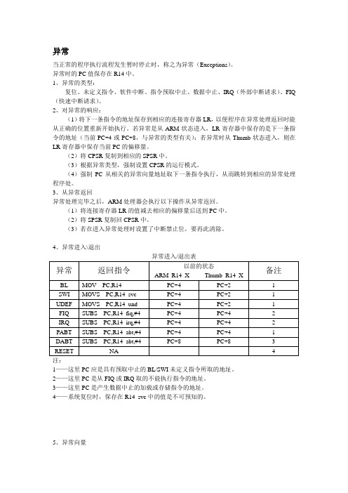
4、异常进入\退出异常进入/退出表1——这里PC应是具有预取中止的BL/SWI未定义指令所取的地址。
2——这里PC是从FIQ或IRQ取的不能执行指令的地址。
3——这里PC是产生数据中止的加载或存储指令的地址。
4——系统复位时,保存在R14_svc中的值是不可预知的。
5、异常向量异常向量表当多个异常发生时,系统根据固定的优先级决定异常处理的次序。
异常优先级如下表。
异常优先级当系统运行时,异常可能会随时发生,为保证在ARM处理器发生异常时不会处于未知状态,在应用程序的设计中,首先要进行异常处理。
采用的方式是在异常向量表中的特定位置放置一条跳转指令,跳转到异常处理程序。
当ARM处理器发生异常时,程序计数器PC会被强制设置对应的异常向量,从而跳转到异常处理程序,当异常处理完成以后,返回到主程序继续执行。
Error MessagesF9001 Error internal function call.F9002 Error internal RTOS function callF9003 WatchdogF9004 Hardware trapF8000 Fatal hardware errorF8010 Autom. commutation: Max. motion range when moving back F8011 Commutation offset could not be determinedF8012 Autom. commutation: Max. motion rangeF8013 Automatic commutation: Current too lowF8014 Automatic commutation: OvercurrentF8015 Automatic commutation: TimeoutF8016 Automatic commutation: Iteration without resultF8017 Automatic commutation: Incorrect commutation adjustment F8018 Device overtemperature shutdownF8022 Enc. 1: Enc. signals incorr. (can be cleared in ph. 2) F8023 Error mechanical link of encoder or motor connectionF8025 Overvoltage in power sectionF8027 Safe torque off while drive enabledF8028 Overcurrent in power sectionF8030 Safe stop 1 while drive enabledF8042 Encoder 2 error: Signal amplitude incorrectF8057 Device overload shutdownF8060 Overcurrent in power sectionF8064 Interruption of motor phaseF8067 Synchronization PWM-Timer wrongF8069 +/-15Volt DC errorF8070 +24Volt DC errorF8076 Error in error angle loopF8078 Speed loop error.F8079 Velocity limit value exceededF8091 Power section defectiveF8100 Error when initializing the parameter handlingF8102 Error when initializing power sectionF8118 Invalid power section/firmware combinationF8120 Invalid control section/firmware combinationF8122 Control section defectiveF8129 Incorrect optional module firmwareF8130 Firmware of option 2 of safety technology defectiveF8133 Error when checking interrupting circuitsF8134 SBS: Fatal errorF8135 SMD: Velocity exceededF8140 Fatal CCD error.F8201 Safety command for basic initialization incorrectF8203 Safety technology configuration parameter invalidF8813 Connection error mains chokeF8830 Power section errorF8838 Overcurrent external braking resistorF7010 Safely-limited increment exceededF7011 Safely-monitored position, exceeded in pos. DirectionF7012 Safely-monitored position, exceeded in neg. DirectionF7013 Safely-limited speed exceededF7020 Safe maximum speed exceededF7021 Safely-limited position exceededF7030 Position window Safe stop 2 exceededF7031 Incorrect direction of motionF7040 Validation error parameterized - effective thresholdF7041 Actual position value validation errorF7042 Validation error of safe operation modeF7043 Error of output stage interlockF7050 Time for stopping process exceeded8.3.15 F7051 Safely-monitored deceleration exceeded (159)8.4 Travel Range Errors (F6xxx) (161)8.4.1 Behavior in the Case of Travel Range Errors (161)8.4.2 F6010 PLC Runtime Error (162)8.4.3 F6024 Maximum braking time exceeded (163)8.4.4 F6028 Position limit value exceeded (overflow) (164)8.4.5 F6029 Positive position limit exceeded (164)8.4.6 F6030 Negative position limit exceeded (165)8.4.7 F6034 Emergency-Stop (166)8.4.8 F6042 Both travel range limit switches activated (167)8.4.9 F6043 Positive travel range limit switch activated (167)8.4.10 F6044 Negative travel range limit switch activated (168)8.4.11 F6140 CCD slave error (emergency halt) (169)8.5 Interface Errors (F4xxx) (169)8.5.1 Behavior in the Case of Interface Errors (169)8.5.2 F4001 Sync telegram failure (170)8.5.3 F4002 RTD telegram failure (171)8.5.4 F4003 Invalid communication phase shutdown (172)8.5.5 F4004 Error during phase progression (172)8.5.6 F4005 Error during phase regression (173)8.5.7 F4006 Phase switching without ready signal (173)8.5.8 F4009 Bus failure (173)8.5.9 F4012 Incorrect I/O length (175)8.5.10 F4016 PLC double real-time channel failure (176)8.5.11 F4017 S-III: Incorrect sequence during phase switch (176)8.5.12 F4034 Emergency-Stop (177)8.5.13 F4140 CCD communication error (178)8.6 Non-Fatal Safety Technology Errors (F3xxx) (178)8.6.1 Behavior in the Case of Non-Fatal Safety Technology Errors (178)8.6.2 F3111 Refer. missing when selecting safety related end pos (179)8.6.3 F3112 Safe reference missing (179)8.6.4 F3115 Brake check time interval exceeded (181)Troubleshooting Guide | Rexroth IndraDrive Electric Drivesand ControlsI Bosch Rexroth AG VII/XXIITable of ContentsPage8.6.5 F3116 Nominal load torque of holding system exceeded (182)8.6.6 F3117 Actual position values validation error (182)8.6.7 F3122 SBS: System error (183)8.6.8 F3123 SBS: Brake check missing (184)8.6.9 F3130 Error when checking input signals (185)8.6.10 F3131 Error when checking acknowledgment signal (185)8.6.11 F3132 Error when checking diagnostic output signal (186)8.6.12 F3133 Error when checking interrupting circuits (187)8.6.13 F3134 Dynamization time interval incorrect (188)8.6.14 F3135 Dynamization pulse width incorrect (189)8.6.15 F3140 Safety parameters validation error (192)8.6.16 F3141 Selection validation error (192)8.6.17 F3142 Activation time of enabling control exceeded (193)8.6.18 F3143 Safety command for clearing errors incorrect (194)8.6.19 F3144 Incorrect safety configuration (195)8.6.20 F3145 Error when unlocking the safety door (196)8.6.21 F3146 System error channel 2 (197)8.6.22 F3147 System error channel 1 (198)8.6.23 F3150 Safety command for system start incorrect (199)8.6.24 F3151 Safety command for system halt incorrect (200)8.6.25 F3152 Incorrect backup of safety technology data (201)8.6.26 F3160 Communication error of safe communication (202)8.7 Non-Fatal Errors (F2xxx) (202)8.7.1 Behavior in the Case of Non-Fatal Errors (202)8.7.2 F2002 Encoder assignment not allowed for synchronization (203)8.7.3 F2003 Motion step skipped (203)8.7.4 F2004 Error in MotionProfile (204)8.7.5 F2005 Cam table invalid (205)8.7.6 F2006 MMC was removed (206)8.7.7 F2007 Switching to non-initialized operation mode (206)8.7.8 F2008 RL The motor type has changed (207)8.7.9 F2009 PL Load parameter default values (208)8.7.10 F2010 Error when initializing digital I/O (-> S-0-0423) (209)8.7.11 F2011 PLC - Error no. 1 (210)8.7.12 F2012 PLC - Error no. 2 (210)8.7.13 F2013 PLC - Error no. 3 (211)8.7.14 F2014 PLC - Error no. 4 (211)8.7.15 F2018 Device overtemperature shutdown (211)8.7.16 F2019 Motor overtemperature shutdown (212)8.7.17 F2021 Motor temperature monitor defective (213)8.7.18 F2022 Device temperature monitor defective (214)8.7.19 F2025 Drive not ready for control (214)8.7.20 F2026 Undervoltage in power section (215)8.7.21 F2027 Excessive oscillation in DC bus (216)8.7.22 F2028 Excessive deviation (216)8.7.23 F2031 Encoder 1 error: Signal amplitude incorrect (217)VIII/XXII Bosch Rexroth AG | Electric Drivesand ControlsRexroth IndraDrive | Troubleshooting GuideTable of ContentsPage8.7.24 F2032 Validation error during commutation fine adjustment (217)8.7.25 F2033 External power supply X10 error (218)8.7.26 F2036 Excessive position feedback difference (219)8.7.27 F2037 Excessive position command difference (220)8.7.28 F2039 Maximum acceleration exceeded (220)8.7.29 F2040 Device overtemperature 2 shutdown (221)8.7.30 F2042 Encoder 2: Encoder signals incorrect (222)8.7.31 F2043 Measuring encoder: Encoder signals incorrect (222)8.7.32 F2044 External power supply X15 error (223)8.7.33 F2048 Low battery voltage (224)8.7.34 F2050 Overflow of target position preset memory (225)8.7.35 F2051 No sequential block in target position preset memory (225)8.7.36 F2053 Incr. encoder emulator: Pulse frequency too high (226)8.7.37 F2054 Incr. encoder emulator: Hardware error (226)8.7.38 F2055 External power supply dig. I/O error (227)8.7.39 F2057 Target position out of travel range (227)8.7.40 F2058 Internal overflow by positioning input (228)8.7.41 F2059 Incorrect command value direction when positioning (229)8.7.42 F2063 Internal overflow master axis generator (230)8.7.43 F2064 Incorrect cmd value direction master axis generator (230)8.7.44 F2067 Synchronization to master communication incorrect (231)8.7.45 F2068 Brake error (231)8.7.46 F2069 Error when releasing the motor holding brake (232)8.7.47 F2074 Actual pos. value 1 outside absolute encoder window (232)8.7.48 F2075 Actual pos. value 2 outside absolute encoder window (233)8.7.49 F2076 Actual pos. value 3 outside absolute encoder window (234)8.7.50 F2077 Current measurement trim wrong (235)8.7.51 F2086 Error supply module (236)8.7.52 F2087 Module group communication error (236)8.7.53 F2100 Incorrect access to command value memory (237)8.7.54 F2101 It was impossible to address MMC (237)8.7.55 F2102 It was impossible to address I2C memory (238)8.7.56 F2103 It was impossible to address EnDat memory (238)8.7.57 F2104 Commutation offset invalid (239)8.7.58 F2105 It was impossible to address Hiperface memory (239)8.7.59 F2110 Error in non-cyclical data communic. of power section (240)8.7.60 F2120 MMC: Defective or missing, replace (240)8.7.61 F2121 MMC: Incorrect data or file, create correctly (241)8.7.62 F2122 MMC: Incorrect IBF file, correct it (241)8.7.63 F2123 Retain data backup impossible (242)8.7.64 F2124 MMC: Saving too slowly, replace (243)8.7.65 F2130 Error comfort control panel (243)8.7.66 F2140 CCD slave error (243)8.7.67 F2150 MLD motion function block error (244)8.7.68 F2174 Loss of motor encoder reference (244)8.7.69 F2175 Loss of optional encoder reference (245)Troubleshooting Guide | Rexroth IndraDrive Electric Drivesand Controls| Bosch Rexroth AG IX/XXIITable of ContentsPage8.7.70 F2176 Loss of measuring encoder reference (246)8.7.71 F2177 Modulo limitation error of motor encoder (246)8.7.72 F2178 Modulo limitation error of optional encoder (247)8.7.73 F2179 Modulo limitation error of measuring encoder (247)8.7.74 F2190 Incorrect Ethernet configuration (248)8.7.75 F2260 Command current limit shutoff (249)8.7.76 F2270 Analog input 1 or 2, wire break (249)8.7.77 F2802 PLL is not synchronized (250)8.7.78 F2814 Undervoltage in mains (250)8.7.79 F2815 Overvoltage in mains (251)8.7.80 F2816 Softstart fault power supply unit (251)8.7.81 F2817 Overvoltage in power section (251)8.7.82 F2818 Phase failure (252)8.7.83 F2819 Mains failure (253)8.7.84 F2820 Braking resistor overload (253)8.7.85 F2821 Error in control of braking resistor (254)8.7.86 F2825 Switch-on threshold braking resistor too low (255)8.7.87 F2833 Ground fault in motor line (255)8.7.88 F2834 Contactor control error (256)8.7.89 F2835 Mains contactor wiring error (256)8.7.90 F2836 DC bus balancing monitor error (257)8.7.91 F2837 Contactor monitoring error (257)8.7.92 F2840 Error supply shutdown (257)8.7.93 F2860 Overcurrent in mains-side power section (258)8.7.94 F2890 Invalid device code (259)8.7.95 F2891 Incorrect interrupt timing (259)8.7.96 F2892 Hardware variant not supported (259)8.8 SERCOS Error Codes / Error Messages of Serial Communication (259)9 Warnings (Exxxx) (263)9.1 Fatal Warnings (E8xxx) (263)9.1.1 Behavior in the Case of Fatal Warnings (263)9.1.2 E8025 Overvoltage in power section (263)9.1.3 E8026 Undervoltage in power section (264)9.1.4 E8027 Safe torque off while drive enabled (265)9.1.5 E8028 Overcurrent in power section (265)9.1.6 E8029 Positive position limit exceeded (266)9.1.7 E8030 Negative position limit exceeded (267)9.1.8 E8034 Emergency-Stop (268)9.1.9 E8040 Torque/force actual value limit active (268)9.1.10 E8041 Current limit active (269)9.1.11 E8042 Both travel range limit switches activated (269)9.1.12 E8043 Positive travel range limit switch activated (270)9.1.13 E8044 Negative travel range limit switch activated (271)9.1.14 E8055 Motor overload, current limit active (271)9.1.15 E8057 Device overload, current limit active (272)X/XXII Bosch Rexroth AG | Electric Drivesand ControlsRexroth IndraDrive | Troubleshooting GuideTable of ContentsPage9.1.16 E8058 Drive system not ready for operation (273)9.1.17 E8260 Torque/force command value limit active (273)9.1.18 E8802 PLL is not synchronized (274)9.1.19 E8814 Undervoltage in mains (275)9.1.20 E8815 Overvoltage in mains (275)9.1.21 E8818 Phase failure (276)9.1.22 E8819 Mains failure (276)9.2 Warnings of Category E4xxx (277)9.2.1 E4001 Double MST failure shutdown (277)9.2.2 E4002 Double MDT failure shutdown (278)9.2.3 E4005 No command value input via master communication (279)9.2.4 E4007 SERCOS III: Consumer connection failed (280)9.2.5 E4008 Invalid addressing command value data container A (280)9.2.6 E4009 Invalid addressing actual value data container A (281)9.2.7 E4010 Slave not scanned or address 0 (281)9.2.8 E4012 Maximum number of CCD slaves exceeded (282)9.2.9 E4013 Incorrect CCD addressing (282)9.2.10 E4014 Incorrect phase switch of CCD slaves (283)9.3 Possible Warnings When Operating Safety Technology (E3xxx) (283)9.3.1 Behavior in Case a Safety Technology Warning Occurs (283)9.3.2 E3100 Error when checking input signals (284)9.3.3 E3101 Error when checking acknowledgment signal (284)9.3.4 E3102 Actual position values validation error (285)9.3.5 E3103 Dynamization failed (285)9.3.6 E3104 Safety parameters validation error (286)9.3.7 E3105 Validation error of safe operation mode (286)9.3.8 E3106 System error safety technology (287)9.3.9 E3107 Safe reference missing (287)9.3.10 E3108 Safely-monitored deceleration exceeded (288)9.3.11 E3110 Time interval of forced dynamization exceeded (289)9.3.12 E3115 Prewarning, end of brake check time interval (289)9.3.13 E3116 Nominal load torque of holding system reached (290)9.4 Non-Fatal Warnings (E2xxx) (290)9.4.1 Behavior in Case a Non-Fatal Warning Occurs (290)9.4.2 E2010 Position control with encoder 2 not possible (291)9.4.3 E2011 PLC - Warning no. 1 (291)9.4.4 E2012 PLC - Warning no. 2 (291)9.4.5 E2013 PLC - Warning no. 3 (292)9.4.6 E2014 PLC - Warning no. 4 (292)9.4.7 E2021 Motor temperature outside of measuring range (292)9.4.8 E2026 Undervoltage in power section (293)9.4.9 E2040 Device overtemperature 2 prewarning (294)9.4.10 E2047 Interpolation velocity = 0 (294)9.4.11 E2048 Interpolation acceleration = 0 (295)9.4.12 E2049 Positioning velocity >= limit value (296)9.4.13 E2050 Device overtemp. Prewarning (297)Troubleshooting Guide | Rexroth IndraDrive Electric Drivesand Controls| Bosch Rexroth AG XI/XXIITable of ContentsPage9.4.14 E2051 Motor overtemp. prewarning (298)9.4.15 E2053 Target position out of travel range (298)9.4.16 E2054 Not homed (300)9.4.17 E2055 Feedrate override S-0-0108 = 0 (300)9.4.18 E2056 Torque limit = 0 (301)9.4.19 E2058 Selected positioning block has not been programmed (302)9.4.20 E2059 Velocity command value limit active (302)9.4.21 E2061 Device overload prewarning (303)9.4.22 E2063 Velocity command value > limit value (304)9.4.23 E2064 Target position out of num. range (304)9.4.24 E2069 Holding brake torque too low (305)9.4.25 E2070 Acceleration limit active (306)9.4.26 E2074 Encoder 1: Encoder signals disturbed (306)9.4.27 E2075 Encoder 2: Encoder signals disturbed (307)9.4.28 E2076 Measuring encoder: Encoder signals disturbed (308)9.4.29 E2077 Absolute encoder monitoring, motor encoder (encoder alarm) (308)9.4.30 E2078 Absolute encoder monitoring, opt. encoder (encoder alarm) (309)9.4.31 E2079 Absolute enc. monitoring, measuring encoder (encoder alarm) (309)9.4.32 E2086 Prewarning supply module overload (310)9.4.33 E2092 Internal synchronization defective (310)9.4.34 E2100 Positioning velocity of master axis generator too high (311)9.4.35 E2101 Acceleration of master axis generator is zero (312)9.4.36 E2140 CCD error at node (312)9.4.37 E2270 Analog input 1 or 2, wire break (312)9.4.38 E2802 HW control of braking resistor (313)9.4.39 E2810 Drive system not ready for operation (314)9.4.40 E2814 Undervoltage in mains (314)9.4.41 E2816 Undervoltage in power section (314)9.4.42 E2818 Phase failure (315)9.4.43 E2819 Mains failure (315)9.4.44 E2820 Braking resistor overload prewarning (316)9.4.45 E2829 Not ready for power on (316)。
一、Hard fault产生原因硬件方面常见原因:1.电源设计有错误,造成器件供电不稳;2.电源质量不好,文波,噪声过大;3.器件接地不良;4.对于带有Vcap引脚的器件,管脚处理不当;5.电路中有强干扰源,对器件造成干扰;软件方面常见原因:1.使用了空指针;2.对地址偏移量的计算有误;3.数组越界导致程序出错;4.动态内存使用不当,导致访问了已释放的内存地址;5.通过地址访问了已失效的局部变量;一般因为硬件造成Hard Fault错误的可能性较低,90%都是软件原因造成的。
所以遇到硬件中断错误,基本就是通过软件来排查二、排查问题使用到的工具:Jlink,Segger(Jlink上位机),Keil三、排查步骤1.使用keil生成map文件,生成lst文件。
Map文件是keil自动生成的,里面能标明每个函数、每个变量的位置。
他被放在工程路径下。
lst文件反映的是每一个函数,每一条指令的PC指针,在keil中需要调用USER命令生成:D:\Keil\ARM\ARMCC\bin\fromelf.exe -c --output ./project.lst ./obj/project.axfD:\Keil\ARM\ARMCC\bin\fromelf.exe表示的是fromelf.exe的路径;./obj/project.axf表示生成的axf文件位置,可能需要根据实际情况调整;2.保存出问题时候的RAM;出问题的时候调用别断电,接上Jlink,调用Segger里面的Jlink command来获取现场:a.先输入一个“USB”让Jlink接上设备,然后输入halt来停住内核;b.调用savebin ram.bin 0x20000000 0x2000将RAM中的内容全部保存下来;保存下来的东西被存在放Segger的安装目录中。
3.分析问题查看map文件找到栈的位置。
打开保存的bin文件,找到进入硬件中断前调用了哪些函数,在使用哪个变量,然后逐一分析。
加密系统调试_HCS12学习笔记(8)
最近搞了一下关于加密的调试,在此做个记录。
其实很简单,只是对#FF0F 进行操作一下就可以了,具体位操作详见
S12FTS256KV2.PDF,寄存器FESC。
在MAIN.C 的最后加上
const volatile unsigned char SecureReg @(0xFF0F)=0xFC;
即可,注意VOLATILE 字样,如果没有的话,可能被DUBUG 掉。
我对所有的程序进行了调试,一切正常,只有在涉及到FLASH 擦写时,程
序无法正常运行,或者把程序段放入FLASH 分页时无法正常运行。
查了N 多
资料,未果。
于是找了FREESCALE 的技术支持,交流过后发现,是我芯片型号的问题,
因为我的芯片的MASK 是1K79X,比较老的型号,所以确实在这个方面是有
问题的,如果换成了DT256 或者高版本的MASK,即可解决问题。
这里是1K79X 参错里的内容,描述了这个问题。
MUCts00603: FLASHProgram & erase blocked in normal single chip mode when secureDescriptionIn normal single chip mode, when security is enabled, it is not。