赛思通产品通用数据标准
- 格式:doc
- 大小:969.50 KB
- 文档页数:63
SONET指南-其它通用标准华为技术有限公司版权所有侵权必究SONET指南-其它通用标准文档密级:内部公开修订记录SONET指南-其它通用标准文档密级:内部公开目录1其它通用标准 (5)1.1物理和环境标准 (5)1.1.1设备运行环境 (5)1.1.2电磁兼容性 (5)1.1.3外置电缆 (5)1.2设备设计 (5)1.3文档和培训 (6)1.4安全 (6)1.4.1站点设备安全 (6)1.4.2光纤光缆安全 (7)1.5质量和可靠性 (7)1.5.1网络设备可靠性 (7)1.5.2光纤光缆质量和可靠性 (8)1.5.3器件可靠性保证 (8)1.6人为因素 (9)SONET指南-其它通用标准文档密级:内部公开关键词:段层线路层通道层性能监视摘要:无。
缩略语清单:DS1 Digital Signal Level 1(1.544Mbit/s)DS1A Digital Signal Level 1A (2.048Mbit/s)DS1C Digital Signal Level 1C (3.152Mbit/s)DS2 Digital Signal Level 2(6.312Mbit/s)DS3 Digital Signal Level 3(44.736Mbit/s)DS4NA Digital Signal Level 4A(139.264Mbit/s)OC-1 Optical Carrier Level 1(51.840Mbit/s)OC-192 Optical Carrier Level 192(10Gbit/s)LAPS Linear Automatic Protecting Switching(线路自动保护倒换)BER Bit Error Ratio(比特误码率)ADM Add/Drop Multiplexer(分插复用器)TM Termination Multiplexer(终端复用器)RGTR Regenarator(再生器)DCS Digital Cross-connect System(数字交叉系统)CB Channel Bank(通道汇流器)参考资料清单无。
赛思通产品通用数据标准(试行)技术中心二○一一年十一月目录一、前言 (1)1.目的 (1)2.基本内容 (1)3.通用数据集标准目录 (1)4.分类代码标准目录 (2)二、编制规范 (4)1.术语和定义 (4)2.内容结构 (4)3.数据元描述规则 (4)3.1.数据集元数据描述 (4)3.2.数据元标识符编码规则 (5)3.3.数据元值描述 (6)4.规范性引用文件 (11)三、SSTPB00.01公共基本数据集 (12)1.术语和缩略语 (12)2.数据集元数据 (13)3.数据元属性 (14)3.1单位001 (14)3.2角色002 (15)3.3权限003 (16)3.4用户004 (17)3.5菜单005 (18)3.6职员006 (19)3.7消息007 (20)3.8订阅008 (22)3.9编码009 (22)3.10日志010 (23)4.数据元值域代码表 (24)四、SSTPG01.01领域公共数据集 (30)1.术语和缩略语 (30)2.数据集元数据 (31)3.数据元属性 (31)3.1.成品油品001 (31)3.2.炼厂002 (33)3.3.油库003 (35)3.4.加油站004 (38)3.5.油库油罐005 (40)3.6.加油站油罐006 (41)3.7.销售分公司007 (42)3.8.批发客户008 (43)4. 数据元值域代码表 (48)一、前言1.目的本标准旨在为赛思通产品开发提供一套术语规范、定义明确、语义语境无歧义的基本数据集标准,以规范各产品的基本数据内容,指导赛思通产品开发和设计,实现各产品在收集、存储、发布、交换等应用中的一致性和可比性,保证各产品相互间的数据交换与共享。
2.基本内容根据赛思通产品定位和服务领域,通用数据的基本内容主要公共基础数据、石油石化领域公共数据、石油石化销售领域主数据、分类代码四部分组成。
●公共基础数据:反映任何产品系统必备的公共基础数据,与特定行业领域无关。


Datasheet2TruStability ® Board Mount Pressure SensorsThe TruStability ® Standard Accuracy Silicon Ceramic (SSC) Series is a piezoresistive silicon pressure sensor offering a ratiometric analog or digital output for reading pressure over the specified full scale pressure span and temperature range.The SSC Series is fully calibrated and temperature compensated for sensor offset, sensitivity, temperature effects, and non-linearity using an on-board Application Specific Integrated Circuit (ASIC). Calibrated output values for pressure are updated at approximately 1 kHz for analog and 2 kHz for digital.The SSC Series is calibrated over the temperature range of -20 °C to 85 °C [-4 °F to 185 °F]. The sensor is characterized for operation from a single power supply of either 3.3 Vdc or 5.0 Vdc.These sensors measure absolute, gage, or differential pressures. The absolute versions have an internal vacuum reference and an output value proportional to absolute pressure. Gage versions are referenced to atmospheric pressure and provide an output proportional to pressure variations from atmosphere. Differential versions allow measurement of pressure between two pressure ports.The TruStability ® pressure sensors are intended for use with non-corrosive, non-ionic gases, such as air and other dry gases. Available options extend the performance of these sensors to non-corrosive, non-ionic liquids for pressure ranges above 40 mbar | 4 kPa | 20 inH 2O.All products are designed and manufactured according to ISO 9001 standards.stability • accuracy • flexibility • small sizeWhat makes our sensors better?• Stability and reliability• Industry-leading accuracy of ±0.25 %FSS BFSL • Port and housing options simplify integration • Wide pressure range, from ±1.6 mbar to ±10 bar |±160 Pa to ±1 MPa | ±0.5 inH 2O to ±150 psi • Small package size• Extremely low power consumptionTable of ContentsFeatures and Benefits ..................3-5Potential Applications ....................6General Specifications .................7-8Analog Operating Specifications ...........9Digital Operating Specifications ...........10Transfer Function Limits .................11Total Error Band Values .................12Nomenclature and Order Guide ...........13Pressure Range Specifications±1.6 mbar to ±10 bar..................14 ±160 Pa to ±1 MPa ....................15 ±0.5 inH 2O to ±150 psi .................16Available Standard Configurations .......17-18Dimensional DrawingsDIP Packages .....................19-21 SMT Packages ...................21-24 SIP Packages .....................24-29Pinouts, PCB Layouts, Circuit Examples ....30TruStability ® Board Mount Pressure Sensors Portfolio Overview .....................31Additional Information. . . . . . . . . . . . . . . . . . .323 ProPrietAry Honeywell teCHnologyCombines high sensitivity with high overpressure and burst pressure while providing industry leading stability—performance factors that are difficult to achieve in the same product; this gives the customer more flexibility in sensor implementation and reduces the customer design requirements for protecting the sensor without sacrificing the ability to sense very small changes in pressure.ProteCteD By MUltiPle gloBAl PAtentS inDUStry-leADing long-terM StABilityEven after long-term use and thermal extremes, the sensor’s stability remains best in class:• Minimizes system calibration needs. • Improves system performance.• Helps support system uptime by minimizing the need to service or replace the sensor during its application life.totAl error BAnD (teB)Honeywell specifies TEB—the most comprehensive, clear, and meaningfulmeasurement—that provides the sensor’s true performance over a compensated range of -20 °C to 85 °C [-4 °F to 185 °F] (see Figure 1):• Minimizes individually testing and calibrating every sensor, decreasing manufacturing time and process costs. • Improves system accuracy.• Provides enhanced sensor interchangeability—there is minimal part-to-part variation in accuracy.Featuresand Benefits+Pressure Hysteresis+Pressure Non-RepeatabilityAll Possible ErrorsOffset++Full Scale Span+Thermal Effect on Offset+Thermal Effect on Span+Thermal HysteresisTotal Error BandAccuracy==Pressure Non-LinearityFigure 1. TEB Components for TruStability ® Board Mount Pressure SensorsFeatures and Benefits inDUStry-leADing ACCUrACyExtremely tight accuracy of ±0.25 %FSS BFSL (Full Scale Span Best Fit Straight Line) reduces software needs to correct system inaccuracies, minimizing system design time:• Avoids additional customer calibration.• Helps to improve system efficiency.• Often simplifies software development.HigH BUrSt PreSSUreS• Promotes system reliability and reduces potential system downtime.• Can simplify the design process.HigH working PreSSUre rAngeSAllows ultra-low pressure sensors to be used continuously well above the calibrated pressure range.inDUStry-leADing flexiBilityModular, flexible design with many package styles (with the same industry-leading stability), pressure ports, and options simplify integration into the device manufacturer’s application.wiDe vAriety of PreSSUre rAngeSFrom ±1.6 mbar to ±10 bar | ±160 Pa to ±1 MPa | ±0.5 inH2O to ±150 psi provide support for many unique applications.MeetS iPC/JeDeC J-StD-020D.1 MoiStUre SenSitivity level 1 reqUireMentS• Allows the customer to avoid the thermal and mechanical damage duringsolder reflow attachment and/or repair that lesser rated products would incur. • Allows unlimited floor life when stored as specified (<30 ºC/85 %RH),simplifying storage and reducing scrap.• Never requires lengthy bakes prior to reflow.• Stable and usable shortly after reflow process allows for lean manufacturing. oPtionAl internAl DiAgnoStiC fUnCtionS• May reduce the need for redundant sensors in the system.• Detects most internal failures including burst sensors.energy effiCientExtremely low power consumption (less than 10 mW, typ.):• Reduces system power requirements.• Enables extended battery life.• Optional sleep mode available upon special request.Features and Benefits oUtPUt: rAtioMetriC AnAlog; i2C- or SPi-CoMPAtiBle 14-Bit DigitAl oUtPUt (Min. 12-Bit SenSor reSolUtion) Accelerates performance through reduced conversion requirements and the convenience of direct interface to microprocessors.SMAll SizeMiniature 10 mm x 10 mm [0.39 in x 0.39 in] package is very small when compared to many board mount pressure sensors:• Occupies less area on the PCB.• Typically allows for easy placement on crowded PCBs or in small devices. reACH AnD roHS CoMPliAntliqUiD MeDiA oPtion• Provides robustness in environments with condensing humidity.• Compatible with a variety of non-ionic fluids.• Available for pressure ranges above 40 mbar | 4 kPa | 20 inH20.5MeDiCAl• Airflow MonitorS • AneStHeSiA MACHineS • BlooD AnAlySiS MACHineS • gAS flow inStrUMentAtion • kiDney DiAlySiS MACHineS • oxygen ConCentrAtorS • PneUMAtiC ControlS • reSPirAtory MACHineS • SleeP APneA eqUiPMent • ventilAtorS • SPiroMeterS • neBUlizerS• HoSPitAl rooM Air PreSSUreinDUStriAl• BAroMetry • flow CAliBrAtorS • gAS CHroMAtogrAPHy • gAS flow inStrUMentAtion • HvAC• life SCienCeS • PneUMAtiC Control• vAv (vAriABle Air volUMe) Control • CloggeD HvAC filter DeteCtion • HvAC trAnSMitterS • inDoor Air qUAlityPotential Applicationstable 1. Absolute Maximum ratings11Absolute maximum ratings are the extreme limits the device will withstand without damage.table 2. environmental Specifications1Life may vary depending on specific application in which the sensor is utilized.7CAUTIONPRODUCT DAMAGE FOR SENSORS WITH LIQUID MEDIA OPTION (ONLY AVAILABLE 60 MBAR | 6 KPA | 1 PSI AND ABOVE)• Ensure liquid media is applied to Port 1 only; Port 2 is not compatible with liquids.• Ensure liquid media contains no particulates. All TruStability® sensors are dead-ended devices. Particulates can accumulate inside the sensor, causing damage or affecting sensor output.• Recommend that the sensor be positioned with Port 1 facing downwards; any particulates in the system are less likely to enter and settle within the pressure sensor if it is in this position.• Ensure liquid media does not create a residue when dried; build-up inside the sensor may affect sensor output. Rinsing of a dead-ended sensor is difficult and has limited effectiveness for removing residue.• Ensure liquid media are compatible with wetted materials. Non-compatible liquid media will degrade sensor performance and may lead to sensor failure.Failure to comply with these instructions may result in product damage.table 4. Pressure types \table 3. wetted Materials 11Contact Honeywell Customer Service for detailed material information.table 5. Analog operating Specifications2Ratiometricity of the sensor (the ability of the device output to scale to the supply voltage) is achieved within the specified operating voltage.3The sensor is not reverse polarity protected. Incorrect application of supply voltage or ground to the wrong pin may cause electrical failure.4Operating temperature range: The temperature range over which the sensor will produce an output proportional to pressure.5Compensated temperature range: The temperature range over which the sensor will produce an output proportional to pressure within the specified performance limits.6Accuracy: The maximum deviation in output from a Best Fit Straight Line (BFSL) fitted to the output measured over the pressure range at 25 °C [77 °F]. Includes all errors due to pressure non-linearity, pressure hysteresis, and non-repeatability.7Orientation sensitivity: The maximum change in offset of the sensor due to a change in position or orientation relative to Earth’s gravitational field.8Full Scale Span (FSS): The algebraic difference between the output signal measured at the maximum (Pmax.) and minimum (Pmin.) limits of the pressure range. (See Figure 4 for ranges.)O.9Insignificant for pressure ranges above 40 mbar | 4 kPa | 20 inH2910table 7. Sensor output at Significant Percentages (digital versions only)table 6. Digital operating Specifications2Ratiometricity of the sensor (the ability of the device output to scale to the supply voltage) is achieved within the specified operating voltage.3The sensor is not reverse polarity protected. Incorrect application of supply voltage or ground to the wrong pin may cause electrical failure. 4Operating temperature range: The temperature range over which the sensor will produce an output proportional to pressure.5Compensated temperature range: The temperature range over which the sensor will produce an output proportional to pressure within the specified performance limits.6Accuracy: The maximum deviation in output from a Best Fit Straight Line (BFSL) fitted to the output measured over the pressure range at 25 °C [77 °F]. Includes all errors due to pressure non-linearity, pressure hysteresis, and non-repeatability.7Orientation sensitivity: The maximum change in offset of the sensor due to a change in position or orientation relative to Earth’s gravitational field.8Full Scale Span (FSS): The algebraic difference between the output signal measured at the maximum (Pmax.) and minimum (Pmin.) limits of the pressure range. (See Figure 4 for ranges.)9Insignificant for pressure ranges above 40 mbar | 4 kPa | 20 inH 2O.Transfer Function Limitsfigure 2. transfer function limits 1Analog versionsDigital versions0102030405060708090100123456789102% Total Error BandIdealP min.P max.Pressure (example unit)O u t p u t (%V s u p p l y )0.8 x Vsupply P max. – P min.Output (V) =x (Pressure applied – P min.) + 0.10 x Vsupply80%P max. – P min.Output (% of 214 counts) =x (Pressure applied – P min.) + 10%O u t p u t (% o f 214c o u n t s )010203040506070809010012345678910Pressure (example unit)2% Total Error BandIdealP min.P max.1Transfer Function “A” is shown. See Figure 4 for other available transfer function options.figure 3. total error Band values for full Scale Span Pressure rangesTotal Error Band ValuesGageDifferential.6 kPa 60 mbar | 6 kPa22222figure 4. nomenclature and order guideNomenclature and Order GuideFor example, SSCDNNN150PGAA3 de nes an SSC Series T ruStability ® Pressure Sensor, DIP package, NN pressure port, no special options,150 psi gage pressure range, analog output type, 10% to 90% of Vsupply transfer function, 3.3 Vdc supply voltage .1The transfer function limits define the output of the sensor at a given pressure input. By specifying Pmin. and Pmax., the output at Pmin. and Pmax., the complete transfer function Of the sensor is defined. See the graphical representations of the transfer function in the product datasheet, FIgure 2. For other available transfer functions contact Honeywell Customer Service. 2SPI output function is not avilable in SIP package.3Custom pressure ranges are available. Contact Honeywell Customer Service for more information.1The transfer function limits define the output of the sensor at a given pressure input. By specifying Pmin. and Pmax., the output at Pmin. and Pmax., the complete transfer function of the sensor is defined. See the graphical representations of the transfer function in Figure 2. For other available transfer functions contact Honeywell Customer Service. 2SPI output function is not available in SIP package.3table 8. Pressure range Specifications for ±1.6 mbar to ±10 barlimits (Pmin. to Pmax.) in which case the sensor may not provide a valid output until presssure is returned to within the operating pressure range. Tested to 1 million cycles, minimum.2Overpressure: The maximum pressure which may safely be applied to the product for it to remain in specification once pressure is returned to the operating pressure range. Exposure to higher pressures may cause permanent damage to the product. Unless otherwise specified this applies to all available pressure ports at any temperature with the operating temperature range.3Burst pressure: The maximum pressure that may be applied to any port of the product without causing escape of pressure media. Product should not be expected to function after exposure to any pressure beyond the burst pressure.4Common mode pressure: The maximum pressure that can be applied simultaneously to both ports of a differential pressure sensor without causing changes in specified performance.5Total Error Band: The maximum deviation from the ideal transfer function over the entire compensated temperature and pressure range. Includes all errors due to offset, full scalespan, pressure non-linearity, pressure hysteresis, repeatability, thermal effect on offset, thermal effect on span, and thermal hysteresis (see Figure 1).table 9. Pressure range Specifications for ±160 Pa to ±1 MPalimits (Pmin. to Pmax.) in which case the sensor may not provide a valid output until presssure is returned to within the operating pressure range. Tested to 1 million cycles, minimum.2Overpressure: The maximum pressure which may safely be applied to the product for it to remain in specification once pressure is returned to the operating pressure range. Exposure to higher pressures may cause permanent damage to the product. Unless otherwise specified this applies to all available pressure ports at any temperature with the operating temperature range.3Burst pressure: The maximum pressure that may be applied to any port of the product without causing escape of pressure media. Product should not be expected to function after exposure to any pressure beyond the burst pressure.4Common mode pressure: The maximum pressure that can be applied simultaneously to both ports of a differential pressure sensor without causing changes in specified performance.5Total Error Band: The maximum deviation from the ideal transfer function over the entire compensated temperature and pressure range. Includes all errors due to offset, full scalespan, pressure non-linearity, pressure hysteresis, repeatability, thermal effect on offset, thermal effect on span, and thermal hysteresis (see Figure 1).Specifications±0.5 inH 2O to ±150 psitable 10. Pressure range Specifications for 0.5 inH o to 150 psi Pmax.) in which case the sensor may not provide a valid output until pressure is returned to within the operating pressure range. Tested to 1 million cycles, minimum.2Overpressure: The maximum pressure which may safely be applied to the product for it to remain in specification once pressure is returned to the operating pressure range. Exposure to higher pressures may cause permanent damage to the product. Unless otherwise specified this applies to all available pressure ports at any temperature with the operating temperature range.3Burst pressure: The maximum pressure that may be applied to any port of the product without causing escape of pressure media. Product should not be expected to function after exposure to any pressure beyond the burst pressure.4Common mode pressure: The maximum pressure that can be applied simultaneously to both ports of a differential pressure sensor without causing changes in specified performance.5Total Error Band: The maximum deviation from the ideal transfer function over the entire compensated temperature and pressure range. Includes all errors due to offset, full scale span, pressure non-linearity, pressure hysteresis, repeatability, thermal effect on offset, thermal effect on span, and thermal hysteresis6Total Error Band after Auto-Zero: The maximum deviation from the ideal transfer function over the entire compensated pressure range at a constant temperature and supply voltage for a minimum of 24 hours after an auto-zero operation. Includes all errors due to full scale span, pressure non-linearity, pressure hysteresis, and thermal effect on span.figure 5. All Available Standard Configurations (Dimensional drawings on pages noted below.)page 24figure 5. All Available Standard Configurations (Continued; dimensional drawings on pages noted below.)——page 29figure 6. DiP Package Dimensional Drawings (continued)DIP and SMT PackagesSMT and SIP Packagesfigure 8. SiP Package Dimensional Drawings (continued)opposite sidesfigure 8. SiP Package Dimensional Drawings (continued)radial barbed ports, same sidePinouts, PCB Pad Layout table 11. Pinouts for DiP and SMt Packagestable 12. Pinouts for SiP Packagesfigure 9. recommended PCB Pad layoutsTruStability® Board Mount Pressure Sensors Portfolio Overviewtable 13. truStability® Board Mount Pressure Sensors Portfolio overview31ADDitionAl inforMAtionThe following associated literature is available at : • Product line guide • Product range guide • Product nomenclature tree • Installation instructions • Application information • Technical notes- I 2C Communications with Honeywell Digital Output Pressure Sensors- SPI Communications with Honeywell Digital OutputPressure SensorswArrAnty/reMeDyHoneywell warrants goods of its manufacture as being free of defective materials and faulty workmanship. Honeywell’s standard product warranty applies unless agreed to otherwise by Honeywell in writing; please refer to your order acknowledgement or consult your local sales office for specific warranty details. If warranted goods are returned to Honeywell during the period of coverage, Honeywell will repair or replace, at its option, without charge those items it finds defective. the foregoing is buyer’s sole remedy and is in lieu of all other warranties, expressed or implied, including those of merchantability and fitness for a particular purpose. in no event shall Honeywell be liable for consequential, special, or indirect damages.While we provide application assistance personally, through our literature and the Honeywell website, it is up to the customer to determine the suitability of the product in the application.Specifications may change without notice. The information we supply is believed to be accurate and reliable as of this printing. However, we assume no responsibility for its use.Sales and ServiceHoneywell serves its customers through a worldwide network of sales offices, representatives and distributors. For application assistance, current specifications, pricing or name of the nearest Authorized Distributor, contact your local sales office or email us at*********************. Visit us on the Web at Phone and Fax:Asia Pacific +65 6355-2828+65 6445-3033 Fax Europe +44 (0) 1698 481481+44 (0) 1698 481676 Fax Latin America +1-305-805-8188+1-305-883-8257 Fax USA/Canada +1-800-537-6945+1-815-235-6847+1-815-235-6545 FaxSensing and ControlHoneywell1985 Douglas Drive NorthGolden Valley, MN 55422 50099533-A-EN GLOAugust 2014© 2014 Honeywell International Inc. All rights reserved.。
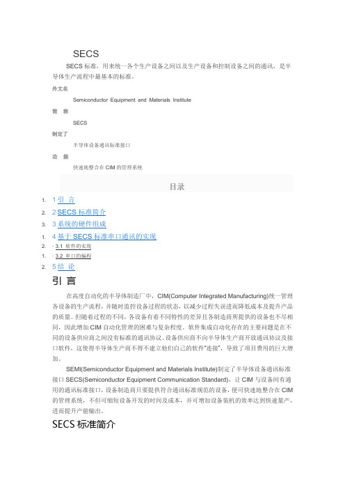
SECSSECS标准,用来统一各个生产设备之间以及生产设备和控制设备之间的通讯,是半导体生产流程中最基本的标准。
外文名Semiconductor Equipment and Materials Institute简称SECS制定了半导体设备通讯标准接口功能快速地整合在CIM的管理系统目录1. 1引言2. 2SECS标准简介3. 3系统的硬件组成1. 4基于SECS标准串口通讯的实现2. ▪3.1 软件的实现1. ▪ 3.2 串口的编程2. 5结论引言在高度自动化的半导体制造厂中,CIM(Computer Integrated Manufacturing)统一管理各设备的生产流程,并随时监控设备过程的状态,以减少过程失误进而降低成本及提升产品的质量。
但随着过程的不同,各设备有着不同特性的差异且各制造商所提供的设备也不尽相同,因此增加CIM自动化管理的困难与复杂程度。
软件集成自动化存在的主要问题是在不同的设备供应商之间没有标准的通讯协议。
设备供应商不向半导体生产商开放通讯协议及接口软件,这使得半导体生产商不得不建立他们自己的软件“连接”,导致了项目费用的巨大增加。
SEMI(Semiconductor Equipment and Materials Institute)制定了半导体设备通讯标准接口SECS(Semiconductor Equipment Communication Standard),让CIM与设备间有通用的通讯标准接口,设备制造商只要提供符合通讯标准规范的设备,便可快速地整合在CIM 的管理系统,不但可缩短设备开发的时间及成本,并可增加设备装机的效率达到快速量产,进而提升产能输出。
SECS标准简介系统,用来给更高层的管理人员提供管理上的方便。
图2 系统结构组成框图1.等待模块。
在此状态下,程序处于后台运行,直到接收到以下两种请求之一:①如果主机收到来自设备的一个ENQ信号(信号的意义见图3,以下同),则回送一个EOT信号给设备,同时自己转入接收状态;②如果设备收到发送命令,作如下处理:图3 握手建立的时序图a.向主机发送一个ENQ信号,然后不断侦听是否有来自主机的EOT信号。

SE965是一种二维条码扫描器模块,属于赛米康公司的产品,可以读取包括QR Code 在内的多种二维和一维条码。
SE965标准范围通常指该模块的标准读取能力范围,即可识别的最小和最大读取距离、角度、深度等。
具体范围可能因具体型号和产品规格而异,一般包括以下几个方面:
1. 读取距离:指该模块能够从何种距离内精确地读取条码信息,标准范围可能包括最大和最小读取距离。
2. 读取角度:指该扫描器能够以何种角度读取条码信息,标准范围可能包括水平角度范围、垂直角度范围、偏转角度范围等。
3. 读取深度:指该模块能够识别何种深度内的条码信息,标准范围可能包括最大和最小读取深度。
4. 支持的条码类型:指该模块能够识别哪些二维和一维条码类型,标准范围可能包括QR Code、PDF417、Data Matrix、Code39、Code128 等。
需要注意的是,具体的SE965标准范围可能因不同的应用场
景、环境和配置而有所不同。
如果您需要了解某个特定型号或配置的SE965的标准范围,请参考相关的数据手册或咨询赛米康公司或其授权的代理商或合作伙伴。
gmsl1 s参数测试标准
在汽车行业中,GMSL1 S参数测试标准是一项非常重要的技术规范。
GMSL1 S是指一种数字串行链路技术,它被广泛应用于汽车摄像头和传感器系统中。
这项技术标准的测试是为了确保汽车电子系统在各种复杂环境下的稳定性和可靠性。
GMSL1 S参数测试标准涉及到对串行链路的性能进行全面的评估,包括数据传输速率、抗干扰能力、信号完整性等方面的测试。
这些测试可以帮助汽车制造商和供应商确保他们的产品符合行业标准,并且能够在实际道路条件下可靠地运行。
在测试过程中,需要对GMSL1 S参数进行严格的测试,包括对数据传输速率的测量、抗干扰能力的评估、信号完整性的分析等。
这些测试可以通过使用专业的测试设备和仪器来完成,以确保测试结果的准确性和可靠性。
通过进行GMSL1 S参数测试,汽车制造商和供应商可以及时发现和解决潜在的问题,确保他们的产品能够满足市场需求,并且能够在各种复杂环境下可靠地运行。
这项技术标准的测试对于汽车行
业的发展和进步具有重要意义,可以帮助提升汽车电子系统的性能和可靠性,为驾驶员提供更加安全和舒适的驾驶体验。
研究数据、分析、结论、观点和本文的其他内容仅仅是作者的产品。
无论是汽车工程师协会(SAE)还是美国汽车研究委员会(USCAR)都不会出具任何证明某些产品符合基本要求的证书,也不会对本文内容的准确性和适用性作任何介绍.确定本文内容是否适用于自己的目的,完全是本文用户责任。
版权 2004, USCAR 美国印刷版权所有有关本文件的问题:(724) 772—8545 传真 (724)776—0243要订购文件: (724) 776—4970 传真(724) 776—0790图5.1。
5:A-方法1 毫伏导线附件也许可能发生这样的情况:被连接的电气部件或设备本身不能承受与它们所连接的连接器能够承受的试验。
在这种情况下,必须获取设备的连接器插座(容器)部分的样品。
然后执行试验需要的连接并进行密封。
为了测试对插端的完整性,设备中的漏洞需要密封。
这样的对设备的修改是适当的,但必须形成文件体现在测试报告中。
在任何情况下如果发生偏离正常试验性能规格的情况,应当向授权人咨询并且必须得到他的认可。
5。
1.6 端子样品准备用来试验的端子是指用推荐的制造工具机械压接好导线的端子。
根据各自的端子类型和线径规格,压接尺寸物理特性和机械拉脱力必须在规定的容许公差范围内。
在单独的试验程序中,如果没有其他特殊说明,导线的导体部分和绝缘体部分都要压接。
如果适用,使用适当的电线密封件。
按照制造商推荐的装配标准装配绝缘替代类型的端子.当试验具有对插端的端板类型的连接器时,只需准备插座连接器样品(参考5。
1.5部分)。
记录具有代表性的每一批端子样品的压接高度和压接宽度(不包括绝缘替代类型的端子),并且为了跟踪和后期验证的需要对样品进行编号.根据SAE/USCAR-21:电线到端子的电气压接性能标准,端子的压接状况应该被试验和验证。
表5.1.9。
3 电路监控的通用方式说明:如果有实际经验,建议用“X"方式(所示孔位)图表5。
1.9。
OEKO-TEX® - Oeko-Tex®国际环保纺织协会OEKO-TEX® - International Association forResearch and Testing in the Field of Tex-tile EcologyOEKO-TEX® Standard 100(Chinese Simplified / English)授权使用Oeko - Tex ® Standard 100标签的一般和特殊条款General and special conditions for the authorisation to use the Oeko-Tex ® Standard 100 mark 内容Contents1目的1Purpose 2适用范围2Applicability3条款及定义3Terms and definitions 3.1有害物质3.1Harmful substances3.2OEKO-TEX ® Standard 100 标签 3.2OEKO-TEX ® Standard 100 mark 3.3生产商 3.3Manufacturer 3.4销售商 3.4Distributor3.5产品名称 3.5Designation of product 3.6产品组合 3.6Article group 3.7产品类别 3.7Product classes3.8活性化学产品 3.8Active chemical products 4条款4Conditions4.1产品特定要求4.1Product specific requirements4.2使用生物活性产品的要求 4.2Requirements regarding the use of biological ac-tive products4.3使用阻燃产品的要求 4.3Requirements regarding the use of flame retard-ant products 4.4申请 4.4Application4.5样品材料 4.5Sample material4.6承诺声明 4.6Declaration of commitment 4.7检测4.7Testing4.8质量控制 4.8Quality control 4.9质量保证 4.9Quality assurance 4.10符合性 4.10Conformity 5标签5Marking5.1给予授权 5.1Granting of authorisation 5.2授权限制 5.2Limit of authorisation5.3授权撤销 5.3Withdrawal of authorisation 5.4标签类型 5.4Type of marking A1地址A1Adresses A2标签A2MarkA3包装指引A3Packing instructions A4限量值A4Limit valuesA5个别物质A5Individual substances版本说明Impressum编辑Editor:OEKO-TEX®国际环保纺织协会International Association for Research and Testing inthe Field of Textile Ecology (OEKO-TEX®) Gotthardstr. 61Gotthardstr. 61P.O. Box 2156P.O. Box 2156CH-8027 Zürich (Switzerland)CH-8027 Zurich (Switzerland)出版Place of origin:Zurich (Switzerland)Zurich (Switzerland)印刷:Printing:自设复印系统Own copy system版本: 01/2013Edition: 01/2013€ 40.- / CHF 70.- / SEK 390.- / DKK 330.- / NOK 360.- / £ 34.- / Ft 6’100.-售价 / selling price(OEKO-TEX ®)出版的规范性文件,该协会的成员机构在附录一中列出。
C.4.10除逸散性排放以外的试验的验收标准表C.5和C.6提供了在不同温度下可接受的阀座泄漏量。
表C.5 在环境温度(高于-20°C)和提高温度下进行泄漏测试的验收标准表C.6低温或超低温阀座泄漏测试的验收标准(-29°C至-196°C)注意:1.制造商应计算泄漏接受水平,并在相关概要表的相应部分说明。
2.金属阀座或金属石墨层压阀座蝶阀在优选流动方向上的最大允许阀座泄漏率应符合ISO 5208速率B.这些蝶阀在非优选流动方向上的最大允许阀座泄漏率应符合ISO 5208速率C.3.如果阀门符合ISO 5208中的阀座泄漏率A或B或符合IEC 60534-4的V级或VI级阀门,则认为阀门为TSO。
4.当与填塞器,阀座密封件和阀杆相关的部件在设计和尺寸上相同时,可以使用减小的孔(或文丘里管型)测试阀来限定较小的标称尺寸的全孔(或规则图案)阀。
在这种情况下,允许的平均泄漏率是适用于全孔(或规则型)阀的那些。
5.金属阀止回阀的最大允许阀座泄漏应符合适用的产品标准或ISO 5208 E级,以较低者为准。
表C.5中列出的费率涵盖了这一要求。
止回阀的目的是在过程变化或系统故障的情况下防止不希望的反向流动。
止回阀不是隔离阀,因此不需要非常紧密的阀座泄漏率。
C.4.11逃逸排放测试的验收标准所有温度下的逃逸排放测试的验收标准应符合表C.7和C.8的规定。
表C.7阀杆密封逸散排放泄漏的验收标准表 c.8 阀体/阀盖密封逸散排放泄漏的验收标准表C.7给出了每个阀杆周长或直径的允许泄漏率,而表C.9给出了不同阀杆尺寸的允许泄漏率。
表C.9不同阀杆尺寸的逸散排放泄漏率C.4.12最短测试持续时间最短试验时间应符合表C.10和C.11的规定。
表C.10 阀体/外壳逃逸排放测试的最短测试持续时间Valve sizes 阀门尺寸pressure class 压力等级Minimum test duration (minutes) 最小测试持续时间(分钟)The measurement is complete when a stable reading is reached 达到稳定读数时,测量完成表C.11闭孔密封性试验的最短试验时间Minimum duration for each step 每个步骤的最短持续时间C.4.15最大允许工作扭矩值基于360 N的力,表C.12中显示了不同轮辋尺寸的最大允许扭矩值。
赛思通产品通用数据标准(试行)技术中心二○一一年十一月目录一、前言 (1)1.目的 (1)2.基本内容 (1)3.通用数据集标准目录 (1)4.分类代码标准目录 (2)二、编制规范 (4)1.术语和定义 (4)2.内容结构 (4)3.数据元描述规则 (4)3.1.数据集元数据描述 (4)3.2.数据元标识符编码规则 (5)3.3.数据元值描述 (6)4.规范性引用文件 (11)三、SSTPB00.01公共基本数据集 (12)1.术语和缩略语 (12)2.数据集元数据 (13)3.数据元属性 (14)3.1单位001 (14)3.2角色002 (15)3.3权限003 (16)3.4用户004 (17)3.5菜单005 (18)3.6职员006 (19)3.7消息007 (20)3.8订阅008 (22)3.9编码009 (22)3.10日志010 (23)4.数据元值域代码表 (24)四、SSTPG01.01领域公共数据集 (30)1.术语和缩略语 (30)2.数据集元数据 (31)3.数据元属性 (31)3.1.成品油品001 (31)3.2.炼厂002 (33)3.3.油库003 (35)3.4.加油站004 (38)3.5.油库油罐005 (40)3.6.加油站油罐006 (41)3.7.销售分公司007 (42)3.8.批发客户008 (43)4. 数据元值域代码表 (48)一、前言1.目的本标准旨在为赛思通产品开发提供一套术语规范、定义明确、语义语境无歧义的基本数据集标准,以规范各产品的基本数据内容,指导赛思通产品开发和设计,实现各产品在收集、存储、发布、交换等应用中的一致性和可比性,保证各产品相互间的数据交换与共享。
2.基本内容根据赛思通产品定位和服务领域,通用数据的基本内容主要公共基础数据、石油石化领域公共数据、石油石化销售领域主数据、分类代码四部分组成。
●公共基础数据:反映任何产品系统必备的公共基础数据,与特定行业领域无关。
主要有:用户、权限、角色等。
●石油石化领域公共数据:反映成品油销售领域公共数据,该信息可能跨越两个或两个以上的产品系统。
主要有:油品、加油站、油库等。
●石油石化销售领域主数据:反映石油石化销售某个特定子领域的数据,如小额配送、二次配送、加油站零售等。
●分类代码:反映数据元的结构层次和组成,对数据元的分类与编码,如销售方式、支付方式等。
3.通用数据集标准目录根据平台目前开发状况,结合已开发产品情况,目前已整理出公共基础数据集、石油石化领域公共数据集两个类目,后续可根据实际情况进行完善补充。
表1列出了赛思通产品通用数据集标准目录。
如:《采购领域数据集》的数据集标识符为“SSTPG04.01”,表示该数据集标准属于通用数据集中的一级类目“石油石化(PG)”下的二级类目“市场销售(04)”,数据集顺序号为“01”。
表1. 赛思通产品通用数据集标准目录4.分类代码标准目录数据元之间存在着一定的层次结构关系。
从信息学角度对数据元进行科学分类与编码,目的是为产品中所有信息(数据元),建立一个统一的、标准化的信息分类框架,使得不同的信息(数据元)根据其不同的特性,能够分别定位和存储在相应的层级结构中,方便利用者的快速理解和共享。
赛思通产品通用数据元分类代码标准见表2。
表2. 数据元分类代码标准二、编制规范1.术语和定义公共数据 Public Base各产品与特定业务领域无关的公共基础数据,这些数据为每个产品都必须具备,是不同业务领域之间进行无歧义信息交换和数据共享的基础。
石油石化 Petro Gas针对石油石化行业领域的数据集,这些数据为石油石化行业所特有,带有专业性色彩,为面向石油石化应用时所需。
其他通用术语文档中使用到的其他通用的表示术语归纳如下:表3. 通用表示类术语2.内容结构每个数据集要求至少由以下内容部分构成:●术语和缩略语●数据集元数据:对数据集的描述●数据元属性●数据元值域代码表3.数据元描述规则3.1.数据集元数据描述数据集的数据元采用表(4)中的5类14项数据元属性进行描述。
表4. 数据元属性列表3.2.数据元标识符编码规则标识符指数据元在某特定数据集中的唯一标识代码。
标识符采用长度15位的字母数字混合码+版本标识号组成,含小数点3位。
结构见图(1)。
□□□□□□□ . □□ . □□□. □□□. VI数据元版本号数据元顺序号数据元小类编码数据集分类编码图1 标识符结构图(1)中:——数据集分类编码(DCC):用8位字母数字混合码表示,编码规则为一级类目+二级类目+数据集顺序号组成。
——数据元顺序号:用3位数字表示,代表数据元在某特定数据集中的序号,从001开始顺序编码。
数据元顺序号与数据集分类编码之间加“.”区分。
——数据元版本号VI:结构由4部分组成,为“V”+“m..m”+“.”+“n..n”。
其中,“m..m”和“n..n”为阿拉伯数字构成,在数学上应是具有意义的正整数。
“m..m”表示主版本号,“n..n”表示次版本号。
如果数据元更新前后可以进行有效的数据交换,则更新后主版本号不变,次版本号等于当前次版本号加1;如果数据元更新前后无法进行有效的数据交换,则更新后主版本号等于当前主版本号加1,次版本号归0。
3.3.数据元值描述1)、数据类型“数据元值的数据类型”的描述规则见表(5)。
表5. 数据元值的数据类型描述规则2)、表示格式“数据元值的表示格式”中,字符含义描述规则见表(6),字符长度描述规则见表(7)。
表6. 数据元值的表示格式中字符含义描述规则表7. 数据元值的表示格式中字符长度描述规则数据元值的表示格式示例:a)字符型(S)AN18 固定长度为18个字符(字母或(和)数字)长度的字符。
A..100 可变长度,最大为100个字符(字母)长度的字符。
AN..100 可变长度,最大为100个字符(字母或(和)数字)长度的字符。
N2 固定长度为2个字符(数字)长度的字符。
AN..40X3 最多3行,每行最大长度为40个字符(字母或(和)数字)长度的字符。
b)布尔型(L)L(1)或L(T) 表示取值为真;L(0)或L(F) 表示取值为假;c)数值型(N)N3 固定长度为3位数字。
N..3 最大长度为3位数字。
N2..4 最小长度为2位,最大长度为4位数字。
N5,1 最大长度为5位的十进制小数格式(包括小数点),小数点后保留1位数字。
N5..7,1 最小长度为5位,最大长度为7位的十进制小数格式(包括小数点),小数点后保留1位数字。
N5..8,..2 最小长度为5位,最大长度为8位的十进制小数格式(包括小数点),小数点后保留最多2位数字。
d)日期型(D)D8 采用YYYYMMDD格式(8位定长)表示年月日。
如1998年1月8日,应表示为19980108。
e)日期时间型(DT)DT15 采用YYYYMMDDThhmmss格式(15位定长)表示年月日时分秒。
f)时间型(T)T6 采用hhmmss格式(6位定长)表示时分秒。
g)二进制(BY)BY-JPEG BY后加具体的媒体格式表示,表示该数据是一个JPEG格式文件。
3)、数据元允许值值域是一组数据元允许值的集合。
一个允许值是某个值和该值的含义(值含义)的组合。
值域有两种子类:(1)可枚举值域:由允许值列表规定的值域,每个允许值的值和值含义均应成对表示。
其中:——可选值较少的(如3个或以下),可在“数据元允许值”属性列中直接描述(穷举)。
——可选值较多的(如3个以上),可在“数据元允许值”属性列中写出值域代码表的名称。
属引用的标准的,还须写出引用的具体部分。
(2)不可枚举值域:由描述规定的值域。
须准确描述属于该值域的允许值。
可枚举值域代码表格式如下:值域代码表名称其中:a)值域代码表名称:用“表号”+“表名”表示。
b)值的描述规则:——值域代码表中的值(代码值)一般采用层次结构的数字型代码,部分引用国标的值采用字母型代码,如世界各国和地区代码。
应预留一定的代码值空间以满足扩充要求。
——数字型代码不得使用“0”作为代码(引用的标准除外)。
——一般用“1”表示“是”或“异常”,“2”表示“非”或“正常”。
——代码的最高位数(如:9,99等),用于表示无法归类的“其他”。
——在同一层次中使用等长代码,不足总位数的代码值应在值前加“0”补齐。
c)表号的编码规则:值域代码表的表号编码结构为:CV +代码标识符。
采用总长度9位的字母数字混合码。
其中:——CV:表示代码。
——代码标识符:参考数据标识符(DI)编码规则,采用长度7位的数字码,含小数点1位。
按领域代码、分类代码、顺序号从左向右顺序排列。
结构见图(3)。
□□□□ . □□顺序号分类代码领域代码图3 代码标识符结构图(3)中:——领域代码:用2位字母表示,即所属数据集的一级分类目录代码号。
——分类代码:用2位数字表示,数字大小无含义;从01开始顺序编码。
——顺序号:用2位数字表示,代表某一小类下的值域代码表序号,数字大小无含义;从01开始顺序编码。
顺序号与小类代码之间加“.”区分。
4).常用计量单位符号表示计量单位符号是使数值型数据元产生实际意义的计算和度量单位的符号。
没有符号的可使用规范的中文字词。
常用计量单位符号见表(8),法定构成十进倍数和分数单位的词头见表(9)。
表8. 常用计量单位表9. 法定构成十进倍数和分数单位的词头义;从01开始顺序编码。
顺序号与二级类目代码之间加“.”区分。
4.规范性引用文件本标准引用参考了下列文件中的条款:GB/T 7408-2005 数据元和交换格式信息交换日期和时间表示法GB/T 17295-1998 国际贸易用计量单位代码WS/T 305-2009 卫生信息数据集元数据规范三、SSTPB00.01公共基本数据集1.术语和缩略语石油石化 Petro Gas针对石油石化行业领域的数据集,这些数据为石油石化行业所特有,带有专业性色彩,为面向石油石化应用时所需。
单位 Department对现实世界组织机构的抽象,泛指企业、政府及其他非盈利机构,为软件系统的主要使用组织、所有者;组织机构通常是多级树形结构,包含若干子机构、部门。
角色 Role对现实世界组织机构中工作岗位的抽象,亦可认为是系统使用者的抽象映射,一个用户可承担多个角色,一个角色也可由若干用户承担;复杂的角色建模中角色通常为多级树形结构,可以继承和再次授权,本规范为简化,视其为平行结构。
权限 Right对现实世界人在组织机构中权利和义务的抽象,在软件系统中映射为对系统资源的占有、使用和分配权利,本规范中权限为平行结构。
用户 User对现实世界组织机构中成员的抽象,为软件系统的使用者,现实世界一个或多个人可映射软件系统中一个或多个帐号。