PT1301_DS_EN3.5-英文版
- 格式:pdf
- 大小:437.05 KB
- 文档页数:10


1 概述DTSD341/DSSD331(配置号为ME2(SN))三相电子式多功效电能表是一款符合DL/T 614《多功效电能表》标准0.2S 级和0.5S 级三相电子式多功效电能表。
其关键特点为计量信号为数字流输入、高速数据处理能力、电源采取双路外接电源供电。
适适用于采取IEC61850-9-1/2标准协议电能计量体系。
DTSD341/DSSD331(配置号为ME2(SN))三相电子式多功效电能表研发和生产符合以下标准: GB/T 15543《电能质量 三相电压许可不平衡度》 GB/T 17882《2级和3级静止式交流无功电能表》 GB/T 17883《0.2S 级和0.5S 级静止式交流有功电能表》 DL/T 614 《多功效电能表》DL/T 645 《多功效电能表通信规约》(威胜企业对此协议有扩展) IEC61850-9-2 《数字化变电站通信规约》 1.1 工作原理DSSD331/DTSD341(配置号为ME2(SN))三相电子式多功效电能表是一款遵照IEC61850-9-2LE (数字化变电站内通信规约)协议全新数字接口式多功效电能表,采取当今世界流行高级电能表设计方案:数字信号处理器和中央微处理器相结合构架,将数字信号处理器高速数据吞吐能力和中央微处理器 复杂管理能力完美结合。
经过协议处理芯片获取合并单元数据协议包,传送至数字信号处理单元完成对电参量测量,电能累计和电能计算等任务,后和中央微处理器进行数据交换,由中央微处理器最终完成表计显示,数据统计,储存,人机交互,数据交换等复杂管理功效。
其整表硬件原理框图图1所表示。
工工工工-1 工工工工-2工工工工工工10/100MBase-TX(RJ45)100M Base-FX(MIC/1300nm 工工工工工工工工工工工工工工工工工工工工 工工工工/工工工工工工工工工工工 工工工工工工工工工工工工RS485/工工工工工工工工工工2工工工工工工工L1N1L2N2图 1 原理框图1.2 面板说明电表面板说明详见图2所表示。
PTN设备目录1. 概述2. 系统结构3. PTN标签4. 分层传送模型5. 业务封装适配6. 业务承载7. 设备类型和能力要求8. 设备性能要求9. 设备功能要求10. 物理层接口要求11. 安全要求12. 可用性要求1概述1.1 本文件为分组城域传送网PTN设备和系统的技术规范。
1.2 本文件内所引用的ITU-T、IETF、IEEE等建议均是指最新通过的建议。
对于那些在本文件中尚未作出明确规定的,而ITU-T、IETF、IEEE等已有建议的技术规范,应满足最新建议。
对于到目前为止,ITU-T、IETF、IEEE等仍未形成最终建议的规范,投标方应在ITU-T、IETF、IEEE等形成最终建议以后,有义务将所供设备升级为符合ITU-T、IETF、IEEE等的建议。
1.3 投标方对本招标文件的每一条款必须逐条作出明确的答复,并写出具体技术数据和指标,否则视该条回答无效。
1.4 投标方应在投标文件中提供3份(1份原件,1份复印件及1份电子文档)至少包括以下内容的中文或英文技术文件。
(1)设备的详细技术性能、功能、指标、工作原理、方框图、功耗、机架结构(容量、尺寸和重量),机框构成和组架方案图等。
(2)设备所用激光器、光检测器、交换板卡等主要元器件的类型、生产厂家及其技术指标。
(3)设备的可靠性,包括MTBF或故障率(Fit)数据及其计算依据。
(4)所供各设备工厂验证测试报告和移动入网测试报告。
1.5 投标方提供的PTN设备类型必须是经过移动入网测试的,有工信部的入网许可证,且至少有现网应用的经验和实例,可提供详细的实验网或商用化的设备类型和相应的数量,并在投标书中提供购买这种设备的用户证明,其中包括投入实际运行的电信主管部门的名称、地址、传真及电话号码,所供设备的详细类型、验收数据及应用地点等也应同时给出。
招标方保留证实所供设备性能的权力,如有必要,可到现场调查。
1.6 投标方所供设备和系统应能适应招标方所需的各种业务之间互通,同时能与其它厂家的PTN 设备和已有的SDH/MSTP在业务口互通,否则投标方应免费修改其设备和系统,保证系统的互通性。
云系列PT16-WIFI网口版说明书V1.0北京聚英翱翔电子有限责任公司2016年01目录一、产品说明 (1)二、产品特点 (1)三、产品功能 (1)四、产品选型 (1)五、主要参数 (1)六、通讯说明 (2)1、WIFI连接 (2)2、WiFi复位说明 (2)3、架构说明 (3)七、快速使用说明 (4)八、硬件说明 (5)1、接口说明 (5)2、引脚说明 (5)九、设备参数配置 (5)1、网络配置 (5)十、设备唯一ID号 (5)1、扫描二维码获取 (6)十一、平台软件说明 (6)十二、开发资料说明 (6)1、通讯协议说明 (6)2、Modbus寄存器说明 (6)3、相关指令 (8)4、指令详解 (8)十三、技术支持联系方式 (9)一、产品说明DAMPT16设备是我公司云系列设备中网络版的一种,设备通过连接Internet广域网来进行通讯,使用我司配套的云平台软件可实现远程采集温度数据的功能,每个设备具有唯一ID号方便用户进行二次开发使用。
二、产品特点●供电电压DC7-40V;●通讯接口支持无线WIFI+RJ45以太网口;●设备默认IP为192.168.16.254;●设备默认WIFI名称为HI_Link_**(**代表随机数字字母组合);●支持标准modbus协议,同时支持ASCII/RTU格式;●测量芯片采用24位AD转换器,精度可做到0.02度;●支持用户二次开发。
三、产品功能●16路PT100采集通道;●支持5位寻址地址;●支持波特率:2400,4800,9600,19200,38400。
●同时支持局域网和外网控制使用;●支持UDP/TCP工作模式;●支持Client、Server模式;●支持透传、力控、组态王、Modbus tcp连接;四、产品选型五、主要参数六、通讯说明1、WIFI连接设备供电后,会出现一个HI_LINK_**的WIFI信号,WIFI连接密码为12345678,连接后,对设备进行参数配置。
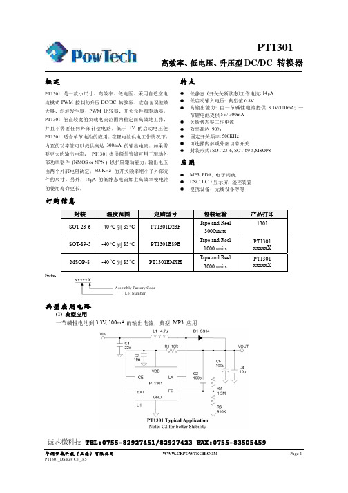
High EfficiencyLow Voltage Step-up DC/DC ConverterPT1301GENERATION DESCRIPTIONThe PT1301 is a compact, high efficiency, and low voltage step-up DC/DC converter with an Adaptive Current Mode PWM control loop. It comprises of an error amplifier, a ramp generator, a PWM comparator, a switch pass element and the driver. It provides stable and high efficient operation over a wide range of load currents without external compensation. The below 1V start-up input voltage makes PT1301 suitable for single battery cell applications. The built-in power transistor is able to provide up to 300mA output current while working under Li-Battery Supply. Besides, it provides extra pin to drive external power devices (NMOS or NPN ) in case higher output current is needed. The output voltage is set with two external resistors. The 500KHz high switching rate reduces the size of external components. Besides, the 14μA low quiescent current together with high efficiency maintains long battery lifetime.FEATURESz Low Quiescent (Switch-off) Supply Current: 14μA z Low Start-up Input V oltage: typical 0.8Vz High Supply Capability: Deliver 3.3V 100mA with1Alkaline Cell; 5V 300mA with 1 Li-Cell z Zero Shutdown Mode Supply Current z High efficiency: 90%z Fixed switching frequency: 500KHzz Options for internal or external power switches z Package type: SOT-23-6, SOT-89-5,MSOP8APPLICATIONSz MP3, PDA, Electronicz Dictionary, DSC, LCD, RF-Tag,z Portable Devices, Wireless Devices, etc.OREERING INFORMATIONPACKAGETEMPERATURERANGEORDERING PARTNUMBERTRANSPORT MEDIA MARKINGSOT-23-6 -40 o C 到85 o C PT1301D23F Tape and Reel 3000units 1301 SOT-89-5 -40 o C 到85 o C PT1301E89E Tape and Reel 1000 units PT1301 xxxxxX MSOP-8 -40 o C 到85 o C PT1301EMSHTape and Reel 3000unitsPT1301 xxxxxXNote:Assembly Factory CodeLot NumberLow Voltage Step-up DC/DC Converter TYPICAL APPLICATION CIRCUITS(1) Typical Application1 Alkaline Cell to 3.3V, 100mA Output Current, typically for MP3 Application.(2) Extending Output Current1 Alkaline Cell to 3.3V, 250mA Output CurrentLow Voltage Step-up DC/DC Converter(3) High Output Voltage, Large Output Current5V to 12V, 300mA Output CurrentPIN ASSIGNMENTPIN DESCRIPTIONPIN NoSOT-23-6 SOT-89-5 MSOP-8SYMBOL DESCRIPTTION1 1 3 CE Enable pin. PT1301 Shut-down when CE is low2 EXT Output pin for driving external power transistor3 5 4GNDGround4 45 LX Output for internal power switch5 2 6VDDPowerSupply6 3 2 FBFeedbackinput1,7,8 NC No connectionVDDM-SOP8NCNCLow Voltage Step-up DC/DC ConverterABSOLUTE MAXIMUM RATINGS (Note 1)SYMBOLITEMRATING UNIT V DD Supply V oltage -0.3~7.0V V V LX LX pin Switch V oltage -0.3~7.0V V V IO V oltage on other I/O pins -0.3V to (VDD+0.3V)I OUT LX pin Output Current 2.5 A I EXT EXT pin Drive Current 200mAPTR1 Package Thermal Resistance SOT-23-6, ΘJC 145 W/℃PTR2Package Thermal Resistance SOT-89-5, ΘJC 45 W/℃T OPT Operating Temperature Range -40~125 ℃ T STG Storage Temperature Range -65~150 ℃ T SOLDER Lead Temperature (Soldering)260℃, 10sNote1: Absolute Maximum Ratings are threshold limit values that must not be exceeded even for an instant underany condition. Moreover, such values for any two items must not be reached simultaneously. Operation above these absolute maximum ratings may cause degradation or permanent damage to the device. These are stress ratings only and do not necessarily imply functional operation below these limits.ELECTRICAL CHARACTERISTICS (Note 2,3,4)(V IN =1.5V , VDD=3.3V , load current=0, TA =25℃, unless otherwise specified. )SYMBOL ITEM TEST CONDITION MIN TYP MAX UNITV ST Startup V oltage IL =1mA -- 0.80 1.05 V V DD Operating VDD Range VDD pin Voltage 2 -- 6 V I OFF Shutdown Current I (V IN )CE Pin = 0V, VIN = 4.5V-- 0.01 1μAI SWITCH OFFSwitch-Off Current I(V DD ) VIN = 6V-- 14 25 μA I SWITCH Continuous Switching CurrentVIN = CE= 3.3V, VFB = GND0.22 0.24 0.7 mA I NO LOAD No Load Current I(V IN )VIN = 1.5V, VOUT = 3.3V-- 56 -- μA V REF Feedback Reference V oltage Close loop, VDD = 3.3V 1.225 1.25 1.275V Fs Switching Frequency VDD = 3.3V 400 500 600 KHz D MAX Maximum DutyVDD = 3.3V 85 94 -- % R ONLX On Resistance, LX to GND VDD = 3.3V -- 0.3 1.1 Ω I LIMIT Current LimitVDD = 3.3V1 1.52 A R ONEXTP On Resistance, EXT to VDD VDD = 3.3V -- 4.4 8.5 Ω R ONEXTN On Resistance, EXT to GND VDD = 3.3V -- 2.45 8.5 Ω △V LINE Line Regulation VIN = 3.5 ~ 6V, IL = 1mA -- 1.25 5 mV/V △V LOADLoad RegulationVIN = 2.5V, IL = 1 ~ 100mA--0.14--mV/mALow Voltage Step-up DC/DC ConverterELECTRICAL CHARACTERISTICS(Continued) (Note 2,3,4)SYMBOL ITEM TEST CONDITION MIN TYP MAXUNITVCE CE trigger Level VDD = 3.3V 0.4 0.8 1.2 VTS V outTemperatureCoefficient 50 ppm/℃TSD△ ThermalShutdownHysteresis-- 10 -- ℃Note 2:Electrical Characteristics state DC and AC electrical specifications under particular test conditions which guarantee specific performance limits. This assumes that the device is within the recommended operating Range. Specifications are not guaranteed for parameters where no limit is given, however, the typical value is a good indication of device performance.Note 3:Typicals are measured at 25˚C and represent the parametric norm.Note 4:Datasheet min/max specification limits are guaranteed by design, test, or statistical analysis. SIMPLIFIED BLOCK DIAGRAMTYPICAL OPERATING CHARACTERISTICS(1) Efficiency(1.1) V out=3.3V(1.2) V out=5.0VLow Voltage Step-up DC/DC Converter(2) Line Regulation (2.1) V out=3.3V(2.2) V out=5.0V(3) Load Regulation (3.1) Vout=3.3V(3.2) Vout=5.0VAPPLICATION INFORMATION1) Output Voltage SettingReferring to Typical Application Circuit 1, the output voltage of switching regulator (V out) is set with following equation:V out=(1+R1/R2)*Vfb2) Feedback Loop DesignReferring to Typical Application Circuit 1 again, the selection of R1 and R2 is a trade-off between quiescent current consumption and interference immunity besides abiding by the above equation. z Higher R reduces quiescent current( I=1.25V/R2 )z Lower R gives better interference immunity,and is less sensitive to interference, layout parasitic, FB node leakage, and improper probing to FB pin.Hence for applications without standby or suspend modes lower R1 and R2 values are preferred, while for applications concerning the currentconsumption in standby or suspend modes, higher values of R1 and R2 are needed. Such high impedance feedback loop is sensitive to any interference, which requires careful PCB layout and avoid any interference, especially to FB pin. To improve the system stability, a proper value capacitor between FB pin and V out is suggested. An empirical suggestion is around 100pF for M Ω feedback resistors and 10nF ~0.1uF for lower R values.3)PCB Layout GuidePCB Layout shall follow these guidelines for better system stability:z A full GND plane without any gap break.zVDD to GND bypass Cap – The 1μF MLCC noise bypass Cap between pin 5 and pin 3 shall have short and wide connections.zVin to GND bypass Cap – Add a Cap close to the inductor when Vin is not an idea voltage source.Low Voltage Step-up DC/DC Converterz Minimize the FB node copper area and keep it far away from noise sources. z Minimize the parasitic capacitance connected to LX and EXT nodes to reduce the switch loss.TEST CIRCUITSLow Voltage Step-up DC/DC ConverterPACKAGE INFORMATION(1) SOT-23-6DIMENSION ( in mm) DIMENSION ( in Inch)SYMBOLMIN MAX MIN MAXA 0.787 1.450 0.031 0.057A1 0.152 0.006B 1.397 1.803 0.055 0.071b 0.250 0.559 0.010 0.022C 2.591 2.997 0.102 0.118D 2.692 3.099 0.106 0.122e 0.838 1.041 0.033 0.041H 0.080 0.254 0.003 0.010L 0.300 0.610 0.012 0.024Low Voltage Step-up DC/DC ConverterPACKAGE INFORMATION(2) SOT-89-5DIMENSION ( in mm ) DIMENSION( in Inch )SYMBOLMIN MAX MIN MAXA 1.400 1.600 0.055 0.063b 0.460 0.520 0.014 0.020B 2.400 2.600 0.094 0.102b1 0.406 0.533 0.016 0.021C 4.250 0.1670.800 0.031C1D 4.400 4.600 0.173 0.181D1 1.700 0.067e 1.400 1.600 0.055 0.063H 0.380 0.430 0.014 0.017Low Voltage Step-up DC/DC ConverterPACKAGE INFORMATION(3) MSOP-8Millimeters Inches SymbolMinMaxMinMaxA 0.820 1.100 0.032 0.043 A1 0.0200.150 0.001 0.006 A2 0.7500.950 0.030 0.037 b 0.2500.380 0.010 0.015 c 0.0900.230 0.004 0.009 D 2.900 3.100 0.114 0.122 e 0.650(BSC) 0.026(BSC)E 2.900 3.100 0.114 0.122 E1 4.750 5.050 0.187 0.199 L 0.4000.800 0.016 0.031 θ 0° 6° 0° 6°。