水处理系统hmi操作手册
- 格式:docx
- 大小:522.58 KB
- 文档页数:20
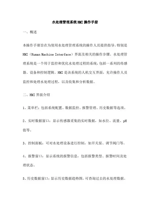
水处理管理系统HMI操作手册一、概述本操作手册旨在为使用水处理管理系统的操作人员提供指导,特别是HMI(Human Machine Interface)界面及相关的操作步骤。
水处理管理系统是一个用于监控和优化水处理过程的系统,包括一系列的传感器、设备和控制逻辑。
HMI是该系统的人机交互界面,允许操作人员监控和处理水处理过程,以及收集和分析数据。
二、HMI界面介绍1、菜单栏:包括系统配置、数据监控、报警管理、历史数据等选项。
2、实时数据窗口:显示传感器采集的实时数据,如水位、流量、pH 值等。
3、控制面板:可对水处理设备进行控制,如开关泵、调节阀门等。
4、报警窗口:显示系统的报警信息,包括报警类型、报警时间及处理状态。
5、历史数据窗口:显示历史数据趋势图,可查询过去的水处理数据。
三、操作步骤1、开机启动:打开HMI界面,系统自动初始化并加载上次退出时的配置。
2、数据监控:在实时数据窗口中,可以查看各个传感器的实时数据。
如需查看特定数据,可在数据窗口下方选择相应的传感器标签。
3、设备控制:在控制面板中,可根据需要开关泵、调节阀门等。
操作前请确认对设备及流程无影响。
4、报警处理:当有报警信息时,会在报警窗口中显示。
操作人员应根据报警信息进行处理,如确认报警、消除报警等。
5、数据存储和查询:在历史数据窗口中,可以查看过去的水处理数据。
选择时间段,系统将显示对应时间段的数据趋势图。
同时,系统会将所有数据存储在本地数据库中,以供查询和分析。
6、系统配置:在菜单栏中选择系统配置,可以对水处理管理系统进行配置,包括传感器配置、设备配置、报警配置等。
请根据实际需要进行配置。
7、关机退出:在菜单栏中选择关机退出,可关闭水处理管理系统。
退出前请确保所有操作已完成并无遗漏。
四、注意事项1、请严格按照操作步骤进行操作,避免误操作导致设备损坏或流程异常。
2、在进行设备控制时,请确认对设备及流程无影响。
如有疑问,请先咨询专业人员。

中水处理系统操作说明目录一、系统总则 (1)二、工艺流程说明 (1)三、中水处理系统主要设备操作及运行维护 (1)3.1 格栅 (1)3.1.1 功能原理 (1)3.1.2 工艺单元操作规程 (1)3.2 调节池 (2)3.2.1 功能原理 (2)3.2.2 主要设备及仪器仪表 (2)3.2.3 工艺单元操作规程 (2)3.2.4 注意事项 (2)3.3 缺氧池 (2)3.3.1 功能原理 (2)3.3.2 工艺单元操作规程 (3)3.4 生物接触氧化池 (3)3.4.1 功能原理 (3)3.4.2 主要设备及仪器仪表 (3)3.4.3 工艺单元操作规程 (3)3.5 沉淀池 (4)3.5.1 功能原理 (4)3.5.2 主要设备及仪器仪表 (4)3.5.3 工艺单元操作规程 (4)3.6中间水池 (4)3.6.1 功能原理 (4)3.6.2 主要设备及仪器仪表 (5)3.6.3 工艺单元操作规程 (5)3.7 石英砂过滤器 (5)3.7.1 功能原理 (5)3.7.2 主要设备与仪器仪表 (5)3.7.3 工艺单元操作规程 (5)3.8 化学药品投加 (6)3.8.1 主要设备及仪器仪表 (6)3.8.2 工艺单元操作规程 (6)3.8.3 消毒加药装置 (6)3.8.4 絮凝加药装置 (7)3.9 中水回用池 (7)3.9.1 功能原理 (7)3.9.2 主要设备及仪器仪表 (7)3.10 排污泵 (7)四、中水处理系统操作程序 (7)4.1 中水处理系统启动前的检查 (8)4.2 中水处理系统启动操作 (8)4.2.1 中水处理系统手动状态启动操作 (8)4.2.2 中水处理系统自动状态启动操作 (9)4.3 石英砂过滤器反洗 (10)五、中水处理系统设备运行与维护 (10)5.1 管道离心泵的运行与维护 (10)5.2 潜污泵的运行与维护 (11)5.3 回转式风机的运行与维护 (11)5.4 机械隔膜计量泵的运行与维护 (12)一、系统总则与中水处理站有关的管理人员、技术人员、操作人员必须熟悉、掌握水处理工程的工艺流程,了解各处理单元的作用及掌握其基本控制参数,熟悉各设备的操作,出现故障能及时解决或向管理人员反映,工作认真负责。

软件使用说明书目录1 系统说明1、中控系统介绍2、PLC柜介绍3、中控与PLC柜连接方法2 软件使用操作说明1、总界面介绍2、电机控制3、各工艺监控界面介绍4、模拟量说明5、曲线操作使用说明6、报表操作使用说明7、报警提示说明8、安全退出3 软件使用注意事项1 系统说明1、中控系统介绍1,软件介绍该监控软件是在组态软件的平台上开发出来的,本系统采用的组态软件是力控ForceControlV6.1监控组态软件。
它是北京三维力控科技根据当前的自动化技术的发展趋势,总结多年的开发、实践经验和大量的用户需求而设计开发的高端产品,V6.1在秉承V5.0成熟技术的基础上,对历史数据库、人机界面、I/O驱动调度等主要核心部分进行了大幅提升与改进,重新设计了其中的核心构件,力控6.1开发过程采用了先进软件工程方法:“测试驱动开发”,使产品的品质得到了充分的保证。
与力控早期产品相比,力控6.1产品在数据处理性能、容错能力、界面容器、报表等方面产生了巨大飞跃。
力控监控组态软件是对现场生产数据进行采集与过程控制的专用软件,最大的特点是能以灵活多样的“组态方式”而不是编程方式来进行系统集成,它提供了良好的用户开发界面和简捷的工程实现方法,只要将其预设置的各种软件模块进行简单的“组态”,便可以非常容易地实现和完成监控层的各项功能2,软件基本结构力控监控组态软件基本的程序及组件包括:工程管理器、人机界面VIEW、实时数据库DB、I/O驱动程序、控制策略生成器以及各种数据服务及扩展组件,其中实时数据库是系统的核心,组态软件结构图为:界面运行系统(View)用来运行由开发系统创建的画面,脚本、动画连接等工程,操作人员通过它来实现实时监控。
实时数据库(DB)是力控软件系统的数据处理核心,构建分布式应用系统的基础,它负责实时数据处理、历史数据存储、统计数据处理、报警处理、数据服务请求处理等。
I/O驱动程序(I/O Server)负责力控与控制设备的通信,它将I/O设备寄存器中的数据读出后,传送到力控的实时数据库,最后界面运行系统会在画面上动态显示。
水处理管理系统操作手册目录1、系统介绍2、工艺流程介绍3、界面操作介绍4、操作注意事项1、系统介绍改革开放后,国民经济的快速发展,人民生活水平的显著提高,同时也不断提高水体富营养化氨氮、磷等营养盐的问题拉动了污水处理的需求,国家环保局对污水排放标准也一步步提高,因此污水处理也是当前环保的当务之急。
不少污水处理工艺已经在工业中广泛应用,其对工厂排放污水的处理也具有重要的现实意义。
污水处理厂排出的污(废)水,因含污染物总量或浓度较高,达不到排放标准要求或不符合环境容量要求,从而降低水环境质量和功能目标时,必需经过人工强化处理的场所。
一般分为城市集中污水处理厂和各污染源分散污水处理厂,处理后排入水体或城市管道。
有时为了回收循环利用废水资源,需要提高处理后出水水质时则需建设污水回用或循环利用污水处理厂。
处理厂的处理工艺流程是有各种常用的或特殊的水处理方法优化组合而成的,包括各种物理法、化学法和生物法,要求技术先进,经济合理,费用最省。
设计时必须贯彻当前国家的各项建设方针和政策。
因此,从处理深度上,污水处理厂可能是一级、二级、三级或深度处理。
污水处理厂设计包括各种不同处理的构筑物,附属建筑物,管道的平面和高程设计并进行道路、绿化、管道综合、厂区给排水、污泥处置及处理系统管理自动化等设计,以保证污水处理厂达到处理效果稳定,满足设计要求,运行管理方便,技术先进,投资运行费用省等各种要求。
处理工艺:1、物理法:物理或机械的分离过程。
过滤,沉淀,离心分离,上浮等2、化学法:加入化学物质与污水中有害物质发生化学反应的转化过程。
中和,氧化,还原,分解,混凝,化学沉淀等3、物理化学法:物理化学的分离过程。
气提,吹脱,吸附,萃取,离子交换,电解电渗析,反渗透等4、生物法:微生物在污水中对有机物进行氧化,分解的新陈代谢过程。
活性污泥,生物滤池,生物转盘,氧化塘,厌气消化等。
反渗透法:反渗透法可以有效的清除溶解於水中的无机物,有机物,细菌,热原及其它颗粒等,是透析用水之处理中最重要的一环。

鄂钢中心水泵房水处理HMI控制要求及操作说明编制:姚旺2009年1月水处理设有独立的PLC控制系统。
主要通过PLC控制装置实现对整个水处理系统主要设备的监控,同时对其主要的仪表检测项目进行数据处理和显示。
二.HMI1.工艺流程画面中心水泵房水处理HMI画面分为五部分,(1)净环冷却系统,见附图1;(2)轧机浊环水系统,见附图2;(3)Mulpic浊环系统,见附图3;(4)其他水系统(加热炉软水池,旋流池,轧机泥浆调节池),见附图4;(5)过滤/砂滤器,见附图5。
过滤/砂滤器系统点击进去,显示AGF11,AGF12和5m高速过滤器的工作状态。
整个水处理各个控制部分的工艺流程分别在前四个HMI画面展现出来。
各控制设备的状态都在画面上用颜色变化或文字显示,点击相应的设备可弹出相应设备的状态,有设备启停控制、模式选择等按钮可供操作工操作控制。
点击控制设备的文字按钮,则弹出相应设备的控制操作画面。
画面上各设备基本状态有四种:灰色:代表该设备没供电,若画面按钮为灰色不可点击时,也表示该设备不具备控制条件。
红色:电机红色表示得电且准备好但没有运转,阀门红色表示关绿色:电机绿色表示该电机正在运转,阀门绿色表示开到位。
黄色:设备出现故障,会黄色闪烁,复位后黄色闪烁消除,若故障还存在会继续黄色闪烁,故障接触,则恢复到相应状态颜色。
所有的设备都有三种操作模式,机旁、检修、远程。
该模式的选择只能在设备的机旁操作箱选择。
选择机旁,此设备只能在现场机旁箱操作,PLC无法对其操作控制。
选择检修,设备机旁和PLC都不能对其控制。
选择远程,此设备可以通过PLC控制,由操作员操作WINCC 监控画面远程控制设备。
远程控制模式下又分手动和自动两种操作方式。
选择“手动”,就类似机旁操作,通过画面各个操作按钮启停相应的设备。
泵在手动模式下有启动和停止两种选择;阀门有开阀、关阀和停阀选择,阀门达到限位会自动停止动作,若开或关超过30秒自动停止并报错。
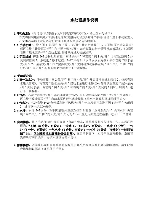
水处理操作说明1.手动过滤:(阀门运行状态指示及时间设定均在文本显示器上显示与操作)首先将控制电源旋钮右旋接通电源(红色指示灯点亮)并将“手动/自动”置于手动位置及在文本显示器上设定各运行时间(具体参照自动运行时间)。
1.1手动初滤:右旋“阀1关/开”和“阀6关/开”开启初滤阀门1、6(须有原水进入管道)后再右旋“计量泵关/开”和“搅拌机关/开”启动絮凝加药计量泵投加絮凝剂,然后再右旋“原水泵关/开”启动水泵,此时系统进入初滤过程。
1.2手动过滤:初滤3-5分钟以后右旋“阀5关/开”和左旋“阀6关/开”开启过滤阀5并关闭初滤阀6,系统进入净水过程,6-12小时后(以净水水质为准)依次左旋“原水泵关/开”、“计量泵关/开”和“搅拌机关/开”关闭动力设备再左旋“阀1关/开”和“阀5关/开”关闭阀1和阀5结束过滤进行下一步操作。
2.手动反冲洗2.1第一次水冲:手动右旋“阀2关/开”和“阀4关/开”开启反冲洗进水阀门2、4(须有清水进入管道), 再右旋“原水泵关/开”启动水泵进行水冲,2-4分钟以后左旋“反冲泵关/开”关闭水泵,再左旋“阀2关/开”和右旋“阀3关/开”关闭阀2同时开启阀3,进行下一步操作。
2.2气冲:右旋“风机关/开”启动风机进行气冲,2-3分钟后右旋“阀2关/开”开启阀2,再右旋“反冲泵关/开”启动水泵进行气水冲操作(排水电磁阀与风机同时开关)。
2.3气水冲:气冲完毕5-10分钟后左旋“风机关/开”停止风机并左旋“阀3关/开”关闭阀3,进行下一步水冲操作。
2.4水冲:水冲3-5分钟(时间以排出水浊度为准)后左旋“反冲泵关/开”关闭水泵,再左旋“阀2关/开”和“阀4关/开”关闭阀2、4,至此反冲洗过程结束,进入下一个循环。
3.自动操作:将“手动/自动”旋钮旋到“自动”状态,系统按控制流程进行工作。
其循环过程为:“初滤(3分钟,可设定)—过滤(6—12小时,可设定)—水冲(3分钟)—气冲(5分钟,可设定)—气水冲(8分钟,可设定)—水冲(4分钟,可设定)—转回初滤”(注:以上时间视水质设定仅供参考)。
OPERATIONMANUALEDDY WATER TREATMENT SYSTEM/watch?v=mwLcfelIuzcSYSTEM COMPONENTS2. T a n k m i x e r7. S e t t l i n g t a n k9. C o n t r o l p u m p4. F l o w C o n t r o l V a l v e3. T r a n s f e r p u m p (f r o m s u s p e n s i o n t a n k t o s e t t l i n g t a n k )5. I n j e c t i o n p o i n t f o r E d d y S e t a n d E d d y F l o c p r o d u c t s .6. M e t e r i n g p u m p f o r E d d y S e t a n d E d d y F l o c p r o d u c t s8. C a v i t y p u m p1. B u f f e r T a n k10. E n t r y b a s k e t f o r r e s i d ueREFERENCE NO. NAMEDESCRIPTIONA demonstration video of the system is available on our YouTube channel. You can view it by clicking on the following link.CONTROL PANEL WTS OPERATION PROCEDUREThe control panel allows you the activate the following components:PRE-START UP PROCEDURE1. Connect system to a 120/240 volt electric outlet.Test each electric component in the system in manual mode. • Main mixer • Transfer pump • Metering pump • Cavity pump • Secondary mixer2. Manually test the floater in the buffer tank in automatic mode to make sure it functions properly.3. Make sure the transfer pump hoses are well-connected and in the proper position before using the system.4. Connect the metering pump hose to the “T” found on transfer pump’s exit hose and place its vacuum part on the appropriate product (Eddy Set or Eddy Floc).5. If you are using additives during drilling, make sure to use the liquid Eddy Set product. (See documentation on “Drilling with Additives – Eddy Set” for detailed information.)6. If you are not using additives during drilling, make sure to use the Eddy Floc product and to make a smooth mix by using: 250 grams of powdered Eddy Floc added to 115 litres of clean water. Mix for one and a half hours.Attention: Do not empty the entire 250 gram packet of Eddy Floc all at once into the water as it will clump and become very difficult to mix. (See documentation on “Drilling without Additives – Eddy Floc” for detailed information.)7. Install the cavity pump’s exit hose.TRANSFER PUMP:• Transfers drill water from the buffer tank to the settling tank.• Three modes are available: automatic, manual and stop.METERING PUMP• Injects the decantation products into the line that transfers the additives. • Three modes are available: automatic, manual and stop.Attention: This pump works clockwise or counterclockwise. There will be a vacuum and an injection hose to install on the line that transfers additives. Once installation is complete, the same rotation direction must be maintained throughout the use of the pump.SUMP PUMP• Has an on and off function.• Is only used if you need to install a pump directly onto the casing to send the drill water back into the system. CAVITY PUMP• Eliminates treated drill solids from the decantation tank. • Moves water slowly at a speed of 19-23 litres/minute.• Three modes are available: automatic, manual and stop.• Works with the vibrator when in automatic mode.MAIN MIXER• Is found in the buffer tank.• Creates continuous movement in order to keep drilling drill water from settling.• Has an on and off function.SECONDARY MIXER (Eddy Floc) • Prepare products for decantation• Should be installed on the 115 litre container supplied with the system.• Use this container to dissolve the decantation products by mixing with the amount of water recommended.• Has an on and off function.SYSTEM IN OPERATIONOnce the system is in operation, follow these steps for proper ongoing operation of the system:1. Continue performing decantation tests for every 21 metres drilled throughout the entire period of operation.2. For every 3-6 metres drilled, check the level of solids by looking through the window found on the front of the settling tank.3. Once the level of the solids has reached the ¾ mark of the window, start the vibrator found on the side of the settling tank.4. Once the level of solids is above the window, start eliminating the solids by using the cavity pump function in manual mode, found on the control panel.5. Stop the elimination process once the level of solids is at the bottom 1/3 of the window.6. Stop the vibrator.7. Restart as needed.8. You must always verify the amount of product used (Eddy Set or Eddy Floc) to avoid improper operation of the system.PROCEDURE FOR SYSTEM START UP1. Check the two tanks to make sure there is no debris at the bottom, or in the cavity pump or settling tank.2. Fill the settling tank with clean water before starting the system.3. Install the drill water entry hose (which comes out of the casing directly) to fill the buffer tank (in the filter basket).4. Check to see what kind of drilling will be done to ensure use of the right product (Eddy Set for drilling with additives or Eddy Floc for drilling without additives).5. Put the system on manual.6. Fill the metering pump hose with the product to be used (Eddy Set or Eddy Floc) up to the “T” in the transfer line.7. Fill the buffer tank with drill water.8. Wait until the mixer’s blades are submerged before starting it.9. Follow the instructions of the product used to perform a decantation test in manual mode (See documentation on “Drilling with Additives – Eddy Set” or “Drilling without Additives – Eddy Floc” for more information).10. Once adjustment has been made to the level of the metering pump, switch the mode to automatic. 11. Pay attention while filling up the buffer tank to make sure that the level float works, well and is in the right position.12. When indicated by the level float, make sure the transfer pump and the metering pump are working simultaneously and that the metering pump is rotating in the right direction.(See “Control Panel – Metering Pump- for more information.)13. After slightly more than 30 seconds of pumping, perform another decantation test to confirm dosage and make sure the solids have settled.14. If you are using Eddy Floc and are drilling only with water, the system is now operational. Continue performing decantation tests every after 21 metres of drilling.15. If you are using Eddy Set and drilling with additives, you must make sure that the fluid viscosity remains the same throughout operations. If this is not the case, you must adjust your dosage accordingly with decantation tests. (See documentation on “Drilling with Additives – Eddy Set” for more information.)dust from rocks is not sufficient to counteract the floatation effect caused by the additives in the water. In this case, a reduction in viscosity could be considered and a change in the ratio of “Torqueless to DD-2000” would be recommended. If these measures are not enough to allow proper settling of the drill cuttings, it would be important to consider using the same bypass valve that controls viscosity, to recover drilling fluids that have a low level of rock dust. 4. pH level of waterThe importance of the pH level of the water used to prepare the drilling fluids also applies to the products used by the Fordia system. While preparing fluids, it is important to keep the pH level between 8 and 10. (Use of the product pH 10 is recommended.) It is important to note that geological formations may have a large effect on the pH level of water returning to the surface. It is important to monitor the pH level of the water entering Fordia’s system and to treat it if necessary. 5. Water salinityFordia would like to point out that like drilling fluid additives, the products used by Fordia’s system to treat water will be similarly affected by the presence of salty water in the circuit.6. Petroleum substancesFordia has no information on how the presence of liquid or gas petroleum will impact the drilling fluids in Fordia’s system. In these cases, adjustments may be necessary to optimize the operation of Fordia’s water treatment system. 7. Drilling mud handlingFordia would like to point out that the use of drilling additives will greatly increase the amount of drilling mud exiting the system. Handling about 7,500 litres of drilling mud per day is to be expected.Fordia has no responsibility regarding the drilling mud that exits the system. This remains the responsibility of the user.8. Freezing Eddy SetFordia would like to point out that the Eddy Set product in liquid form should not be frozen. Once frozen it will lose its strength. Makes sure to protect it from freezing.WTS LIMITATIONS1. Variability of drilling fluid viscosityWhen drilling with additives or polymers and using the Eddy Set product, maintaining the same drilling fluid viscosity is crucial, as this will ensure minimal manipulation of the system. We recommend using a Marsh funnel to measure viscosity at the drill rig entrance. This measurement (i.e. 38 seconds) should remain the same in order to avoid having to adjust the amount of Eddy Set through the use of the metering pump. It is also important to monitor the viscosity at the exit of the casing as this will directly affect the efficiency of the system. This measurement should be 5 to 10 seconds less than the measure of viscosity at the entrance of the drill rig (i.e. 32 seconds).It should be noted that certain procedures may influence the viscosity of fluids at the exit of the casing, specifically, the “pumping action” or “water circulation”, and during core recovery. The fluids recuperated during these two processes are not “used” drill water and will not have undergone the shearing effect of the polymer strings by the diamond tool at the bottom of the hole. As a result this fluid will have a viscosity similar to that at the entrance of the drill rig.Fordia strongly recommends using a bypass valve to recover fluids that have not been “used” from the buffer tank so they can be re-used. This will allow you to better control the viscosity of fluids entering Fordia’s system, and will also provide a substantial cost savings of the drilling additives required to prepare drilling fluids.2. Use of bentonite/baryteTests have shown that Fordia’s system CANNOT , on a regular basis, treat drilling fluids with a density greater than 1.2.If Bentonite and/or Baryte must be used to balance pressure or for any other reason, Fordia recommends that the drilling fluids entering the system are diluted so that the density of the fluids to be treated will be reduced. Once diluted, Fordia’s system will be able to treat the drilling fluids, but in this case, the amount of the Eddy Set product will need to be adjusted.3. Drilling ProcessWhen the rate of penetration is low or while reaming the bore hole, it is very possible that the amount ofEDDY MAINTENANCE• Clean the point where decantation products are injected and the non-return valve every 3 days.(See page 3 to view the system components)• Check the level of transmission oil in the main mixer every week.• Lubricate the cavity pump monthly.• During cold temperatures (lower than 0o Celsius), make sure to empty all debris from the pumps in the tanks to make sure it does not freeze and damage the equipment.ADDITIONAL INFORMATIONIf the rate of used drill water flowing from the buffer tank to the settling tank decreases, this is a sign that thetransfer pump could be blocked. In this case, the pump will have to be opened and full maintenance performed.If the pump shuts off frequently, this is a sign of an obstruction. Complete maintenance is required to removethe blockage.If the density of the drill water to be treated is not high enough, meaning that the used drill water is not heavyenough to undergo decantation through normal operation of the system, a technician must be contacted in orderto adjust the system operation parameters. This uncommon situation can arise for example, when drilling in rockthat is very light and while the casing is being installed. Low-density drill water can then float to the surface ofthe settling tank. Should this occur, a Fordia technician can advise you with instructions.NECESSARY PLUGS FOR WATER SYSTEM GENERATORGenerator typeL 14-30 (125/250V, 30A)Water system male plug typeHBL 2711 (125/250V, 30A)Phone: 514 336 9211T ollfree:180****7274Email:***************。
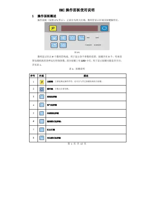
第 1 页 共 15 页HMI 操作面板使用说明1 操作面板概述操作面板(如图1-1所示),正面分为两大区域:数码管显示区域及按键操作区。
图1-1数码显示区由6个数码管构成,用于显示各个参数的设置。
按键共有8个,用来设置包缝机机的各种运行控制参数,部分按键上有LED 小灯,用于显示按键功能是否开启,详见表1。
表1:按键说明序号 外观描述1功能键:主要起确定操作作用,还可以与其它按键组成组合按键。
2 循环键:小数点位置切换。
3剪线选择键4吸气选择键5传感器选择键6缝制模式选择键:7机头灯键8布边模式选择键2用户模式定义2.1操作员模式此模式为操作面板的默认模式,操作面板上电后自动进入此模式。
进入此模式,6个数码管上的小数点位会两个相连的数码管小数点移动显示(屏幕显示),表示HMI处于空闲状态。
在执行任何操作的时候,如果长时间不按按键的话,HMI会自动切换到空闲状态,前一执行的操作将不会被执行!2.1.1全自动/半自动/全手工模式设置:全自动模式:按5键,再按下6键,两个无先后顺序。
5键灯亮,6键灯亮。
半自动模式:5键灯亮,6键灯灭。
全手工模式:5键灯灭,6键灯灭。
2.1.2剪线模式设置:。
当3按键上面两个LED灯都不点亮的时候,表示没有剪线;当3按键左上方LED灯点亮,右上方不亮的时候,表示前剪线;当3按键左上方LED灯不亮,右上方点亮的时候,表示后剪线;当3按键左上方、右上方LED灯都点亮的时候,表示前后均剪线。
2.1.3吸气模式设置:。
当4按键上面两个LED灯都不点亮的时候,表示没有吸气;当4按键左上方LED灯点亮,右上方不亮的时候,表示前吸气;当4按键左上方LED灯不亮,右上方点亮的时候,表示后吸气;第 2 页共 15 页当4按键左上方、右上方LED灯都点亮的时候,表示前后均吸气。
2.1.4机头灯设置:当按下7后,键角LED灯会亮,机头灯点亮。
再按一下键左上角LED灯会熄灭,机头灯灭。
2.1.5布边模式设置:当8按键上面两个LED灯都不点亮的时候,表示没有拖布;当8按键左上方LED灯点亮,右上方不亮的时候,表示前拖布;当8按键左上方LED灯不亮,右上方点亮的时候,表示后拖布;当8按键左上方、右上方LED灯都点亮的时候,表示前后均拖布。
昆明烟厂太阳能预热洗涤热水系统操作员站HMI操作简易说明书(2011-8)操作员站 (1)HMI操作简易说明书 (1)HMI系统概述 (3)软件系统架构 (3)窗口操作介绍 (3)登录窗口 (3)功能操作栏 (3)常规主画面 (4)用户注销 (4)确认退出对话框 (5)报警浏览窗口 (5)报警历史程序窗口 (6)模拟量趋势 (7)操作记录查询画面 (8)标准模块窗口 (8)工程参数设定画面 (8)电机操作画面 (10)HMI系统概述软件系统架构昆明烟厂太阳能预热洗涤热水系统采用1个Pannelview触摸屏做操作员站和工程师站,HMI系统采用FTView上位机软件,通过RS232链接Controllogix,采用RSLinx Enterprise OPC连接方式获取PLC中的数据。
窗口操作介绍登录窗口图2 登录窗口当操作员站触摸屏启动后,会自动加载HMI程序,程序启动后,会提示输入操作员用户名和密码,只有有权限登录的人员才能登录本系统。
功能操作栏图3 功能操作栏所有主画面的底部均为此操作栏,用于一些功能画面的导航。
点击左边4个按钮将弹出菜单窗口栏,用于直接导航切换到相应到画面。
点击历史趋势将切换到历史趋势窗口,点击状态图将切换到当前工艺主画面。
点击操作参数按钮,将显示可以操作的水泵、电磁阀启停、开闭。
点击工程参数按钮将切换到工程参数设定画面。
常规主画面图4 常规主画面本画面为系统中较常规的画面,集中了绝大部分画面元素。
大部分画面元素是根据PID 画面所制,每个监控点都有一个KKS编码与之对应,点击画面上的不同监控点,会弹出相应的操作小窗口用于操作。
如果本画面中有相应的顺控子组操作,则会放置相应的顺控操作按钮。
用户注销图5 确认注销对话框当点击任意一个主画面上的用户注销按钮时,将注销当前登录用户,为只能查看状态,不能做任何操作的权限画面。
当用户重新登录,才能根据分配的用户权限操作或设定工程参数。
权限分配是按照操作员组来划分的,系统中预留5个组,分别是管理员组,操作员组1,操作员组2,操作员组3,默认组,所有的用户分属于不同的组。
厦门海为科技有限公司HMI 高清高速物联云HMI 使用说明目录产品说明一、产品介绍 (3)1.主要功能 (3)2.技术特点 (3)二、产品规格 (3)三、HMI配套软件 (4)四、HMI接口示意图 (5)软件使用说明一、HMI连接设置 (6)1.注意事项及硬件安装步骤 (6)1.1注意事项 (6)1.2硬件安装步骤 (6)2.硬件接线 (6)2.1设备连接电源 (6)2.2设备连接 (6)3.连接网络 (6)二、工程运行 (7)1.选择设备 (7)2.下载工程 (7)3.运行工程 (8)三、HMI管理器 (8)1.进入设备管理界面 (8)1.1本地管理器 (8)1.2云管理器 (9)2.执行设备管理 (9)2.1下载工程 (9)2.2上载工程 (10)2.3离线更新 (10)2.4启用校准 (10)2.5更新设备时间 (10)2.6获取PN码 (10)2.7检测设备版本 (11)2.8历史记录上传 (11)2.9重启设备 (13)四、后台设置 (13)1.工程设置 (14)1.1连接网络工程 (14)1.2下载工程 (14)2.网络设置 (16)2.1以太网连接 (16)2.2WIFI设置 (16)2.3个人热点 (18)2.4网络配置型号 (20)2.5路由配置 (20)3.本机设置 (22)3.1本机设置 (22)3.2安全设置 (24)3.3其他设置 (26)4.系统信息 (27)5.云设置 (29)6.多语言设置 (30)7.退出后台设置 (30)产品说明一、产品介绍1.主要功能海为HMI嵌入式系统是一款运行于工业自动化监控管理设备的嵌入式系统软件,通过运行海为组态工程,可以实现直观的观察到工业的现场情况,与各种工业控制设备进行通信,通过采集到的工业现场的生产信号,对其进行监控。
对工业现场的报警信息通过画面、计算机语言、微信、短信、邮件等形式,及时通知相关工作人员。
支持网络工程的使用,使多个设备之间可互为客户端和服务器,通过网络共享数据,实现分布式控制。
污水处理系统工程电气控制操作手册(东区)一、开机画面,按“进入系统”按钮,进入系统操作。
二、主画面,主画面下面设置7个功能键,触动这7个功能键,可进入对系统进行不同的功能操作界面。
为了进入这7个功能键,需要不同的用户名和密码。
输入正确的用户名和密码后,可以触动进入相应的功能键;如果超过5分钟没有操作,此时用户名和密码失效,需要重新输入用户名和密码,才能进入功能键。
三、自动运行操作画面自动操作画面分为“生产废水处理系统自动”操作按钮和“生活污水处理系统自动”操作按钮。
同时,分别各自单独设置了污泥自动排泥按钮,自动排泥按钮,可以使排泥泵根据设定好的排泥时间和排泥间隔时间,自动排泥。
在自动运行操作画面按右上角的下一页按钮,进入活性污泥驯养调试操作界面。
活性污泥自动驯养功能界面,内部初始设置为:鼓风机连续曝气时间240分钟,这段时间曝气是为了活性污泥的驯化和生长;鼓风机停歇曝气时间120分钟,这段时间是为了补水之前使混合液中的活性污泥充分沉淀,以免在补水的过程中活性污泥流失;调节池潜水泵补水时间为15分钟,这段时间是为了向生化池中补充部分污水,为活性污泥提供存活所必须的营养物质,如果此时调节池生活污水处于低液位,没有污水补充,可以向生化池中投加葡萄糖和尿素,投加量参考操作手册药剂使用说明;补水后静置时间为30分钟,这段时间是为了补充水之后,使二级生化池具有足够时间将上清液充分溢流排出,保证生化池液位不高于溢流管,避免后续启动鼓风机后,混合液携带活性污泥大量流失。
如果在调试过程中认为初始设置时间需要调整,可在画面上输入你认为正确的时间即可。
四、手动操作界面触摸手动按钮,可以直接启停相应设备和水泵,其中水泵受到相应液位计的低低液位设定值保护和启动也受到相应液位计的低高液位设定值限制。
酸碱加药泵受到Ph设定值限制。
(通常情况下,要求现场操作人员在带有设备联动的现场控制箱执行手动操作,并随时观察设施运行情况。
该主控柜手动操作界面没有设备联动,主要用于专业人员使用和配药手动操作)生活污水处理系统正常运行时,生活污水污泥沉淀池排泥泵是将沉淀池底部活性污泥回流至缺氧池,使其重新进入生化系统参与污水处理,此时不得手动开启此泵超过6分钟。
C厂房纯水站控制画面操作说明本系统采用西门子公司的winCC组态开发软件,通过CP5611通讯卡的Profibus DP通讯协议连接到PLC,实现远程监视和操作。
C厂房纯水站控制画面由九个画面组成,分别是:主画面、原水控制、超滤、一级RO、二级RO、EDI、纯水外供、在线数据、报警画面。
下面按照工艺流程详细讲述操作过程。
一、怎样进入winCC组态画面:首先在电脑桌面中找到SIMATIC WinCC Explorer图标,双击即可打开,点击画面左上角的三角形图标(启动按钮),等待系统加载后就进入了C厂房纯水站控制画面的主画面中,这时是没有任何站点登录,所以不能切换画面,点击主菜单中的登录按钮,选择操作员站登录(用户名:czy1 密码:123456),或者选择工程师站点登录(用户名:gcs1 密码:123456)。
如果进入的是操作员站点,则只能操作主系统的启动和停止、分系统的启动和停止,此站点是不能进行参数修改的。
如果进入的是工程师站点,则可以进行参数修改等功能。
二、主画面主画面是用来监控整个系统运行功能的,显示各系统的电机、水箱液位、水泵出口压力、各级电导、电阻、ORP等运行参数。
主画面是不用来操作的,只起监视作用。
平时监控系统操作完成后一律返回主画面状态下。
每个画面的左上角都有一个隐藏的报警指示器,平时没有报警时处于隐藏状态,当有报警时,被隐藏的报警指示器会闪烁,并发出报警铃声,提醒操作人员注意。
点击报警画面或者直接点击闪烁的报警指示器都可进入报警画面,画面中会显示报警信息的内容,操作员第一时间对报警信息的内容进行分析处理,等报警的故障复位后方可点击报警画面中的取消报警按钮,从而取消报警。
(此处请大家注意,必须是先去现场复位故障后,才能点击取消报警按钮,因为有些故障报警时带有联锁功能的,如果不及时处理,会产生故障停机的危险)三、原水控制画面原水控制画面中显示的是原水系统的运行情况1、全系统一键控制菜单画面的右上角有一个全系统一键控制菜单,点击该菜单中的启动按钮,整个系统就会处于运行状态,此时该处的状态指示灯会变绿色;点击停止按钮,整个系统就会停机,此时该处的状态指示灯会变红色。
5012618102-H8022012-11-19HMC08 High Color Wide Screen‧‧User-Friendly HMI ProductsInstrunction Sheet(1)PrefaceThank you for purchasing DELTA’s HMC series. This instruction sheet will be helpful in the installation, wiring and inspection of Delta HMI. Before using the product, please read this instruction sheet to ensure correct use. You should thoroughly understand all safety precautions before proceeding with the installation, wiring and operation. Place this instruction sheet in a safe location for future reference. Please observe the following precautions:⏹Install the product in a clean and dry location free from corrosive and inflammable gases or liquids.⏹Ensure that all wiring instructions and recommendations are followed.⏹Ensure that HMI is correctly connected to a ground. The grounding method must comply with the electricalstandard of the country (Please refer to NFPA 70: National Electrical Code, 2005 Ed.).⏹Do not disassemble HMI, modify or remove wiring when power is applied to HMI.⏹Do not touch the power supply during operation. Otherwise, it may cause electric shock.If you have any questions during operation, please contact our local distributors or Delta sales representatives.The content of this instruction sheet may be revised without prior notice. Please consult our distributors or download the most updated version at /ia.(2)Safety PrecautionsCarefully note and observe the following safety precautions when receiving, inspecting, installing, operating, maintaining and troubleshooting. The following words, DANGER, WARNING and STOP are used to mark safety precautions when(3)Model ExplanationHMC 08 - N 5 00 S 5 2(1) (2) (3)(4)(5) (6)(7)(8)(1) Product Name HMC: HMI with Controller(2) LCM Size 08: 8 inch TFT LCD(3) Type of Industries N: General Purpose(4) Display specification 5: SVGA(5) Version(6) Type of Model S: Standard ( built-in)(7) External Control Interface (Bus) 5: DMCNET(8) Controller Remote Unit interface 2: Specialized High-speed RS-422(4)Parts NamesHMC08-N500S52(Front View)A Power LED Indicator()Lights in green when HMI works normally.BOperation LED Indicator()/Alarm LED Indicator()Lights in blue: the communication is carried out /the data isaccessing. (Please refer to the “Note” below for explanation).Lights in red: one of the alarms is on.C Touch Screen / DisplayNote: The definition of the operation LED indicator (Blue) can be determined by the users freely.HMC08-N500S52(Rear View)A Power Input Terminal G USB HostBCOM3 (It is provided with two LEDindicators to indicate that HMI is inRead or Write status during thecommunication process.)H Audio Output InterfaceCCOM2 (It is provided with two LEDindicators to indicate that HMI is inRead or Write status during thecommunication process.)IMemory Card Slot / BatteryCoverD COM1 J DMCNETE USB Slave K Remote Module InterfaceF Ethernet Interface(LAN)(5)Installation and Storage ConditionsThe product should be kept in the shipping carton before installation. In order to retain the warranty coverage, the HMIshould be stored properly when it is not to be used for an extended period of time. Some storage suggestions are:⏹Store in a clean and dry location free from direct sunlight.⏹Store within an ambient temperature range of -20°C to +60°C (-4°F to 140°F).⏹Store within a relative humidity range of 10% to 90% and non-condensing.⏹Do not store the HMI in a place subjected to corrosive gases and liquids.⏹Correctly packaged and placed on a solid and durable surface.⏹Do not mount the HMI adjacent to heat-radiating elements or in direct sunlight.⏹Do not mount the HMI in a location subjected to corrosive gases, liquids, or airborne dust or metallic particles.⏹Do not mount the HMI in a location where temperatures and humidity will exceed specification.⏹Do not mount the HMI in a location where vibration and shock will exceed specification.⏹Do not mount the HMI in a location where it will be subjected to high levels of electromagnetic radiation.(6)Installation and WiringInstallation Notes:⏹Improper installation will result in malfunction and greatly reduce the life of the HMI. Be sure to follow theguidelines in this quick start when installing the HMI.⏹In order to ensure the HMI being well ventilated, make sure that the ventilation holes are not obstructed andmust provide sufficient free space around HMI.⏹To ensure the panel is well protected, be sure to install a waterproof gasket into HMI.⏹For use on a flat surface of a Type 4X "Indoor Use Only" enclosure or equivalent.⏹The allowable thickness of the panel for mounting should be less than 5 mm.Installation Method:Step 1:Ensure to put waterproof gasket into HMI and theninsert the HMI into the panel cutout.Step 2:Ensure to insert fasteners into the HMI’sinsertion slots and turn the screw till screwstouch panel cutout.Step 3:Turn the screw with less than torque 0.7N.M toavoid damage to plastic box.Torque: 6.17lb-inch (0.7N-M)Step 4:Keep at least 60mm distance from rear of HMIproduct to the wall, installation surface or theother controllers for heat dissipation.Recommended wiring is in the table below:Type Wire Gauge (AWG) Stripped length TorqueSolid 28 ~ 12 7 ~ 8 mm 5 kg-cm(4.3 lb-in)Stranded 30 ~ 12 7 ~ 8 mm 5 kg-cm(4.3 lb-in)Be sure to perform wiring by referring to the following figure (power supply connector).BA ECALL NOW 800-985-6929/Email:***********************Email:***********************(7)Basic InspectionGeneral Inspection ●Periodically inspect the screws of the connection between the HMI and device.Tighten screws as necessary as they may loosen due to vibration and varying temperatures.●Ensure that oil, water, metallic particles or any foreign objects do not fall insidethe HMI, control panel or ventilation slots and holes. As these will cause damage.●Ensure the correct installation and the control panel. It should be free fromairborne dust, harmful gases or liquids.Inspection before operation (power is notapplied) ●Ensure that all wiring terminals are correctly insulated.●Ensure that all wiring is correct or damage and or malfunction may result.●Visually check to ensure that there are not any unused screws, metal strips, anyconductive or inflammable materials inside HMI.●Ensure to lower electromagnetic interference when devices are influenced by it.●Ensure that the external applied voltage to HMI is correct and matched to thecontroller.Inspection before operation (power isapplied) ●Check if power LED lights.●Check if the communication among devices is normal.●Please contact our local distributors or Delta sales representative if there are anyabnormal conditions.(8)Pin Definition of Serial Communication COM1 Port(Supports Flow Control)COM Port PIN Contact RS-23212 RXD3 TXD45 GND67 RTS8 CTS9 Note: Blank = No Connection.COM2 Port(Supports Flow Control)COM Port PIN MODE1 MODE2 MODE3 RS-232 RS-422 RS-4851 TXD+ D+2 RXD3 TXD4 RXD+5 GND GND GND6 TXD- D-7 RTS8 CTS9 RXD- Note1: Blank = No Connection.Note2: When COM2 port is used for RS-232 flow control, i.e. RTS and CTS signals are used for flow control, COM3 port will become incapable of being used.Note3: When COM2 port is used for RS-422 flow control, please refer to the following COM3 Port signals table for pin assignments. The signals, RTS+, CTS+, RTS- and CTS- shown in brackets are the signals used for flow control.COM3 PortCOM Port PIN MODE1 MODE2 MODE3 RS-232 RS-422 RS-4851TXD+(RTS+)D+2 RXD3 TXD4 RXD+(CTS+)5 GND GND GND6 TXD-(RTS-) D-789 RXD-(CTS-)Note1: Blank = No Connection.Note2: When COM2 port is used for RS-422 flow control, please refer to the COM3 Port signals table above for pin assignments. The signals, RTS+, CTS+, RTS- and CTS- shown in brackets are the signals used for flow control.Ethernet Interface (LAN)Ethernet Interface (LAN) PIN Contact Ethernet1 TX+2 TX-3 RX+456 RX-78Note: Blank = No Connection. DMCNETEthernet Interface(LAN) PIN MODE1 D1+2 D1-3 D2+456 D2-78Note: Blank = No Connection.Remote ModuleEthernet Interface (LAN) PIN Contact1234 TX+5 TX-67 RX+8 RX-Note: Blank = No Connection.(9) DimensionsHMC08-N500S52(10) SpecificationsMODEL HMC08-N500S52LCD MODULE Display Type 8” TFT LCD (65536 colors)Resolution 800 x 600 pixelsBacklight LED Back Light(less than 20,000 hours half-life at 25o C) (Note 1)Display Size 162 x 121.5mmOperation System Delta Real Time OSMCUHMI 32-bit RISC Micro-controllerController 32-bit DSPNOR Flash ROMFlash ROM 128 MB(OS System: 30MB / Backup: 16MB / User Application:82MB)SDRAM 64MbytesBackup Memory(Bytes)16MbytesSoundEffectOutputBuzzer Multi-Tone Frequency (2K ~ 4K Hz) /85dBAUX Stereo outputEthernet InterfaceIEEE 802.3, IEEE 802.3u10/100 Mbps auto-sensing((has built-in isolated power circuit (Note 3))Memory Card SD Card (supports SDHC)USB 1 USB Host (Note 2) Ver 1.1 / 1 USB Slave Ver 2.0SerialCOMPortCOM1 RS-232(supports hardware flow control)COM2RS-232/RS-422/RS-485(has built-in isolated power circuit (Note 3))COM3RS-232/RS-422/RS-485(has built-in isolated power circuit (Note 3))Remote I/O Specialized 10M bps RS-422Motion Control Bus DMCNETFunction Key N/APerpetual Calendar Built-inCooling Method Natural air circulationSafety Approval CE/UL (Note 4)/KCC (Note 4)Waterproof Degree IP65/NEMA4Operation Voltage(Note5)DC +24V(-10% ~ +15%)(has built-in isolated power circuit (Note 3))Voltage EnduranceAC500V for 1 minute (between charging (DC24V terminal)and FG terminals)Power Consumption(Note 5)11 WBackup Battery 3V lithium battery CR2032 x 1Backup Battery LifeIt depends on the temperature used and the conditions of usage,about 3 years or more at 25o C.OperationTemperature 0oC ~ 50o CStorage Temperature -20o C ~ +60o CAmbient Humidity 10% ~ 90% RH【0 ~ 40o C】,10% ~ 55% RH【41 ~ 50o C】,Pollution Degree 2Vibration IEC 61131-2 compliant 5Hz≦f<8.3Hz = Continuous: 3.5mm, 8.3Hz≦f≦150Hz =Continuous: 1.0gShockIEC 60068-2-27 compliant 15g peak for 11 ms duration, X, Y, Z directions for 6timesDimensions(W) x (H) x (D) mm227.1 x 174.1 x 61Panel Cutout(W) x (H) mm219.4 X 166.5Weight Approx.1314 gis supplied to HMI. The life of LED backlight shown here is an estimated value under 25o C normal temperature andhumidity conditions.2) USB Host port can provide up to 5V/ 500mA of power.3) The withstand voltage of the isolated power circuit is 1500V peak for 1 minute.4) Some models are in the process of application to UL and KCC certification. For more information, please consultour distributors.5) The value of the power consumption indicates the electrical power consumed by HMI only without connecting toany peripheral devices. In order to ensure the normal operation, it is recommended to use a power supply whichthe capacity is 1.5 ~2 times the value of the power consumption.6) Users can download the Screen Editor V2.00, the program editor of Delta HMI product and the user manual via thefollowing link: /ia.7) The content of this quick start may be revised without prior notice. Please consult our distributors or download themost updated version at /ia.PIN1PIN1PIN1CALL NOW 800-985-6929/Email:***********************5012618102-H8022012-11-19HMC08 Yüksek Renk ‧Geniş Ekran‧Kullanımı Kolay HMI ÜrünleriBilgi Dokümanı(1) ÖnsözDELTA’nın HMC serisi operatör panellerini seçtiğiniz için teşekkürler. Bu bilgi dokümanı Delta HMI kurulum, bağlantı, bakım ve kontrolünde kullanıcıya yardımcı olacaktır. Doğru kullanım için ürünü kullanmadan önce bu dokümanı mutlaka okuyunuz. Kurulum, bağlantı ve çalışma yapmadan önce güvenlik uyarılarını tamamen anladığınızdan emin olunuz. Bu dokümanı daha sonra da kullanmak için iyi muhafaza ediniz. Lütfen aşağıdaki güvenlik uyarılarına dikkat ediniz:⏹ Ürününkurulumunuyanıcı gaz ve sıvılardan uzak kuru ve temiz ortamlara yapınız.⏹ Bağlantıları yaparken tüm bağlantı kurallarının sağlandığından emin olunuz.⏹ HMI’nın toprak bağlantısının doğru yapıldığından emin olunuz. Topraklama metodunun ürünün kurulduğu ülkestandartlarına uygun olduğuna emin olunuz (NFPA 70: National Electrical Code, 2005 Ed.).⏹HMI enerjili iken kablo bağlantısı yapmayınız ya da sökmeyiniz.⏹ Çalışma sırasında enerji besleme terminallerine dokunmayınız. Aksi halde elektrik şoku olabilir.Ürünün kullanımı ile ilgili sorularınız için, lütfen teknik servisimizle bağlantıya geçiniz. Herhangi bir ihbara gerek kalmaksızın bu bilgi dokümanının içeriği değiştirilebilir. Güncellenmiş versiyonu elde etmek için teknik servise danışabilir veya internet adresinden indirebilirsiniz. /ia(2) Güvenlik UyarılarıÜrünü alırken, kontrol ederken, kurulumunu yaparken, çalıştırırken, bakım ve arıza teşhisi yaparken aşağıdaki güvenlik uyarılarına dikkat ediniz. DANGER, WARNING, ve STOP başlıkları DELTA HMI ürününü kullanırken yapılması(3) Model AçıklamasıHMC 08 - N 5 00 S 5 2(1) (2) (3)(4)(5) (6)(7)(8)(1) ÜrünAdıHMC: Dahili Kontrolörlü HMI(2) LCM boyutu 08: 8-inch TFT LCD(3) Endüstri Tipi N: Genel Amaçlı(4) Display özellikleri 5: SVGA(5) Versiyon(6) Model Tipi S: Standart (dahili)(7) Harici Kontrol Arabirimi (Bus) 5: DMCNET(8) Uzak Birim Kontrolör Arabirimi 2: Özelleştirilmiş Yüksek-hızlı RS-422(4) Parça AdlarıHMC08-N500S52(Ön Görünüm)A Power LED Göstergesi()HMI normal olarak çalışıyorken ışık Yeşil yanar.BÇalışma LED Göstergesi()/Alarm LED Göstergesi()Haberleşme gerçekleştiriliyor/Verilere erişiliyor iken Maviyanar. (Açıklama için “Not” bölümüne bakınız).Alarmlardan herhangi biri ON iken Kırmızı yanar.C Dokunmatik Ekran / DisplayNot:Çalışma LED göstergesi (mavi) tanımlaması serbest olarak kullanıcı tarafından tespit edilebilir.HMC08-N500S52(Arka Görünüm)A Power Giriş Terminali G USB HostBCOM3 (HMI’nın haberleşme sırasındaokuma ve yazma durumunu gösterir ikiadet LED gösterge vardır.)H Audio Çıkış ArabirimiCCOM2 (HMI’nın haberleşme sırasındaokuma ve yazma durumunu gösterir ikiadet LED gösterge vardır.)IHafıza kartı slotu / PilkapağıD COM1 J DMCNETE USB Slave K Uzak Modül ArabirimiF Ethernet Arabirimi(LAN)(5) Kurulum ve Saklama KoşullarıKurulum yapılana kadar ürün orjinal kutusu içinde muhafaza edilmelidir. Ürünün garanti kapsamının devamı için, ürünbelli bir süre kullanılmayacaksa, HMI uygun bir şekilde saklanmalıdır. Bazı saklama önerileri:⏹ Doğrudan güneşışığının temas etmediği kuru ve temiz ortamda saklanmalıdır.⏹-20°C - +60°C (-4°F - 140°F) sıcaklık aralığında saklanmalıdır.⏹10% - 90% rutubet aralığında ve yoğuşmasız ortamda saklanmalıdır.⏹ HMIaşındırıcı sıvı ve gaz bulunan ortamlarda saklanmamalıdır.⏹Ürün uygun paketlenmeli, sert ve düz bir yüzeyde saklanmalıdır.⏹ HMIdoğrudan güneşışığının temas ettiği yerlere ya da ısı yayan nesnelerin yakınına montajı yapılmamalıdır.⏹ HMIaşındırıcı gaz ve sıvının olduğu toz veya metal parçacıkların bulunduğu yerlere montajı yapılmamalıdır.⏹HMI dokümanda belirtilen sıcaklık ve rutubet oranları dışında ortamlara montajı yapılmamalıdır.⏹HMI dokümanda belirtilen titreşim ve şok oranlarının üzerindeki ortamlara montajı yapılmamalıdır.⏹HMI yüksek seviyede elektromanyetik radyasyonun bulunduğu ortamlara montajı yapılmamalıdır.(6) Kurulum ve BağlantıKurulum Notları:⏹ Yanlış kurulum yapılması ürünün zarar görmesini veya çalışma ömrünün kısalmasına sebep olur. HMIkurulumunun doküman da belirtildiği gibi yapılması gerekir⏹ HMI’nın havalandırmasının doğru olduğuna emin olmak için, havalandırma deliklerinin tıkalı olmadığına ve HMIetrafında gerekli boşluğun bırakıldığına emin olunuz⏹Panelin iyi korunduğuna emin olmak için, HMI içine su geçirmez conta koyduğunuza emin olunuz.⏹Düz yüzey, Tip 4X “Sadece kapalı alanda kullanım” ve eşdeğer ortamlarda kurulum yapılmalıdır.⏹Montaj için kullanılan panelin kalınlığı 5 mm’den az olmalıdır.Kurulum Metodu:Adım 1:HMI içine su geçirmez contanın takıldığına eminolunuz ve sonra pano boşluğuna yerleştiriniz.Adım 2:Montaj aparatlarını HMI’nın yuvalarınayerleştiriniz ve sonra panoya değene kadarvidaları sıkınız.Adım 3:Plastik kasaya zarar vermemek için vidayı0.7N.M’den az bir tork ile sıkınız.Tork: 6.17lb-inch(0.7N-M)Adım 4:Isı dağılımı sağlanabilmesi için HMI arka paneli ileduvar, kurulum yüzeyi veya başka kontrol cihazıarasında en az 60 mm boşluk bırakınız.Bağlantı özelliklerini aşağıdaki tabloda görebilirsiniz:Tip Kablo Ölçüsü (AWG) Soyma Uzunluğu TorkTek Damarlı28 ~ 12 7 ~ 8 mm 5 kg-cm(4.3 lb-in)Çok Damarlı30 ~ 12 7 ~ 8 mm 5 kg-cm(4.3 lb-in)Bağlantının aşağıdaki şekilde gösterildiği gibi yapıldığına emin olunuz. (Besleme konnektörü).BA ECALL NOW 800-985-6929/Email:***********************(7)Temel DenetimlerGenel Denetimler ●HMI ve donanım arasındaki bağlantı vidalarını periyodik olarak kontrol ediniz.Titreşim ve sıcaklık değişiminden dolayı gevşeyen vidaları sık ınız.●HMI içine, kontrol paneline veya havalandırma slot ve deliklerine yağ, su, metalparçalar veya yabancı nesnelerin düşmediğine emin olunuz. Bu durum ürüne zarar verir.● Kurulumu doğru yaptığınıza emin olunuz. Ortamda toz, zararlı gaz ve sıvılarolmamalıdır.Çalışma öncesi denetimler(enerji uygulanmadan önce) ● Tüm bağlantı terminallerinin doğru izole olduğundan emin olunuz.●Zarar ve hasar meydana gelmemesi için tüm bağlantıların doğru yapıldığına eminolunuz.●HMI içinde kullanılmayan vidaların, metal parçaların, iletken veya yanıcımaddelerin olmadığını gözle kontrol ediniz.●Ürünü etkileyebilecek elektromanyetik gürültünün düşük olduğuna emin olunuz.●HMI ünitesine uygulanan harici voltajın doğru ve ürüne uygun olduğunu kontrolediniz.Çalışma öncesi denetimler(enerji uygulandıktan sonra) ● Power LED ışığının yandığını kontrol ediniz.● Cihazlar arasında haberleşmenin normal olduğunu kontrol ediniz.●Anormal bir durum ile karşılaştığınızda teknik servisimizle bağlantıya geçiniz.(8)Seri Haberleşme Pin AçıklamasıCOM1 Port(Akış denetimi Destekler)COM Port PINKontakRS-23212 RXD3 TXD45 GND67 RTS8 CTS9Not: Boş = Bağlantı yapılmaz.COM2 Port(Akış denetimi Destekler)COM Port PINMODE1 MODE2 MODE3RS-232 RS-422 RS-4851 TXD+ D+2 RXD3 TXD4 RXD+5 GND GND GND6 TXD- D-7 RTS8 CTS9 RXD-Not1: Boş = Bağlantı yapılmaz.Not2: COM2 port RS-232 akış denetimi için kullanıldığında, RTS ve CTS sinyalleri akış denetimi için kullanılır ve COM3portu bu fonksiyonu gerçekleştiremeyecektir.Not3: COM2 port RS-422 akış denetimi için kullanıldığında lütfen pin atamaları için COM3 port sinyal tablosunabakınız. Akış denetimi için kullanılan RTS+, CTS+, RTS- ve CTS- sinyalleri parantez içerisindegösterilmiştir.COM3 PortCOM Port PINMODE1 MODE2 MODE3RS-232 RS-422 RS-4851TXD+(RTS+)D+2 RXD3 TXD4 RXD+(CTS+)5 GND GND GND6 TXD-(RTS-) D-789 RXD-(CTS-)Not1: Boş = Bağlantı yapılmaz.Not2: COM2 port RS-422 akış denetimi için kullanıldığında lütfen pin atamaları için COM3 port sinyal tablosuna bakınız.Akış denetimi için kullanılan RTS+, CTS+, RTS- ve CTS- sinyalleri parantez içerisinde gösterilmiştir.Ethernet Arabirimi (LAN)Ethernet Interface (LAN) PINKontakEthernet1 TX+2 TX-3 RX+456 RX-78Not: Boş = Bağlantı yapılmaz.DMCNETEthernet Arabirimi(LAN) PIN MOD1 D1+2 D1-3 D2+456 D2-78Not: Boş = Bağlantı yapılmaz.Uzak ModülEthernet Arabirimi (LAN) PIN Kontak1234 TX+5 TX-67 RX+8 RX-Not: Boş = Bağlantı yapılmaz.(9) ÖlçülerHMC08-N500S52(10) ÖzelliklerMODEL HMC08-N500S52LCD MODÜL Display Tipi 8”TFT LCD(65536 renk)Çözünürlük 800 x 600 pixelAydınlatma LED Aydınlatma(25o C yarım ömürde 20,000 saatten az) (Not 1)Display Ölçüsü 162 x 121.5mmİşletim Sistemi Delta Real Time OSMCUHMI 32-bit RISC Micro-controllerKontrolör 32-bit DSPNOR Flash ROMFlash ROM 128 MB(OS Sistem: 30MB / Backup: 16MB / Kullanıcı Uygulama:82MB)SDRAM 64MbyteBackup Memory(Byte)16MbyteSesEfektÇıkışıBuzzer Multi-Tone Frekans(2K ~ 4K Hz)/85dBAUX Stereo çıkışEthernet ArabirimiIEEE 802.3, IEEE 802.3u10/100 Mbps auto-sensing((dahili izole edilmiş güç devresi mevcut (Not 3))Memory Card SD Kard (SDHC destekler)USB 1 USB Host (Not2)Ver 1.1 / 1 USB Slave Ver 2.0SeriCOMPortCOM1 RS-232(donanım akış denetimi destekler)COM2RS-232/RS-422/RS-485(dahili izole edilmiş güç devresi mevcut (Not 3))COM3RS-232/RS-422/RS-485(dahili izole edilmiş güç devresi mevcut (Not 3))Uzak I/O Özel 10Mbps RS-422Motion Control Bus DMCNETFonksiyon Tuşu N/AGerçek Zaman Saati DahiliSoğutma Metodu Doğal hava sirkülasyonuGüvenlik OnayıCE/UL (Not 4)/KCC (Not 4)Su GeçirmezlikDerecesi IP65/NEMA4Çalışma Voltajı (Not 5)DC +24V(-10% ~ +15%)(dahili izole edilmiş güç devresi mevcut (Not 3))Voltaj Dayanımı1 dakika için AC500V (besleme (DC24V terminal)ve FG terminalleri arasında)Güç Tüketimi (Not 5)11 WBackup Pili 3V lityum pil CR2032 x 1Backup Pil ÖmrüKullanım koşulları ve ortam sıcaklığına bağlıolarak 25o C’de yaklaşık 3 yıl veya üzeri.Çalışma Sıcaklığı0o C ~ 50o CSaklama Sıcaklığı-20o C ~ +60o CRutubet Oranı10% ~ 90% RH [0 ~ 40oC], 10% ~ 55% RH [41 ~ 50o C]Kirlenme Derecesi 2TitreşimIEC 61131-2 uyumlu 5Hz≦f<8.3Hz = Sürekli: 3.5mm,8.3Hz≦f≦150Hz = Sürekli: 1.0gŞokIEC 60068-2-27 uyumlu 11ms süresince 15g pik,X, Y, Z yönünde 6 defaÖlçüler(W) x (H) x (D) mm227.1 x 174.1 x 61Panel Kesim Ölçüsü(W) x (H) mm219.4 X 166.5Ağırlık Yaklaşık.1314gYukarıda gösterilen arka ışık LED aydınlatma ömrü 25o C ‘de derecede normal sıcaklık ve rutubet ortamında tahminedilen değerlerdir.2) USB Host port 5V/ 500mA ‘e kadar güç sağlar.3) İzole güç devresinin dayanma gerilimi 1 dakika için 1500V pik değerindedir.4) Bazı modeller UL ve KCC sertifika başvuru süreci içindedirler. Daha fazla bilgi için firmamızla temasa geçiniz.5) Güç tüketimi HMI ünitesinin hiç bir cihaza bağlı olmadan boş olarak tükettiği gücü gösterir. Normal çalışmadaHMI’nın boş iken tükettiği gücün 1.5 veya 2 katı güç verebilen besleme kaynağı kullanılması tavsiye edilir.6) Aşağıdaki linkten Delta HMI ürünleri için kullanım klavuzu ve Screen Editor programını indirebilirsiniz:/ia.7) Herhangi bir ihbar olmadan bu dokümanın içeriği değiştirilebilir. En son güncellenmiş halini firmamızdan talepedebilir yada aşağıdaki link adresinden indirebilirsiniz /ia.TÜRKİYEİTHALATÇI FİRMA:F.A.S.T. Fabrika Aygıtları Sistem Teknolojisi Ltd.Şti.Fast Plaza Atilla İlhan Cad No:5334750 Ataşehir/İSTANBULT: +90 216 574 9434 F: +90 216 574 1660E: ***************** W: PIN1PIN1PIN1CALL NOW 800-985-6929/Email:***********************5012618102-H8022012-11-19HMC08高彩‧可控制‧友善人機介面安裝說明(1) 一般注意事項感謝您使用本產品,本人機介面安裝說明書提供HMC系列人機介面的相關資訊。
水处理管理系统操作手册目录1、系统介绍2、工艺流程介绍3、界面操作介绍4、操作注意事项1、系统介绍改革开放后,国民经济的快速发展,人民生活水平的显著提高,同时也不断提高水体富营养化氨氮、磷等营养盐的问题拉动了污水处理的需求,国家环保局对污水排放标准也一步步提高,因此污水处理也是当前环保的当务之急。
不少污水处理工艺已经在工业中广泛应用,其对工厂排放污水的处理也具有重要的现实意义。
污水处理厂排出的污(废)水,因含污染物总量或浓度较高,达不到排放标准要求或不符合环境容量要求,从而降低水环境质量和功能目标时,必需经过人工强化处理的场所。
一般分为城市集中污水处理厂和各污染源分散污水处理厂,处理后排入水体或城市管道。
有时为了回收循环利用废水资源,需要提高处理后出水水质时则需建设污水回用或循环利用污水处理厂。
处理厂的处理工艺流程是有各种常用的或特殊的水处理方法优化组合而成的,包括各种物理法、化学法和生物法,要求技术先进,经济合理,费用最省。
设计时必须贯彻当前国家的各项建设方针和政策。
因此,从处理深度上,污水处理厂可能是一级、二级、三级或深度处理。
污水处理厂设计包括各种不同处理的构筑物,附属建筑物,管道的平面和高程设计并进行道路、绿化、管道综合、厂区给排水、污泥处置及处理系统管理自动化等设计,以保证污水处理厂达到处理效果稳定,满足设计要求,运行管理方便,技术先进,投资运行费用省等各种要求。
处理工艺:1、物理法:物理或机械的分离过程。
过滤,沉淀,离心分离,上浮等2、化学法:加入化学物质与污水中有害物质发生化学反应的转化过程。
中和,氧化,还原,分解,混凝,化学沉淀等3、物理化学法:物理化学的分离过程。
气提,吹脱,吸附,萃取,离子交换,电解电渗析,反渗透等4、生物法:微生物在污水中对有机物进行氧化,分解的新陈代谢过程。
活性污泥,生物滤池,生物转盘,氧化塘,厌气消化等。
反渗透法:反渗透法可以有效的清除溶解於水中的无机物,有机物,细菌,热原及其它颗粒等,是透析用水之处理中最重要的一环。
要了解"反渗透"原理之前,要先解释"渗透(osmosis)的观念。
所谓渗透是指以半透膜隔开两种不同浓度的溶液,其水中溶质不能透过半透膜,则浓度较低的一方水分子会通过半透膜到达浓度较高的另一方,直到两侧的浓度相等为止。
在还没达到平衡之前,可以在浓度较高的一方逐渐施加压力,则前述之水分子移动状态会暂时停止,此时所需的压力叫作 "渗透压 ",如果施加的力量大於渗透压时,则水份的移动会反方向而行,也就是从高浓度的一侧流向低浓度的一侧,这种现象就叫作"反渗透"。
反渗透的纯化效果可以达到离子的层面。
与其他水处理方法相比具有无相态变化、常温操作、设备简单、效益高、占地少、操作方便、能量消耗少、适应范围广、自动化程度高和出水质量好等优点。
反渗透法脱盐率及产水纯净程度都比电渗析法高,出水水质优于我国《生活饮用水卫生标准》,对高氟低矿化度苦咸水通过反渗透法淡化,出水水质可达到我国《饮用纯净水卫生标准》。
有资料表明,反渗透法淡化苦咸水的能耗---电耗、水耗均低于电渗析法,而且反渗透法设备结构紧凑、占地面积小、运行效果稳定可靠、符合"清洁生产"要求,反渗透法是较其他方法更为合理、有效的苦咸水淡化方法。
工艺流程:常规反渗透法工艺流程是:原水→预处理系统→高压水泵→反渗透膜组件→净化水。
其中预处理系统视原水的水质情况和出水要求可采取粗滤、活性炭吸附、精滤等,精滤必不可少,是为了保护反渗透膜、延长其使用寿命而设立的,另外,复合膜对水中的游离氯非常敏感,因而预处理系统中通常都配备活性炭吸附。
预处理:给水预处理对反渗透法安全运行是至关重要的。
无论地表水或地下水,都含有一些可溶或不可溶的有机物和无机物。
虽然反渗透能截留这些物质,但反渗透主要是用来脱盐。
如果反渗透给水中含有过多的浊度、悬浮物质,这些物质将会淤积在膜表面上,此外还可使水中硬度过高而结垢,这些将使流道堵塞,造成膜组件压差增大、产水量和脱盐率下降,甚至使膜组件报废的严重结果。
另外不同膜材料具有不同的化学稳定性,它们对p H、余氯、温度、细菌、某些化学物质等的稳定性也有很大的影响,对给水预处理的要求也不同。
如果给水预处理不当、没有按规定控制各种运行参数,均系操作不当引起。
因此,反渗透淡化系统安全运行必须注意以下问题:(1) 定期测试S D I 指数。
S D I 过高,会造成膜组件的不可逆污染,缩短组件的寿命。
(2) 控制回收率。
回收率过高,一方面使难溶盐的组分超过溶度积而结垢,另一方面组件里的浓水流速过低,易于产生浓差极化引起结垢,同时不利于把水中胶体、悬浮物等排出。
(3) 注意膜组件的压差。
膜组件的初期压差是很小的,如若压差增大较快,预示膜组件被污染或结垢,必须查出原因,并予以纠正。
(4) 注意产水量和脱盐率的变化,通常与压差变化同时出现。
如在短时间内,产水量和脱盐率明显变化,必须检查预处理系统运行是否正常,如加药量是否合适、过滤器是否漏砂等。
系统配置:1、主机系统设备配置(a) 工业计算机(配置根据系统要求而定)一台(b) 工业监视器(用于湿电除尘值班室)一台(c) 视频多路转换器一台(d) 打印机一台(e) UPS电源(1000W)一台(f) 信号电缆(屏蔽)*** 米(位置定)2、信号处理系统设备配置(a) 信号调理模块包括放大模块、滤波模块等(b) 数据采集模块(A/D)(c) 数据控制模块(D/A)(d) 开关量输入模块(DI)(e) 开关量输出模块(DO)(f) 信号隔离模块(g) 计算机扩展驱动模块(h) 控制柜(或控制台)、其它辅助电器元件(继电器、开关、接插件等)注:所有模块技术参数有系统规模和技术指标而定2、工艺流程介绍3、界面操作介绍一、水处理UF系统主要分为两种控制方式:手动控制、自动控制。
在选择手动控制时需要按以下步骤操作进:点击“UF正洗手动控制”按钮,当此按钮为绿色则为“手动控制”。
点击“UF反洗手动控制”按钮,当此按钮为绿色则为“手动控制”。
此时单机操作各个设备。
在选择自动控制时需要按以下步骤操作进行:点击“UF正洗自动控制”按钮,当此按钮为绿色则为“自动控制”。
点击“UF反洗自动控制”按钮,当此按钮为绿色则为“自动控制”。
满足启动条件后点击“正洗自动启动”和“反洗自动启动”就会分别启动正洗系统与反洗系统。
设备启动顺序如下:“超滤产水阀”--------“超滤进水阀”--------“超滤进水泵A”-------“超滤进水泵B”“下反洗排放阀”----------“上反洗排放阀”---------“反洗进水阀”--------“超滤反洗泵A”-------“超滤反洗泵B”---------“超滤反洗泵C”满足停止条件后点击“正洗自动停止”和“反洗自动停止”按钮,系统的设备会进行自动停止。
设备停车顺序如下:“超滤进水泵B”--------“超滤进水泵A”--------“超滤进水阀”-------“超滤产水阀”“超滤反洗泵C”----------“超滤反洗泵B”---------“超滤反洗泵A”--------“反洗进水阀”-------“上反洗排放阀”---------“下反洗排放阀”除去连锁设备,其他不参与连锁控制的设备需要在连锁设备启动后点击各个设备的控制按钮进行单独控制。
二、水处理RO系统主要分为两种控制方式:手动控制、自动控制。
在选择手动控制时需要按以下步骤操作进:点击“RO系统手动控制”按钮,当此按钮为绿色则为“手动控制”。
点击“清洗系统手动控制”按钮,当此按钮为绿色则为“手动控制”。
此时单机操作各个设备。
在选择自动控制时需要按以下步骤操作进行:点击“RO系统自动控制”按钮,当此按钮为绿色则为“自动控制”。
点击“清洗自动控制”按钮,当此按钮为绿色则为“自动控制”。
满足启动条件后点击“RO自动启动”和“清洗自动启动”就会分别启动正洗系统与反洗系统。
设备启动顺序如下:“RO产水阀”--------“RO高压泵”--------“RO进水阀”--------“RO 进水泵A”-------“RO进水泵B”“RO浓水回路阀门”----------“RO清水回路阀门”---------“RO高压泵”--------“RO清洗进水阀”-------“UF清洗进水阀”---------“RO清洗泵”满足停止条件后点击“RO自动停止”和“清洗自动停止”按钮,系统的设备会进行自动停止。
设备停车顺序如下:“RO进水泵B”--------“RO进水泵A”--------“RO进水阀”-------“RO高压泵”--------“RO产水阀”“RO清洗泵”----------“UF清洗进水阀”---------“RO清洗进水阀”--------“RO高压泵”-------“RO清水回路阀门”---------“RO浓水回路阀门”除去连锁设备,其他不参与连锁控制的设备需要在连锁设备启动后点击各个设备的控制按钮进行单独控制。
三、加药系统主要为手动控制设备。
当点击各个设备的“启动”按钮时,可以在上位机界面操作控制每个设备的启停。
需要注意的是“公共输药泵”必须在:“柠檬酸计量泵”、“还原剂计量泵”、“阻垢剂计量泵”有任何一个启动后才能启动;空压机启动根据储气罐压力来启动电机。
四、设备操作实例UF系统设备单机启动实例:需启动产水阀时:检查“UF正洗手动控制”按钮的状态,当按钮显示绿色时表示该设备处于单机操作状态,即可以上位机系统操作画面上进行单机操作。
点击“启动”按钮,阀门就会自动打开。
当阀门运行时,产水阀显示绿色。
当设备故障时,产水阀会显示黄色闪烁状态。
当需要停止产水阀时,点击“停止”按钮即可停止运行。
RO系统设备单机启动实例:需启动高压泵时:检查“RO系统手动控制”按钮的状态,当按钮显示绿色时表示该设备处于单机操作状态,即可以上位机系统操作画面上进行单机操作。
点击“启动”按钮,自动启动高压泵。
当高压泵运行时,高压泵显示绿色。
当设备故障时,高压泵会显示黄色闪烁状态。
当需要停止高压泵时,点击“停止”按钮即可停止运行。
当设备出现故障时,需按下“紧急停止”按钮;故障解除后,按下“急停解除”就可重新操作设备。
加药系统设备单机启动实例:需启动高压泵时:检查各个储罐液位,当在储罐液位过低时,需要进行加药操作,然后才能启动计量泵对水处理系统进行加药操作。
根据UF、RO系统运行状态点击“启动”按钮,自动启动浓碱计量泵。
当浓碱计量泵运行时,浓碱计量泵显示绿色。
当设备故障时,浓碱计量泵会显示黄色闪烁状态。
当需要停止浓碱计量泵时,点击“停止”按钮即可停止运行。
当设备出现故障时,需按下“紧急停止”按钮;故障解除后,按下“急停解除”就可重新操作设备。