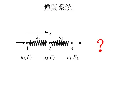
弹簧有限元分析ppt课件
- 格式:ppt
- 大小:1.31 MB
- 文档页数:8

钢板弹簧刚度特性的有限元分析newmaker1 前言钢板弹簧是汽车中广泛应用的弹性元件,刚度是其重要的物理参量。
因此,在产品试制出来之前,如何更准确的计算其实际刚度就成为大家共同关心的问题。
传统的计算方法,如“共同曲率法”和“集中载荷法”等均存在一定的局限性,在计算中往往需要加入经验修正系数来调整计算结果。
随着计算机的发展,有限元法因其精度高、收敛性好、使用方便等优点逐渐被应用到板簧的设计中。
邹海荣等应用有限元法分析了某渐变刚度钢板弹簧的异常断裂问题,提出了避免此种断裂的改进措施。
胡玉梅等针对某汽车后悬架的钢板弹簧应用Ansys 软件分析了其静态强度特性,给出了钢板弹簧在不同载荷作用下的应力分布,计算结果与试验符合的较好。
谷安涛则讨论了应用有限元法设计钢板弹簧的一般流程,给出了设计的示例。
有限元法的最大优点之一就是可以仿真设计对象的实际工作状态,因而可以部分代替试验,指导精确设计。
汽车钢板弹簧存在非线性和迟滞特性。
应用有限元法进行分析时需要考虑大变形及接触,即需要同时考虑几何非线性和状态非线性,这将使得计算不容易收敛,因而需要较高的求解技巧及分析策略。
本文采用Nastran的非线性分析模块分析了某钢板弹簧的刚度特性,讨论了摩擦对其性能的影响,其分析流程及结果可以为同类型产品的设计提供参考。
2 钢板弹簧刚度的计算方法传统的计算方法有“共同曲率法”和“集中载荷法”。
此外,国内学者郭孔辉针对共同曲率法中存在的固有缺陷,提出了一种称为主片分析法的计算方法,田光宇等则针对集中载荷法的固有缺陷,提出了改进的集中载荷法。
这些方法的出发点都是把板簧各片看成是等截面的悬臂梁,不考虑板簧各片之间的摩擦和板簧变形过程中的大变形特性,采用经典梁公式计算第1叶片的端点挠度,进而求得板簧的刚度。
2.1共同曲率法共同曲率法由前苏联的帕尔希洛夫斯基提出,其基本假设为板簧受载后各叶片在任一截面上都有相同的曲率,即把整个板簧看成是一变截面梁,由此推出对称板簧的刚度计算公式如下:2.2集中载荷法集中载荷法的基本假设为板簧各叶片仅在端部相互接触,即假定第i片与第i-1片之间仅有端部的一个接触点,接触力为Pi,并且在接触点处两相邻叶片的挠度相等。


〖汽车理论与设计〗精品课程建设精品课程建设 福州大学机械工程及自动化学院车辆工程系图1 膜片弹簧的基本结构膜片弹簧的基本结构 案例二、离合器膜片弹簧的有限元分析 在工程技术领域,对于许多力学问题和物理问题,人们已经得到了它们应遵循的基本方程和相应的定解条件,程和相应的定解条件,但对于其中的大多数问题,但对于其中的大多数问题,但对于其中的大多数问题,由于方程某些特性的非线性性质,由于方程某些特性的非线性性质,由于方程某些特性的非线性性质,或由于或由于求解区域的几何形状比较复杂,求解区域的几何形状比较复杂,不能求得解析解。
不能求得解析解。
不能求得解析解。
对于这类问题,对于这类问题,对于这类问题,以前常常通过引入简化条以前常常通过引入简化条件,进行简化状态下的解答,进行简化状态下的解答,但过多的简化可能导致误差很大甚至是错误。
但过多的简化可能导致误差很大甚至是错误。
但过多的简化可能导致误差很大甚至是错误。
二十世纪六十年二十世纪六十年代以来,随着计算机的飞速发展和广泛应用,数值分析方法已经成为求解这类问题的主要工具,其中,有限单元法(Finite Element Method )在工程实践中已得到了广泛的认可。
)在工程实践中已得到了广泛的认可。
)在工程实践中已得到了广泛的认可。
有限单元法的基本思路是将复杂的结构视为由有限的、有限单元法的基本思路是将复杂的结构视为由有限的、简单的基本单元所组成。
简单的基本单元所组成。
这种基于离散化的数值计算方法,借助于矩阵方法与计算机相结合,几乎适用于求解所有的连续介质和场问题。
对于有限元法的原理,大家可到图书馆参阅相关书籍[1]。
在汽车设计中,与固体力学、流体力学、热力学、声学、电磁学等相关的问题都可以应用有限元法求解,并且在很多问题上已经成为汽车研发流程中重要的环节。
很多问题上已经成为汽车研发流程中重要的环节。
在下面的例子中,应用有限元法分析了离合器膜片弹簧的弹性特性。
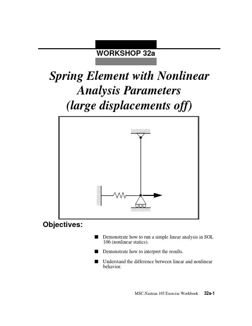
WORKSHOP 32aObjectives:s Demonstrate how to run a simple linear analysis in SOL106 (nonlinear statics).s Demonstrate how to interpret the results.s Understand the difference between linear and nonlinearbehavior.MSC.Nastran 105 Exercise Workbook32a-132a-2MSC.Nastran 105 Exercise WorkbookWORKSHOP 32a Spring Element w/ Nonlin ParamsMSC.Nastran 105 Exercise Workbook32a-3Suggested Exercise Steps:s Modify the existing MSC.Nastran input file by adding theappropriate loading conditions and nonlinear static analysiscontrol parameters.s Select Element Forces as part of the output (FORCE=ALL).s For Case Control, insert the static load set selection (LOAD)and the nonlinear static analysis parameter selection(NLPARM).s For Bulk Data, insert the relevant nonlinear static analysisparameter (NLPARM).s Prepare the model for a geometric linear static analysis (turnoff large displacements).x PARAM, LGDISP, -1s Generate an input file and submit it to the MSC.Nastransolver for a nonlinear static analysis.s Review the results.32a-4MSC.Nastran 105 Exercise WorkbookWORKSHOP 32a Spring Element w/ Nonlin ParamsInput File for Modification:prob32a.datID NAS103, WORKSHOP 32ATIME 10SOL 106 $ NONLINCENDTITLE=SIMPLE ROD SPRING - COLD ANALYSIS AND RESTART WORKSHOPSUBTITLE=GEOMETRIC NONLINEARECHO=BOTHDISP=ALLOLOAD=ALL$$ APPLY X LOAD$SUBCASE 10 $ LOAD=29.E03LABEL=APPLY LOAD P IN X DIRECTION = 29E+03OUTPUT(PLOT)SET 1 ALLMAXI DEFO 5.AXES Z, X, YVIEW 0., 0., 0.FIND SCALE ORIGIN 1 SET 1PLOT STATIC 0 MAXIMUM DEFORMATION 5. SET 1BEGIN BULKGRID, 1, 0, 0.0, 0.0, 0.0, , 23456GRID, 3, 0, 0.0, 10.0, 0.0, , 123456CROD, 3, 3, 3, 1CELAS1, 2, 2, 1, 1, 0PROD, 3, 3, .01PELAS, 2, 1.0E3MAT1, 3, 1.0E7FORCE, 1, 1, 0, 1.6E4, 1.0FORCE, 2, 1, 0, 2.4E4, 1.0FORCE, 3, 1, 0, 2.9E4, 1.0ENDDATAMSC.Nastran 105 Exercise Workbook32a-532a-6MSC.Nastran 105 Exercise WorkbookExercise Procedure:1.Users who are not utilitizing MSC.Patran for generating an input file should go to Step 12, otherwise, proceed to step 2.2.Create a new database called prob32a.db .In the New Model Preference form set the following:3.Those who do not wish to set up the model themselves may want to play the session file, prob32.ses . If you choose to build the model yourself, proceed to step 4.The model has now been created. Skip to Step 10.Whenever possible click u Auto Execute (turn off).4.Create a 10 unit long beam.File/New...New Database Name prob32aOKTolerance:q DefaultAnalysis Code:MSC/NASTRAN Analysis Type:StructuralOK File/Session/Play...Session File List prob32.sesApplyx GeometryAction: Create Object: Curve Method:XYZ Vector Coordinate List <0, 10, 0>ApplyWORKSHOP 32a Spring Element w/ Nonlin Params5.Mesh the curve with one BAR2 element.x Finite ElementsAction: CreateObject: MeshType: CurveGlobal Edge Length10Element Topology:Bar2Curve List Curve 1(Select the curve.)ApplyFor clarity, increase the node size using the following toolbar icon:6.Create the material property for the beam.x MaterialsAction: CreateObject: IsotropicMethod: Manual InputMaterial Name mat_1Input Properties...Elastic Modulus = 1.E7ApplyCancel7.Create the property for the beam.x PropertiesAction: CreateMSC.Nastran 105 Exercise Workbook32a-732a-8MSC.Nastran 105 Exercise Workbook8.Create a grounded spring at the bottom of the beam.First, create a 0-D element to be used for spring constant assignment at the bottom of the beam.Next, create the grounded spring property for the newly created element.Dimension: 1D Type:Rod Property Set Name prop_1Input Properties...Material Name m:mat_1Area 0.01OKSelect Members Curve 1(Select the curve.)Add Apply x Finite ElementsAction: Create Object: Element Method: Edit Shape:Point Topology:Point Node 1 =Node 1(Select the bottom node.)Applyx PropertiesAction: Create Object: 0DMethod:Grounded SpringWORKSHOP 32aSpring Element w/ Nonlin ParamsMSC.Nastran 105 Exercise Workbook 32a-9You can either type in the point element into the databox or click on the point itself. This is done by first, clicking the Select Members databox and then clicking on the following icon.9.Create the Loads/BCs for the model.First, fix the top end of the beam.Property Set Name prop_2Input Properties...Spring Constant 1.E3Dof at Node 1UX OKSelect Members:Elm 2(Select the point element previously created.)Add Apply x Loads/BCsAction: Create Object: Displacement Method: Nodal New Set Name constraint_1Input Data...Translation < T1 T2 T3 >< 0, 0, 0 >Rotation < R1 R2 R3 >< 0, 0, 0 >OKSelect Application Region...Point Element32a-10MSC.Nastran 105 Exercise WorkbookNext, create the guided support Load/BC at the base (free in x-direction, and fixed in all other DOFs).10.Create the loading for the model.For this analysis model, the load will be incremented up to the final load in a single subcase.Select Geometry Entities:Point 2(Select point at top of beam.)Add OK ApplyNew Set Name:constraint_2Input Data...Translation < T1 T2 T3 >< , 0, 0 >Rotation < R1 R2 R3 > < 0, 0, 0 >OKSelect Application Region...Select Geometry Entities Point 1(Select point at bottom of beam.)Add OK Apply x Loads/BCsAction: Create Object: Force Method: Nodal New Set Name load_3Input Data...Force <F1 F2 F3><29.E3, 0, 0>OKWORKSHOP 32aSpring Element w/ Nonlin ParamsMSC.Nastran 105 Exercise Workbook 32a-11Your viewport should now appear as follow:11.Now you are ready to generate an input file for analysis.Click on the Analysis radio button on the Top Menu Bar and set up the subcases as follows:Select Application Region...Select Geometry Entities Point 1(Select point at bottom of beam.)Add OK Applyx AnalysisAction: Analyze Object: Entire Model Method: Analysis Deck Job Nameprob32a32a-12MSC.Nastran 105 Exercise WorkbookAn input file called prob32a.bdf will be generated. This process of translating your model into an input file is called the Forward Translation. The Forward Translation is complete when the Heartbeat turns green. MSC.Patran users should now proceed to Step 13.Solution Type...Solution Type:q NONLINEAR STATIC Solution Parameters...(Turn off large displacements.)Ë Large DisplacementsOK OKSubcase Create...Available Subcases:DefaultSubcase Parameters...Number of Load Increments:4OKOutput Requests...Output Requests:STRESS(SORT1...DeleteOutput Requests:SPCFORCES(SORT1...DeleteSelect Result Type:Element Forces OK Apply Cancel ApplyWORKSHOP 32aSpring Element w/ Nonlin ParamsMSC.Nastran 105 Exercise Workbook 32a-13Generating an input file for MSC.Nastran Users:12.MSC.Nastran users can generate an input file using the data from the Model Description. The result should be similar to the output below (prob32a.dat ):ASSIGN OUTPUT2 = ’prob32a.op2’ , UNIT=12ID NAS103, WORKSHOP 32A SOLUTION TIME 10SOL 106 $ NONLIN CENDTITLE=SIMPLE ROD SPRING - COLD ANALYSIS AND RESTART WORKSHOP SUBTITLE=GEOMETRIC NONLINEAR ECHO=BOTH DISP=ALL OLOAD=ALL FORCE=ALL$$ APPLY X LOAD $SUBCASE 10 $ LOAD=29.E03LABEL=APPLY LOAD P IN X DIRECTION = 29E+03 LOAD=3 NLPARM=10OUTPUT(PLOT) SET 1 ALL MAXI DEFO 5. AXES Z, X, Y VIEW 0., 0., 0.FIND SCALE ORIGIN 1 SET 1PLOT STATIC 0 MAXIMUM DEFORMATION 5. SET 1BEGIN BULK PARAM, POST, -1PARAM, PA TVER, 3.0GRID, 1, 0, 0.0, 0.0, 0.0, , 23456GRID, 3, 0, 0.0, 10.0, 0.0, , 123456CROD, 3, 3, 3, 1CELAS1, 2, 2, 1, 1, 0PROD, 3, 3, .01PELAS, 2, 1.0E3MAT1, 3, 1.0E7FORCE, 1, 1, 0, 1.6E4, 1.0FORCE, 2, 1, 0, 2.4E4, 1.0FORCE, 3, 1, 0, 2.9E4, 1.0PARAM, LGDISP,-1NLPARM, 10, 4ENDDATA32a-14MSC.Nastran 105 Exercise WorkbookWORKSHOP 32aSpring Element w/ Nonlin ParamsMSC.Nastran 105 Exercise Workbook 32a-15Submit the input file for analysis:13.Submit the input file to MSC.Nastran for analysis.13a.To submit the MSC.Patran .bdf file, find an availableUNIX shell window. At the command prompt enter nastran prob32a.bdf scr=yes . Monitor the analysis using the UNIX ps command.13b.To submit the MSC.Nastran .dat file, find an availableUNIX shell window and at the command prompt enter nastran prob32a.dat scr=yes . Monitor the analysis using the UNIX ps command.14.When the analysis is completed, edit the prob32a.f06 file and search for the word FATAL . If no matches exist,search for the word WARNING . Determine whether existing W ARNING messages indicate modeling errors.14a.While still editing prob32a.f06, search for the word:D I S P L A C E (spaces are necessary).What is the x-displacement of the guided end at the end of the analysis?What is the force in the spring element at the end of the analysis?T1 =FORCE =Comparison of Results:pare the results obtained in the .f06 file with theresults on the following page:32a-16MSC.Nastran 105 Exercise Workbook32a-18MSC.Nastran 105 Exercise Workbook16.This ends the exercise for MSC.Nastran users.MSC.Patran users should proceed to the next step.17.Proceed with the Reverse Translation process, that is, importing the prob32a.op2 results file into MSC.Patran. To do this, return to the Analysis form and proceed as follows:18.When the translation is complete bring up the Results form.Now we will generate the fringe plot of the model.Now click on the Select Results icon.x AnalysisAction: Read Output2Object: Result Entities Method:TranslateSelect Results File...Selected Results File prob32a.op2OK Apply x Results Action: Create Object:FringeSelect Result Case(s) Default, PW Linear: 100.% of LoadSelect Fringe Result Displacements, Translational Quantity:MagnitudeWORKSHOP 32aSpring Element w/ Nonlin ParamsMSC.Nastran 105 Exercise Workbook 32a-19Next click on the Target Entities icon.Note: This feature allows you to view fringe plots of specific elementsof your choice.Click on the Display Attributes icon.For better visual quality of the fringe plot, change the width of the line. Note: The Display Attributes form allows you the ability to changethe displayed graphics of fringe plots.Now click on the Plot Options icon.The resulting fringe plot should display the displacement spectrum superimposed over the undeformed bar. The final fringe plot displaying the physical deformation of the model can be created as follows:Target Entity: Current ViewportStyle: Discrete/Smooth Display:Free EdgesWidth:(Select the third line from top.)Coordinate Transformation: None Scale Factor 1.0ApplyTarget Entities32a-20MSC.Nastran 105 Exercise WorkbookNow click on the Select Results icon.Click on the Display Attributes icon.In order to see the deformation results accurately, set the Scale Interpretation to True Scale with a Scale Factor of 1.Now click on the Plot Options icon.x Results Action: Create Object:DeformationSelect Result Case(s) Default, PW Linear: 100.% of LoadSelect Fringe Result Displacements, Translational Show As:ResultantLine Width: (Select the third line from top.)Scale Interpretation q True ScaleScale Factor 1.0s Show Undeformed Line Width:(Select the third line from top.)Coordinate Transformation: None Scale Factor 1.0ApplyWORKSHOP 32a Spring Element w/ Nonlin ParamsMSC.Nastran 105 Exercise Workbook 32a-21The resulting fringe plot should display the displacement spectrum in addition to the physical deformation of the model. The following step will combine the two previous plots into one. MSC.Patran automatically combines both the fringe and deformation plots into one.To better fit the results on the screen, zoom out a couple times using the following toolbar icon:Alternatively, use any number of the toolbar icons to better view the resulting fringe plot.Your viewport should now contain the following image:Notice that the deflection is almost 3 times the length of the beam!This suggests that a nonlinear analysis which accounts for large displacements is necessary to obtain a more accurate answer.To clear the post-processing results and obtain the original model in the viewport, select the Reset Graphics icon.Quit MSC.Patran when you have completed this exercise.MSC.Patran .bdf file: prob32a.bdf$ NASTRAN input file created by the MSC MSC/NASTRAN input file$ translator ( MSC/PATRAN Version 7.5 ) on January 16, 1998 at$ 08:27:27.ASSIGN OUTPUT2 = ‘prob32a.op2’, UNIT = 12$ Direct Text Input for File Management Section$ Nonlinear Static Analysis, DatabaseSOL 106TIME 600$ Direct Text Input for Executive ControlCENDSEALL = ALLSUPER = ALLTITLE = MSC/NASTRAN job created on 16-Jan-98 at 08:25:44ECHO = NONEMAXLINES = 999999999$ Direct Text Input for Global Case Control DataSUBCASE 1$ Subcase name : DefaultSUBTITLE=DefaultNLPARM = 1SPC = 2LOAD = 2DISPLACEMENT(SORT1,REAL)=ALLFORCE(SORT1,REAL,BILIN)=ALL$ Direct Text Input for this SubcaseBEGIN BULKPARAM POST -1PARAM PATVER 3.PARAM AUTOSPC NOPARAM COUPMASS -1PARAM K6ROT 100.PARAM WTMASS 1.PARAM LGDISP -1PARAM,NOCOMPS,-1PARAM PRTMAXIM YESNLPARM 1 4 AUTO 5 25 PW NO + A+ A .001 1.-7$ Direct Text Input for Bulk Data$ Elements and Element Properties for region : prop_1PROD 1 1 .01CROD 1 1 1 2$ Elements and Element Properties for region : prop_2PELAS 2 1000.CELAS1 2 2 1 132a-22MSC.Nastran 105 Exercise WorkbookWORKSHOP 32a Spring Element w/ Nonlin Params$ Referenced Material Records$ Material Record : mat_1$ Description of Material : Date: 19-Jun-97 Time: 15:12:40MAT1 1 1.+7$ Nodes of the Entire ModelGRID 1 0. 0. 0.GRID 2 0. 10. 0.$ Loads for Load Case : DefaultSPCADD 2 1 3LOAD 2 1. 1. 1$ Displacement Constraints of Load Set : constraint_1SPC1 1 123456 2$ Displacement Constraints of Load Set : constraint_2SPC1 3 23456 1$ Nodal Forces of Load Set : load_3FORCE 1 1 0 29000. 1. 0. 0.$ Referenced Coordinate FramesENDDATA c9d4ca67MSC.Nastran 105 Exercise Workbook32a-2332a-24MSC.Nastran 105 Exercise Workbook。