XH-MC-1使用指南
- 格式:pdf
- 大小:403.63 KB
- 文档页数:13
税控发票开票软件发票信息数据接口规范V4.01概述为进一步优化纳税服务,满足纳税人内部管理信息系统与增值税发票税控开票软件的衔接需要,国家税务总局下发了税控发票开票软件发票信息数据接口规范V1.0、V2.0、V3.0版。
随着增值税发票管理新系统的全国推广和营改增的全面实施,公布的接口已经不能满足需要,现对该接口进行更新升级,形成V4.0版。
本接口规范适用于是增值税发票税控开票软件(金税盘版)与增值税发票税控开票软件(税控盘版)的商品编码版本(以下统一简称为税控发票开票软件),配合手工导入开具、自动导入开具和发票明细导出功能使用。
2接口说明2.1待开发票信息导入接口通过税控发票开票软件中的手工导入开具和自动导入开具功能,将待开发票的信息批量导入到税控发票开票软件,完成发票开具。
选择手工导入开具时,首先选择要导入的XML文件,再对导入发票信息逐张开具并打印发票。
选择自动导入开具时,首先设置文件存储路径和轮询时间。
自动导入开具功能开启后,系统自动轮询指定路径下的XML文件,自动完成发票开具,并将开具结果写入指定文件目录。
2.2已开发票信息导出接口通过税控发票开票软件中的发票明细导出功能,实现已开发票信息的批量导出,生成EXCEL文件或XML文件。
3接口定义本接口规范内容包括待开发票信息导入接口和已开发票信息导出接口,发票类型为增值税专用发票、增值税普通发票、货物运输业增值税专用发票、机动车销售统一发票和二手车销售统一发票。
3.1增值税专用发票和增值税普通发票3.1.1修改说明单据新增了Version节点,增加商品编码功能后的版本为2.0;单据新增了Spbmbbh节点,增加商品编码功能后为税局下载的商品编码表版本号;单据新增了Hsbz节点,用于区分营改增新增的5%不含税税率和中外合作油气田(原海洋石油)5%税率、1.5%税率、差额税;单据商品明细中新增了Spbm(商品编码)、Qyspbm(企业商品编码)、Syyhzcbz(享受优惠政策)、Lslbz(零税率标识)、Yhzcsm(优惠政策说明),详细内容请查看接口规范中相关说明;单据只允许对单行商品进行折扣,折扣行紧挨被折行之后,折扣行的商品名称与被折行相同;单据新增了Kce节点,用于差额税计算。
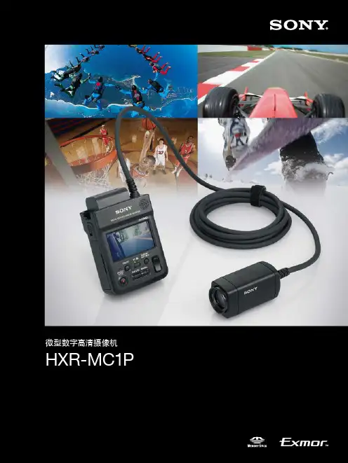
微型数字高清摄像机HXR-MC1PSony 自豪地推出了一款别具匠心的高清摄像机 HXR-MC1P ,为视频制作领域添上了完美的一笔。
HXR-MC1P 是一款使用简便的摄像机,它包括一个小型摄像单元以及一个带有液晶屏和记录功能的控制单元。
使用这款多合一的小型摄像机时,无需使用其他设备,只需随身携带就可随时进行拍摄。
而且,摄像机单元采用了放溅水设计,可以在苛刻的环境中使用,比如在户外或水边拍摄。
它的结构很简单,能够将您的拍摄环境大大拓宽。
此外,HXR-MC1P 独有的外形设计使它可以在特别的环境和角度下进行拍摄,如从运动员的视角拍摄体育比赛,在赛车运动中从车内进行拍摄等。
它的主单元装有液晶屏,拍摄开始后,用户可以立即对拍摄素材进行检查。
更多的应用领域,等待着用户自己去开发和体验。
微型数字高清摄像机HXR-MC1P34赛车运动使用HXR-MC1P ,您可以拍摄出令人称奇的绝妙镜头 赛道在你眼前快速穿梭,就好像自己亲自驾驶摩托车或赛车在赛道上飞驰一样。
HXR-MC1P 的体积非常小,可以在赛车车身上灵活地安装。
通过使用选购的广角转换镜头,甚至可以在狭窄的赛车内部进行拍摄。
现场延迟/记录HXR-MC1P 的控制单元装有HDMI 输出和模拟符合视频输出接口。
使用一个可另购的HDMI/HD-SDI 转换器或一个模拟/数字转换器,还可以使用HD-SDI 信号制作现场延迟护记录。
如果您近距离拍摄画面,如将HXR-MC1摄像机安装到足球球门柱上,或拍摄音乐家手部的近景,可获得更加动人的画面。
将HXR-MC1的记录模式设为“标清”时,HDMI 和模拟视频接口可输出标清信号。
拍摄小动物和昆虫HXR-MC1P 摄像机还非常适合于拍摄小动物和昆虫。
它的体积小巧,可以在野外小心地拍摄动物。
它的连续记录时间长达405分钟左右(6小时45分钟)*。
将摄像机在草丛中滑过,就可以拍摄到奇妙的昆虫世界。
* 使用选购的NP-FH100电池连续进行拍摄(液晶屏背光灯关闭)。
XMH系列智能手动操作器使用说明书一、概述XMH系列操作器采用了多项国际先进技术,具备宽范围输入100~240VAC的开关电源,输入采用数字校正及自校准技术,测量精确稳定,消除了温漂和时漂引起的测量误差。
仪表全面采用了表面贴装工艺,并采用了多重保护和隔离设计,抗干扰能力强、可靠性高。
可直接输入各类阀位给定信号,输出电压或电流控制信号,或直接取代伺服放大器,输出正转、反转控制信号,驱动有反馈(或无反馈)的电动执行器,适合作为DCS系统回路调节控制输出和智能调节器控制输出的备用操作器使用。
可同时输入和显示给定信号和反馈信号,并同时输出控制信号和一路变送输出;具有手动/自动无扰切换进行控制功能。
并配合各种执行器对电加热设备和电磁、电动阀门控制、报警控制、数据采集。
双4位LED数字显示反馈值(或给定信号)和输出信号,可选双模拟光柱显示输出值和反馈值。
本系列仪表最多可选配两个上限报警、一个下限报警继电器输出功能。
当直接驱动阀门手动控制时,为硬手操功能。
并且具有手动状态继电器输出功能。
二、技术规格输入信号:控制输入信号:热电偶,K、S、E、J、T、B等;热电阻,Pt100、Cu50等;0~80Ω、0~400Ω、0~20mV、0~100mV、0~1V、0.2~1V、4~20mA、0~20mA、特殊规格(请定货时注明)反馈输入信号:电流、电压、电阻显示范围:-1999 ~ 9999测量精度:0.2级报警功能:上下限报警。
输出规格: 继电器:触点开关输出(常开+常闭),触点容量220VAC/2A或24VDC/2A。
W1模块:无触点开关输出(常开),触点容量220VAC/200mA。
电 流:4~20mA、0~20mA、0~10mA。
电 压:0~5V、1~5V变送输出:4~20mA、0~20mA(负载电阻≤250Ω),0~10mA(负载电阻≤500Ω),0~5V,1~5V(负载电阻≥200KΩ)变送精度:0.3级(±0.3%FS)。

苹果电脑使用全攻略本人使用苹果机也有一段时间了,积累了一些东西与大家分享,同时也为了更多的人少走弯路,让大家了解苹果并且使用苹果,我写了以下内容。
如果内容有误,请大家指出。
一:苹果电脑的一些基本概念(1)苹果电脑使用的操作系统是MAC OS X ,最新的版本代号是Tiger。
她是基于开放源码的Darwin UNIX计划, 也就是说MAC OS X实际上是一个UNIX操作系统, UNIX向来以工作稳定效率高但是难于学习著称, 苹果MAC OS X利用了UNIX系统稳定高效的特点, 又通过自己专门设计的Aqua操作界面完美地解决了易用性问题,使OS X成为最易用的操作系统之一。
(2)MAC OS X与windows的主要区别是:windows程序不能在苹果机上直接运行, 因为苹果机的CPU是PowerPC,运行windows软件需要通过虚拟机来模拟,而且模拟效率不好, 所以不推荐, 建议应急用。
(3)Apple Care,苹果维护保修,别名:苹果保鲜。
苹果公司提供的苹果保鲜是全球性有效!购买全新苹果电脑产品,苹果公司提供一年有限责任的苹果全球维护保修保证。
自带的一年期有限责任苹果维护保修保证完结之前,可于当地认可的苹果代理经销商,自行购买二年期限的有限责任苹果维护保修保证。
苹果保鲜适用于任何型号的苹果电脑和配套液晶显示器。
(4)苹果有微软为其开发的OFFICE软件,最新的版本是OFFICE 2004,她包括word,po erpoint,excel,m sn,virtual pc。
因此苹果在文字处理方面没有任何的不方便。
苹果也有QQ,国内的苹果爱好者自己开发了两个QQ软件:渤麦堂的ISQ和清华版的IQQ,但是这里没有QQ游戏,功能也仅限于文字聊天。
(5)由于苹果使用UNIX内核,因此苹果机非常稳定。
并且苹果机的保有量比较少,病也主要是针对windows系统,目前来讲,苹果病毒几乎没有。
(6)苹果操作系统没有英文版与中文版之分,她是多国语言的操作系统,可以任意调,非常适合学习外文。
4-121-565-21(1)高清晰度数字摄录一体机操作指南在操作本机之前,请先通读本手册,然后将其妥善保存以备日后参考HXR-MC1P© 2009 Sony Corporation2操作摄像机前请先阅读此手册在操作本机之前,请先通读本手册,然后将其妥善保存以备日后参考。
在电脑上处理摄像机录制的图像请参阅储存在附送的CD-ROM 上的“PMB (Picture Motion Browser) 指南”。
本摄像机可使用的“Memory Stick”类型•录制动画时,建议使用带有以下标记的1 GB 或更大的“Memory Stick PRO Duo”:–(“Memory StickPRO Duo”)*–(“Memory Stick PRO-HG Duo”)*您可使用带有或者不带Mark2的“Memory Stick PRO Duo”。
•关于“Memory Stick PRO Duo”的可录制时间,请参阅第15页。
“Memory Stick PRO Duo”/“MemoryStick PRO-HG Duo”(该尺寸可用于本摄像机。
)“Memory Stick”(无法在本摄像机中使用。
)•“Memory Stick PRO Duo”和“MemoryStick PRO-HG Duo”在本手册中统称为“Memory Stick PRO Duo”。
•除上述存储卡外,不得使用任何其它类型的存储卡。
•“Memory Stick PRO Duo”只能用于“Memory Stick PRO”兼容装置。
•请勿在“Memory Stick PRO Duo”或“Memory Stick Duo”转接器上贴标签或类似物。
•当在“Memory Stick PRO”兼容装置上使用“Memory Stick PRO Duo”时,请将“Memory Stick PRO Duo”插入“Memory Stick Duo”转接器。

第9卷第3期2011年5月生 物 加 工 过 程Ch i nese Journa l o f B ioprocess Eng i neer i ng V o.l 9N o .3M ay 2011do:i 10.3969/.j issn .1672-3678.2011.03.014收稿日期:2010-11-14基金项目:国家自然科学基金资助项目(30800864)作者简介:董庆利(1979)),男,山东临沂人,副教授,研究方向:畜产品安全与质量控制,E-m ai:l dongq i ngl@i 126.co m冻结猪肉解冻措施筛选及优化董庆利,黎园园,梁 娜,茅琼迪(上海理工大学医疗器械与食品学院,上海200093)摘 要:为了较好地保持冻结猪肉解冻后的品质,对冻结猪肉采用空气解冻、超声波解冻和微波解冻处理,研究其对解冻猪肉品质的影响,并对较好的解冻方法进行工艺优化。
研究结果表明:3种解冻方法中,微波解冻能较好地保持解冻猪肉的品质。
对微波工艺进行温度和间歇时间的优化,结果显示采用25e 微波解冻处理10m in 后间歇10m in 交替进行的解冻方法较好。
关键词:冻结肉;解冻;微波;超声波;优化中图分类号:TS25114 文献标志码:A 文章编号:1672-3678(2011)03-0066-05Selection and optim izati on of tha w i ng treat ment for the frozen porkDONG Q i n g l,i L I Yuanyuan ,LI A NG N a ,MAO Q iongdi(Schoo l ofM edical Instru m en t and Food Eng i neer i ng,U niversity of Shanghai f o r Sc i ence and T echno logy,Shangha i 200093,Chi na)Abst ract :To keep t h e qua lity o f tha w ed pork ,t h a w i n g treat m ent for the frozen po r k by a ir ,u ltrasonic w ave and m icro w ave treat m en ts w ere i n vesti g ated ,and the effect of t h a w i n g process w as st u died on t h e qua lity o f tha w i n g pork .M oreover ,processi n g o f t h e tha w i n g treat m ent w as also opti m ized .The results i n dicated t h at the m icro w ave treat m en tw as the be tterm ethod for tha w i n g pork than the air and m icro w ave treat m ents .Further opti m ization sho w ed that the tha w ed po r k qua lity w as i m proved by keepi n g m icro w ave tha w i n g for 10m i n w ith inter m ittent of 10m i n at 25e .K ey w ords :fr o zen por k ;tha w ;m icro w ave ;u ltrason ic w ave ;opti m izati o n 畜禽在屠宰后的冷冻处理是其贮藏和流通的重要形式,冻结肉也是当前肉类主要的消费形式之一。
HXM-1 Hx Series Microphone Preamplifier User’s Guide The Hx Series from Demeter Amplification is a revolutionary approach in tube design utilizing innova -tive tube circuitry for the amplification functions and the latest in solid state for the driver functions. All Hx Series equipment use the finest quality components featuring metal film resistors, high quality film capacitors, and custom toroidal power transformers housed an attractive aluminum and steel single space rack mount case. All units feature fully regulated power supplies supplying 200V to the tubes and + and - 18V for the solid state components, giving all Hx series components tremendous head room up to +28 dB output into 600 ohms.The HXM-1 is a two channel microphone preamplifier utilizing Jensen transformers and the revolution -ary Hx Series tube amplification circuitry. Each channel has variable gain (30 to 60 dB) instrument input, low cut, phase, pad, overload indicator, volume, 48V phantom and 10 section VU with selectable sensi -tivity.INPUTS, CONTROLS AND FEATURESCH Input: instrument level input used to amplify guitars, keyboards etc. to line level. This input turns the microphone preamplifier into a tube direct box.Low Cut: this switch inserts a 6 dB per octave low cut filter starting around 200 Hz and is down -12 dB at 40 Hz. The slow slope reduces phase shift.Microphone Pad: this switch inserts a 20 dB pad in front of the Jensen microphone transformer; it is used to prevent overload distortion (red LED above) when the gain control cannot. it also prevents the transformer from saturating. Overload is indicated by the red LED above the switch.Phantom: this switch turns on the 48V phantom power to microphones requiring it. This switch should not be turned on for dynamic microphones or other microphones that do not require it. It should not be turned on for any microphones plugged into the 1/4” TRS inputs in the back of the unit or damage to microphone may result. Phantom on is indicated by the yellow led above.Phase: this switch reverses the phase of the microphone input. It can be used to match phase of differ -ing inputs or as an effect to enhance a mixing of sources by canceling out some bass frequencies.Gain: this control changes the gain (30 to 60 dB) of the tube preamplifier by controlling the amount of feedback going to the tube. The gain should be set at the lowest setting that will still produce a usable signal level. It should not be set too high or the unit will overload (red LED) and distort. If turning down the gain does not stop overloading, use the microphone pad switch. It is OK for the overload LED to flicker occasionally.6990 Kingsbury Road | Templeton, CA 93465 | 805-461-4100 | /HXM-1 Hx Series Microphone Preamplifier User’s Guide Volume: this control is a fader between the tube microphone preamplifier and the balanced line driver. It’s setting does not effect overload. It should be set near its maximum setting and used only for fine tuning signal level or for fades in or out.Meter: this switch controls the sensitivity of the VU LEDs and is calibrated for +4 dB out and -10 dB in.Overload: this LED indicates if the signal level of the tube amplifier is near reaching its distortion level. it is set to start flickering 6 dB before distortion is reached. A little flickering is fine. The gain must be lowered or Microphone Pad engaged if the LED is constantly on.Phantom LED: this yellow LED indicates that phantom power is being provided to the microphone input.VU: This row of LEDs indicate the output level going to the balanced line output jacks in standard vol -ume units. The level is indicated above each LED. There is no distortion if you go past 3 VU. The micro -phone preamplifier has over 18 dB more headroom above the meter’s highest indication.REAR PANELVoltage Selector: selects mains voltage 115 volts U.S.A. and 230 volts for Europe. WARNING: damage to this equipment will occur if this switch is improperly set.Fuse:******************************************.Output: balanced three pin XLR connector and balanced TRS 1/4” phono jacks. WARNING: do not hook up output connectors to any inputs that have 48 volt phantom appearing on them. This will damage the units output circuitry.Input: balanced Jensen transformer inputs on both three pin XLR and TRS 1/4” phono jacks. WARNING: turn off 48 volt phantom when using TRS 1/4” jacks. Damage will occur to the microphone when using unbalanced microphone input cables.HOOKUP TIPS1. Make sure that the tube microphone preamplifier is connected to inputs that are designed to operate at line level, otherwise distortion could result.2. Avoid ground loops. If hum occurs it may be necessary to telescope some grounds. This is done by cutting the ground wire on only one side of the three pin XLR connector.3. Keep wiring short and neat.4. Make sure AC grounds are properly connected.5. Don’t hesitate to call the factory or your Demeter dealer with any questions. We are here to help.6990 Kingsbury Road | Templeton, CA 93465 | 805-461-4100 | /。
FLASH PRODUCTSELECTION GUIDESerial NOR Flash Memory Parallel NOR Flash Memory NAND Flash MemoryMacronix International Co., Ltd.16, Li-Hsin Road, Science Park, Hsinchu, Taiwan Tel: +886-3-578-6688Fax: +886-3-563-2888Macronix International Co., Ltd.19F, 4, Min-Chuan E. Road, Sec. 3, Taipei, Taiwan Tel: +886-2-2509-3300Fax: +886-2-2509-2200Macronix (Hong Kong) Co., Limited, SuZhou Office No. 55, Su Hong Xi Rd, SuZhou Industrial Park,SuZhou China 215021Tel: +86-512-6258-0888Fax: +86-512-6258-6799Macronix (Hong Kong) Co., Limited, ShenZhen Office Room 1401, Block A Tian An Hi-Tech Plaza Tower CheGongMiao Futian District Shenzhen 518040 PRC Tel: +86-755-8343-3579Fax: +86-755-8343-8078Macronix (Hong Kong) Co., Ltd.702-703, 7/F, Building 9, Hong Kong Science Park, 5 Science Park West Avenue, Sha Tin, N.T.Tel: +852-2607-4289Fax: +852-2607-4229Macronix Pte. Ltd.1 Marine Parade Central #11-03 Parkway Centre Singapore 449408Tel: +65-6346-5505Fax: +65-6348-8096Macronix Asia Limited.NKF Bldg. 5F, 1-2 Higashida-cho, Kawasaki-ku Kawasaki-shi, Kanagawa Pref. 210-0005, Japan Tel: +81-44-246-9100Fax: +81-44-246-9105Macronix Asia Limited.#906, 9F, Kangnam Bldg., 1321-4, Seocho-Dong, Seocho-Ku,135-070, Seoul, Korea Tel: +82-2-588-6887Fax: +82-2-588-6828Macronix America, Inc.680 North McCarthy Blvd. Milpitas, CA 95035, U.S.A.Tel: +1-408-262-8887Fax: +1-408-262-8810Macronix Europe N.V.Koningin Astridlaan 59, Bus 1, 1780 Wemmel, Belgium Tel: +32-2-456-8020Fax: +32-2-456-8021Copyright© Macronix International Co., Ltd. 2011-2012. All rights reserved, including trademarks and tradename thereof, such as Macronix, MXIC, MXIC Logo, MX Logo, Integrated Solutions Provider, NBit, NBiit, Macronix NBit, eLiteFlash, XtraROM, Phines, KH Logo, BE-SONOS, KSMC, Kingtech, MXSMIO, Macronix vEE, Macronix MAP, Rich Audio, Rich Book, Rich TV, and FitCAM. The names and brands of third party referred thereto (if any) are for identification purposes only.Except for specially designed product, Macronix' products shall not be used for applications relating to nuclear facility, military, life saving, life sustaining, aircraft, or systems where failure or malfunction may result in personal injury.JANUARY. 2012MACRONIX23SERVICEMacronix is committed to providing reliable and stable support to satisfy customers' expectation for a long-lasting partnership. Macronix customers are served by efficient global logistic coverage, a dedicated service team, a dependable product roadmap, and innovative technology for next generation requirements.MANUFACTURINGMacronix has over 20 years of IDM experience with manufacturing excellence and in-house design capabilities which facilitate continuous improvement processes in all aspects of the development and production cycle. We provide high quality parts that make driving more reliable, comfortable and eco-friendly; this is our passion and common goal that we share with our customers.QUALITYOur stringent quality standards, based on the ISO 9001 philosophy, have resulted in TS16949 certification. With the mind-set of building up a responsible business, Macronix is ISO14001(Environmental Management), IECQ QC 080000(Hazardous Substances Management), and SA 8000(Social Accountability Management) certified. Our Green Product Management system has been highly recognized by our customers, thereby, Macronix is SONY's Green Partner, and has green partnership approvals from Nintendo, Samsung, LG and Canon. All Macronix products do not use the so called "Conflict Metals" as the raw materials; and our products are ROHS compliant, Halogen-Free, Phthalate-Free, and are free of SVHC (Substances of Very High Concern). Macronix has a well- run program working with our supply chain partners to fully comply with green product requirements.ABOUT MACRONIXMacronix, the leading provider of innovative Non-Volatile Memory (NVM) semiconductor solutions, is the largest supplier of ROM products and Serial NOR Flash worldwide. The company currently produces a wide range of ROM, NOR Flash and NAND Flash memories across various densities in embedded, consumer, enterprise, wireless, and automotive applications. Flash products are also available in packages with a small footprint and thin profile for space- constrained applications.Macronix is one of the few IDM companies worldwide with complete capabilities of Design, Manufacturing and Marketing with own Brand. Macronix dedicates itself to developing top-notch home-grown technologies and improving its manufacturing capability to offer its customers high quality products and services.MACRONIX hAS RECEIVEd• Green Product Certifications from well-known electronics companies • Social Accountability Management SA 8000 Certificate • ISO 14064 GreenHouse Gases Emissions VerificationS e r i a l F l a S hSerial FlaShSerial Flash Function ListDeviceFunction 3V 1.8V xx05xx06Exx08Dxx08Exx25Cxx26Exx33Exx35D 1635E12835E/25835Exx36D8036E/1636E6436E/12836Exx37Dxx45Exx55EU2033E/4033E/8033EU1635EH/W ACC Pin ●H/W Hold# Pin ●●●●●●●1I/O (1-1-1) ●●●●●●●●●●●●●●●●●●1I/2O (1-1-2)*●●●●●●2I/O (1-2-2)**●●●●●●●●●●●●1I/4O (1-1-4)**●●●4I/O (1-4-4)**●●●●●●●●●●QPI (4-4-4)**●DTR function●●BPx Bits (NVM)●●●●●●●●●●●●●●●●BPx Bits (SRAM)●●WPSEL Mode(BPx mode individual WP mode)●●●●●●Security Function (BPG, read lock)●Security OTP & Register ●*●●●●●●●●●●●●●●Unique ID ●●CP mode ●●●●●●●●VI/O●Note* 4Mb/2Mb None** I/O Nomenclature defined in Command, Address (Input), Data (Output) Configuration For eg: 1-1-1 denotes 1-Command, 1-Address (Input), 1-Data (Output)Serial Flash Portfolio Table512Kb1Mb 2Mb 4Mb 8Mb 16Mb 32Mb 64Mb 128Mb 256Mb3VMX25Lxx05/06Standard Serial Interface ●●●●●●●●MX25Lxx08Unique ID series●●●MX25Lxx25/26Default Lock Protection series ●●●●MX25Lxx35/36/45MXSMIO ® &MXSMIO ® Duplex series ●●●●●●MX25Lxx55MXSMIO ® Secure series ●●●●●2.5VMX25Vxx05/06Standard Serial Interface ●●●●MX25Vxx35MXSMIO ® series ●●1.8VMX25Uxx35/33MXSMIO ® series●●●●●●●3V Serial Flash Family:S e r i a l F l a S hSerial FlaSh3V MXSMIO ® & MXSMIO ®Duplex Family:2.5V Serial Flash Family: Standard Serial Interface Series92.5V Serial Flash Family: MXSMIO® Series:1.8V MXSMIO® Family:ApplicationsSegment Application 512Kb1Mb2Mb4Mb8Mb16Mb32Mb64Mb128Mb256MbComputerMobile PC●●●●●DeskTop PC●●●●Server●●●●●Printer●●●●●Graphics●●●HDD●●●●ODD ●●●●●CommunicationDSL ●●●●Cable Modem●●●●IAD/HomeGateway●●●WiMAX●●●●IP Phone●●●AP Router●●●●●ConsumerDigital TV ●●●●Digital Audio/DAM●●●DVD Player●●●Set Top Box●●●●●●Automotive After Market/In Cabin●●●●●●●●●●SerialFlaSh Serial FlaSh1011Parallel FlaShMacronix's industry standard Parallel Flash memories offer an extensive line of 3V products from 4Mb to 1Gb densities. Macronix Flash memory provides customers with cost-effective, high performance and reliable products that offer low-power consumption and high endurance. 4Mb and 8Mb products are also offered in 4mm x 6mm BGA packages for space-constrained applications. Macronix also offers a family of 1.8V products from 4Mb to 128Mb, whereas the 16Mb and 32Mb products interface an I/O voltage of 1.8V and the 32Mb to 128Mb products are featured by AD-Mux and Burst Mode. These products are used in applications like Bluetooth, MP3 Players, GPSas well as other portable applications.Standard Read Access Page Mode Read Access the system for both read and program P a r a l l e l F l a S hOPTION :G: RoHS Compliant Q: RestrictedVcc : (3.0V-3.6V), RoHS CompliantParallel Flash ExampleMX 29GL 256 F h XF I - 90 QdEVICE :29F: 5V29LV / 29GL / 68GL: 3V 29SL: 1.8V29LA/ 29GA: Security typedENSITY :20x: 2Mb 40x: 4Mb80x: 8Mb 16x: 16Mb 32x: 32Mb 64x: 64Mb 12x: 128Mb 25x: 256Mb 51x: 512MbPACKAGE TYPE :P: PDIP M: SOP Q: PLCC T/T2: TSOPXB - 0.8 mm Ball Pitch / 0.3 mm Ball Size XC - 1.0 mm Ball Pitch / 0.4 mm Ball SizeXE - 0.8 mm Ball Pitch / 0.4 mm Ball Size XF - 1.0 mm Ball Pitch / 0.6 mm Ball Size XH - 0.5 mm Ball Pitch / 0.3 mm Ball Size GB - 0.5 mm Ball Pitch / 0.25 mm Ball Size XG - 0.8 mm Ball Pitch / 0.4 mm Ball SizeTEMPERATURE RANGE :C: Commercial(0˚C to 70˚C)I: Industrial(-40˚C to 85˚C)S : Automotive Grade 3(-40˚C to 85˚C)R: Automotive Grade 2(-40˚C to 105˚C)Q: Automotive Grade 1(-40˚C to 125˚C)SPEEd :55: 55ns 70: 70ns 90: 90ns 10: 100ns 11: 110nsBLOCK TYPE :T: Top Boot B: Bottom BootH: Uniform Sector, Highest Address Sector Protected L: Uniform Sector, Lowest Address Sector ProtectedU: VI/O=1.65 to VCC, VCC=2.7 to 3.6V, Highest Address Sector Protected D: VI/O=1.65 to VCC, VCC=2.7 to 3.6V, Lowest Address Sector ProtectedGENERATIONNaND FlaSh MeMory 17。
无张力腹股沟疝修补术可选择椎管内麻醉、局麻、区域麻醉、全麻[1],但高龄患者各重要器官衰老,常存在合并症等全身性问题,承受手术麻醉打击的能力有限,手术麻醉面临巨大风险。
今探讨超声引导下神经阻滞麻醉能否为高龄患者提供更加精确的麻醉方案,以加速患者术后康复。
1资料与方法1.1一般资料选取临沂市人民医院2019年1月—2019年6月,拟行无张力疝修补术的高龄患者90例,随机分为联合组与IINB 组各45例。
联合组选择腰硬联合麻醉,IINB 组选择超声引导下髂腹下神经和髂腹股沟神经阻滞麻醉。
其中,联合组:男26例,女19例;年龄80~96岁;BMI :23.89±3.87;美国麻醉医师协会(ASA )分级Ⅰ~Ⅲ级。
IINB 组:男24例,女21例;年龄81~95岁;BMI 24.01±3.25;ASA 分级Ⅰ~Ⅲ级。
两组一般资料差异无统计学意义(>0.05)。
该研究通过我院伦理委员会的批准,所有患者均在术前签署麻醉知情同意书。
1.2方法患者均行腹股沟无张力疝修补术。
术前8h 需禁食禁水,禁止使用药物。
进入手术室后,监血压、心电图和SpO 2,开放外周静脉通路。
术前停用抗凝血药物。
对联合组患者实施腰硬联合的麻醉,[基金项目]山东省自然科学基金(ZR2016HL15);山东省医药卫生科技发展计划项目(2016WS0229)[作者简介]公艳芳(1981-01~),女,山东平邑人,主治医师,硕士研究生,研究方向:围术期器官功能保护。
E-mail:*****************[通讯作者]李希明(1973-10~),男,山东沂水人,副主任医师,研究方向:围术期器官功能保护。
E-mail:135****************超声引导下神经阻滞麻醉在高龄无张力腹股沟疝修补术中的应用公艳芳1,2李光3李希明41青岛大学(山东青岛226021)2平邑县中医院麻醉科(山东临沂273300)临沂市人民医院3普外二科4麻醉科(山东临沂276003)(下转第219页)度是97.8%,联合组的总满意度是86.7%,IINB 组麻醉满意度显著高于联合组(<0.05)。
Color CameraWAT-MC01Operation ManualThis operation manual covers safety, camera functions, installation and the correct operating procedure for the WAT-MC01. First, we ask you to read this operation manual thoroughly, then install and operate the WAT-MC01 as advised. In addition, for future reference, we also advise safekeeping of this manual.Please contact the distributor or dealer from which the WAT-MC01 was purchased, if you do not understand the installation, operation or safety instructions laid out in this manual. Not understanding the contents of the Operation Manual sufficiently may cause damage to the camera.Guide to the Safety SymbolsThe definitions of the symbols used in this operation manual are:When you do not adhere to or take not ice of the “Danger” sign, it may lead to a serious accident such as death or injury caused byfire or electric shock.When you do not adhere to or take notice of the “Warning” sign, itmay cause severe damage such as a physical injury.When you do no t adhere to or take notice of the “Caution” sign, it may incur injury and cause damage to peripheral objects in the immediate surroundings.Cautions for SafetyThe WAT-MC01 is designed to be used safely; however, it may lead to a physical accident caused by fire and electric shock if not used correctly. Therefore, please keep and read the Cautions for safety below forprotection against accidents.• Do not disassemble and/or modify the WAT-MC01. • Do not operate the WAT-MC01 with wet hands.• Use a stabilized power adaptor designed for DC+12V ±10%, with a current capacity of more than 100mA for the WAT-MC01.The recommended voltage is DC+12V ±10%• Do not expose the WAT-MC01 to wetness or high moisture conditions.The WAT-MC01 is designed and approved for indoor use only.The WAT-MC01 is not water-resistant or waterproof. If the location of the camera is outdoors or in an outdoor like environment, we recommend that you use an outdoor camera housing.• Protect the WAT-MC01 from condensation.Keep the WAT-MC01 dry at all times during storage and operation.• Should the camera not work properly, switch off the power immediately. Then, check the camera according to the 【Problems and Trouble Shooting 】section.• Avoid the striking of hard objects or dropping the WAT-MC01.The WAT-MC01 uses high quality electrical parts and precision components.• Do not connect any power supply directly to the video out terminal of the unit.Do not connect the WAT-MC01 with any monitor using a video/power single transmission terminal. The WAT-MC01 is not designed for use with this type of equipment. We also advise you to read the operation manual of the monitor you plan to use before any connections are made.• Do not install the WAT-MC01 in a position subject to direct sunlight.Sunlight shinning directly onto the WAT-MC01 lens can cause damage to the CCD.• Select a stable place for installation of the WAT-MC01.Use a support of durable strength around an installation position on a ceiling or wall when a camera stand or tripod is used.• Do not move the WAT-MC01 with the cables connected.Before moving the WAT-MC01, always remove the video cable and power cable from the rear of the camera first.• Avoid using the WAT-MC01 near any strong electromagnetic field.After installing into main equipment, if the WAT-MC01 is exposed to electromagnetic waves causing the monitored image to become distorted, we recommend the camera be shielded by appropriate protective casing.Problems and Trouble ShootingIf any of the following problems occur when using the WAT-MC01,• An optimal picture cannot be obtained, after checking that all the cables and connections are correctly in place• Smoke or any unusual odor emerges from the WAT-MC01.• An object becomes embedded or a quantity of liquid seeps into the camera housing • M ore than the recommended voltage or/and amperage has been applied to the WAT-MC01 by mistake• Anything unusual occurring to any equipment connected to the WAT-MC01.Disconnect the camera immediately according to the following procedures:Switch off the main power supply to the camera.Remove the power and video cables connected to the WAT-MC01. Contact the distributor or dealer from which the WAT-MC01 was purchasedContentsUsing the contents figures below, check to make sure all parts are present before use.WAT-MC01Power and Video cableDescription of PartsLENS FRONT FACEThe light receiving face of the CCD camera (Dirt, water or oil deposits on the CCD will cause an unclear picture on the monitor.). ② FOCUSING ADJUSTMENT NOTCHESTwo notches for fine focusing adjustment of the lens.POWER IN/VIDEO OUTThe terminal for power input and video signal output. Use the attached Power and Video cable for this purpose.CAMERA MOUNTING HOLESSix holes (two on each side) for fixing the camera.Power SupplyUse a stabilized power adaptor designed for DC+12V ±10%, with a current capacity of more than 100mA.The wiring on the connector must be exact.Be careful not to touch the other terminal while wiring. Protect the wiring portion by using insulation tape after wiring. If the above care and attention is not adhered to, damage to the WAT-MC01 and power adaptor may occur or may cause fire. Power and Video cableMountingThe WAT-MC01 has six holes on each side for M2 thread and screws. Usethe holes if the camera needs to be fixed.Set-up and Operation1 Refer to the 【Power Supply 】 and the wiring must be exact.2 Join the video out cable with the video in cable of the monitor orperipheral equipment.3 Join the power supply using the correct procedure.4 Make sure that a picture can be seen on the monitor.5To focus, turn the lens clockwise or counterclockwise while observingthe picture on the monitor. Take care when focusing not to scratch or damage the lens.OptionTo purchase these options, please contact the distributor or dealer fromwhich you purchased the WAT-MC01.Cable with BNC, Socket and connector (CB-01)The cable with BNC/DC socket. (Cable Length: 1m)Specifications• Design and specifications are subject to change without notice.• Watec is not responsible for any inconvenience or the attendant damagesto the video and monitoring recording equipment caused by misuse, mis-operation or improper wiring of our equipment.• If for any reason the WAT-MC01 does not work properly, or if you have any questions regarding installation or operation, please contact the distributor or dealer from which it was purchased.Add.: 254-2 Nihonkoku, Daihoji, Tsuruoka- Shi,。
目录
1. 传感器使用注意事项 (2)
2. 设备的安放场所 (3)
3. 仪器简介 (4)
3.1 特点 (4)
3.2 产品规格 (4)
3.3 技术指标 (4)
4. 仪器的安装 (5)
5. 仪器操作 (6)
5.1 控制面板示意图 (6)
5.2 功能详解 (7)
6. 设备检修 (9)
7. 维修说明 (11)
8. 保修单 (11)
9. 装箱单 ................................................................................................. 1.
1.器使用注意事项
(1)接触式传感器只能用于300℃以下的实验。
(2)装卸传感器时,手持传感器航空插头操作,安装时对准插槽,插好旋紧。
无特殊原因,避免反复插拔!
(3)航空插头应保持干燥,避免与反应物接触,以免造成短路。
(4)传感器导线应尽量避免接触到腔体的任何部位(包括门)。
避免可能出现的短路、打火现象。
(5)小于50ml极性溶剂:实验时,功率不能设置过大,同时在腔体中加入负载(即盛放100ml水的烧瓶)。
如升温过慢,可适当调高功率。
(6)弱极性溶剂:实验时,应加大溶剂剂量,同时降低功率,如出现控温不稳时,请加入负载。
(7)非极性物质实验时,应加入极性溶剂或离子液体帮助反应,否则非极性物质不吸收微波,造成微波负载不匹配,损坏传感器和磁控管,出现打火现象。
(8)反应温度设定时应以反应物沸点为参考,如超过反应液的沸点,微波功率就不能自动调整,长时间反应会造成传感器损坏。
(9)传感器表面为聚四氟镀层,长期在高温环境下使用,表面镀层会变软,所以在实验完毕后,反应物未冷却时插拔传感器时要小心轻柔,实验中传感器不要插到液面下过深,避免与磁子碰撞,损坏传感器表面镀层。
(10)每次做完实验后请将传感器清洗、擦干待用。
(11)本实验仪最佳加热介质为极性物质。
当实验对象为液体时,最佳反应剂量为50~1000ml。
若需加热弱极性溶剂或小剂量(<50ml)极性溶剂,请用250ml锥形瓶盛80~125ml水置于反应仪腔体中,或者放置盛放80ml甘油的容器作为微波吸收介质,并将微波功率设置在500W以下,以防止微波负载不匹配而损坏磁控管和传感器。
(12)请使用祥鹄公司专用传感器,否则可能会对反应仪造成损坏或导致微波泄漏。
进行液体实验时如未将接触式传感器插上,系统不具有测温功能,无法进行控温,因此为了保证实验的安全性,系统将自动禁止实验进行。
插拔或清洗接触式传感器时要小心,以免破坏了传感器接头的屏蔽层导致打火。
2.设备的安放场所
(1)包装物全部取出后,将反应仪放置在水平稳定的地方;
(2)反应仪应放在通风干燥的环境下,并请避开热源、阳光直射以及蒸汽,远离易燃易爆气体、腐蚀性气体;
(3)反应仪的左右两壁以及后壁与周围墙壁之间至少留出10cm空间,并且不可除去底脚;
(4)切勿遮蔽反应仪两侧以及后壁上的通风孔;
(5)为了防止发生触电事故,请您务必保证反应仪良好接地,并最好确保额定载流量大于10A。
(6)实验室电压不稳,请用户自行配置稳压电源!
3.仪器简介
3.1特点:
祥鹄XH-MC-1型实验室微波合成反应仪将先进的微波控制技术应用于实验室的化学合成与萃取。
主要由功率可调,单片机测温控温、回流冷凝、高精度温度传感器、电磁搅拌等系统组成。
仪器采用接触式传感器快速实时测温;数码管实时显示预设温度、当前温度、反应时间,测温精度达±1℃。
该反应仪价格合理,操作简单,功能齐全,是本科教学及科研的理想工具,让您真正体验到化学合成不再是枯燥乏味的工作。
3.2产品规格:
●额定电压:AC220V±10%
●额定频率:50Hz±2%
●额定电流:8.5A
●额定输入功率:1400W
●额定输出功率:900W
●微波频率:2450MHz
●微波泄漏:<1mw/cm2
●外型尺寸:485mm×340mm×310mm
●内腔尺寸:335mm×335mm×202mm
●净重:12kg
3.3技术参数:
●工作环境温度:+5~+45℃;
●工作环境相对湿度:<80%;
●贮存环境温度:-5~+55℃;
●贮存环境相对湿度:<93%;
●测温、控温范围: 0~300℃;
●测温精度:±0.2℃;
●控温精度:±1℃
●液体实验剂量:10~1000ml(推荐在50ml以上使用,极性溶剂)
●磁力搅拌速度范围:0~1000rpm;
4.仪器的安装
实验装置的安装步骤如下:
将反应试剂加入三口烧瓶中,加入搅拌磁子,将其平稳放在聚四氟乙烯垫圈上,置于炉腔正中央。
从波导截止管顶部插入三通玻璃管与中间为24#磨口的三口烧瓶连接,连接牢固后,三通玻璃管两边的两个接口应分别接球型冷凝管和滴液漏斗。
另外,为了使整套仪器安装稳固,我们还配备了用于固定玻璃仪器的立柱与三爪试管夹。
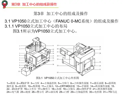
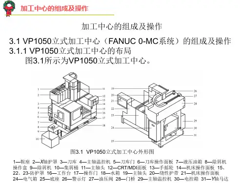
如图1所示,立柱的安装插孔位于机壳上方后部。
安装时,将立柱从插孔中插入,拧紧机身后部的三个旋钮,松紧程度应使立柱无法前后晃动为准。
立柱安装完毕后,便可将试管夹用十字转接夹固定在立柱上,然后用试管夹夹住冷凝管使其稳定。
传感器安装在反应仪腔体内,其探头穿过硅胶塞,再通过三口烧
瓶的侧口插入溶剂液面下,其信号线通过腔体侧面的接口与控制电路连接。
整体安装效果如下图所示:
XH-MC-1整体安装效果图
5.仪器操作
5.1控制面板示意图:
XH-MC-1型祥鹄实验室微波合成反应仪面板示意图(1)实时温度显示窗口;(2)预置温度显示窗口;(3)当
前时间显示窗口;(4)时间上下设定键;(5)功率调节旋
钮;(6)磁力搅拌旋钮;(7)OP1传感器通断指示灯;(8)
OP2脉冲指示灯;(9)暂停键;(10)开始键;(11)温度设
定键;(12)时间设定键;
5.2功能详解:
(1)实时温度显示窗口:接通传感器,打开电源,即有温度显示,此时该窗口显示的温度为传感器表面温度。
插入反应物开始实验后,该窗口实时显示反应物温度;
(2)预置温度显示窗口:接通传感器,打开电源,窗口显示为0.0.0.0;
(3)当前时间显示窗口:显示设定实验时间;
(4)时间上下设定键:按时间设定键,时间显示窗口0.0.0.0
闪烁,按“▲▼”键调整设定的时间;
(5)功率调节旋钮:本机型功率调节为手动调节,每向右扭一格增加100W功率,每向左扭一格减少100W功率,请用户根据反应物的极性和反应物量的大小来调节合适的微波功率。
重要提示:小于50ml极性溶剂:实验时,功率不能设置过大,同时在腔体中加入负载(即盛放100ml水或甘油的烧瓶)。
如升温过慢,可适当调高功率。
弱极性溶剂:实验时,应加大溶剂剂量,同时降低功率,如出现控温不稳时,请加入负载。
非极性物质实验时,应加入极性溶剂或离子液体帮助反应,否则非极性物质不吸收微波,造成微波负载不匹配,损坏传感器和磁控管,出现打火现象。
反应温度设定时应以反应物沸点为参考,如超过反应液的沸点,长时间反应会造成传感器损坏。
本实验仪最佳加热介质为极性物质,当实验对象为液体时,最佳反应剂量为50~1000ml。
若需加热弱极性溶剂或小剂量(<50ml)极性溶剂,请用锥形瓶盛100ml水或甘油置于反应仪腔体中,作为微波吸收介质,并将微波功率设置在600W以下,以防止微波负载不匹配而损坏磁控管和传感器;
(6)磁力搅拌旋钮:向右扭打开,根据需要调整磁力搅拌大小,请使用时用力轻柔;
(7) OP1传感器通断指示灯:接通传感器,打开电源,该灯亮;未接传感器时该灯闪烁;
(8) OP2脉冲指示灯:接通传感器,打开电源,该灯亮;进入控温阶段后该灯闪烁;
(9)暂停键:实验过程中按下此键,暂停实验;
(10)开始键:设定好温度,功率、时间等参数后按“开始”键即可开始实验;
(11)温度设定键:按温度设定键,预置温度显示窗口0.0.0.0闪烁,按“▲▼”键调整设定的温度;常按“▲”键设定速度加快;
(12)时间设定键:按时间设定键,时间显示窗口0 0:0 0 闪烁,按第一下秒开始闪烁,按“▲”键设定秒,按第二下分开始闪烁,按“▲”键设定分钟,按第三下小时开始闪烁,按“▲”键设定小时,常按“▲”键设定速度加快,最多设定时间为4小时;
6.设备检修
注意:除了有资格的维修人员之外,任何其他人员来执行拆机维修都是十分危险的,请勿自行进行任何拆卸操作。
常见问题解答:
假设实验过程中出现上述问题,请立刻切断电源,并依照上述提示加以解决。
若遇无法解决之问题,请及时与本公司技术支持联系。
7.维修说明
祥鹄实验室微波合成反应仪自售出之日起(以发票为准)主机保修12个月,传感器保修6个月,终身维修。
属下列情况之一的,不予以保修,实行收费修理:
(1)消费者因使用、维护、保管不当造成损坏的。
(2)非承担保修的修理者拆动造成损坏的;
(3)因不可抗力造成损坏的;
(4)已超过保修期限的;
8.保修单
9.装箱单。