usb3.1type-c数据线设计规范
- 格式:doc
- 大小:170.50 KB
- 文档页数:9
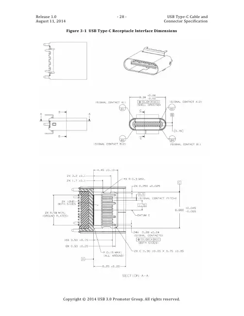
Figure 3-1 USB Type-C Receptacle Interface DimensionsFigure 3-1 USB Type-C Receptacle Interface Dimensions, cont.Figure 3-2 Reference Design USB Type-C Plug External EMC Spring Contact ZonesFigure 3-3 USB Full-Featured Type-C Plug Interface DimensionsFigure 3-4 Reference Footprint for a USB Type-C Vertical Mount Receptacle(Informative)Figure 3-5 Reference Footprint for a USB Type-C Dual-Row SMT Right AngleReceptacle (Informative)Figure 3-6 Reference Footprint for a USB Type-C Hybrid Right-Angle Receptacle(Informative)Figure 3-7 Reference Footprint for a USB Type-C Mid-Mount Dual-Row SMT Receptacle(Informative)Figure 3-8 Reference Footprint for a USB Type-C Mid-Mount Hybrid Receptacle(Informative)This specification requires that all contacts be present in the mating interface of the USB Type-C receptacle connector, but allows the plug to include only the contacts required for USB PD and USB 2.0 functionality for applications that only support USB 2.0. The USB 2.0 Type-C plug is shown in Figure 3-9. The following design simplifications may be made when only USB 2.0 is supported:∙Only the contacts necessary to support USB PD and USB 2.0 are required in the plug.All other pin locations may be unpopulated. See Table 3-5. All contacts are required to be present in the mating interface of the USB Type-C receptacle connector.∙Unlike the USB Full-Featured Type-C plug, the internal EMC springs may be formed from the same strip as the signal, power, and ground contacts. The internal EMC springs contact the inner surface of the plug shell and mate with the receptacle EMC pads when the plug is seated in the receptacle.∙ A paddle card inside the plug may not be necessary if wires are directly attac hed to the contact pins.Figure 3-9 USB 2.0 Type-C Plug Interface Dimensions3.2.2Reference DesignsThis section provides reference designs for a few key features of the USB Type-C connector. The reference designs are provided as acceptable design examples. They are not normative.3.2.2.1Receptacle Mid-Plate (Informative)The signals between the top and bottom of the receptacle tongue are isolated by a mid-plate inside the tongue. Figure 3-10 shows a reference design of the mid-plate. It is important to pay attention to the following features of the middle plate:∙The distance between the signal contacts and the mid-plate should be accurately controlled since the variation of this distance may significantly impact impedance of the connector.∙The mid-plate in this particular design protrudes slightly beyond the front surface of the tongue. This is to protect the tongue front surface from damage caused by miss-insertion of small objects into the receptacle.∙The mid-plate is required to be directly connected to the PCB ground with at least two grounding points.∙The sides of the mid-plate mate with the plug side latches, making ground connections to reduce EMC. Proper surface finishes are necessary in the areaswhere the side latches and mid-plate connections occur.Figure 3-10 Reference Design of Receptacle Mid-Plate3.2.2.2Side Latch (informative)The side latches (retention latches) are located in the plug. Figure 3-11 shows a reference design of a blanked side latch. The plug side latches should contact the receptacle mid-plate to provide an additional ground return path.Figure 3-11 Reference Design of the Retention LatchFigure 3-12 Illustration of the Latch Soldered to the Paddle Card Ground3.2.2.3Internal EMI Springs and Pads (Informative)Figure 3-13 is a reference design of the internal EMC spring located inside the USB Full-Featured Type-C plug. Figure 3-14 is a reference design of the internal EMC spring located inside the USB 2.0 Type-C plug.Figure 3-13 Reference Design of the USB Full-Featured Type-C Plug Internal EMCSpringFigure 3-14 Reference Design of the USB 2.0 Type-C Plug Internal EMC SpringIt is critical that the internal EMC spring contacts the plug shell as close to the EMC spring mating interface as possible to minimize the length of the return path.The internal EMC pad (i.e., ground plate) shown in Figure 3-15 is inside the receptacle. It mates with the EMC spring in the plug. To provide an effective ground return, the EMC pads should have multiple connections with the receptacle shell.Figure 3-15 Reference Design of Internal EMC Pad3.2.2.4Optional External Receptacle EMC Springs (Informative)Some applications may use receptacles with EMC springs that contact the outside of the plug shell. Figure 3-16 shows a reference receptacle design with external EMC springs. The EMC spring contact landing zones for the fully mated condition are normative and defined in Section 3.2.1.Figure 3-16 Reference Design of a USB Type-C Receptacle with External EMC Springs。
竭诚为您提供优质文档/双击可除usb,type,c,协会规范篇一:usb3.1type-c公对公接点图usb3.1(type-c)接点图usb3.1type-c公对公接点图pin的四种类型:1、usb3.1中Rx、tx为高速pin;2、usb2.0数据pin;3、边频带信号pin;4、电源及地线pin.图表中a6,a7为usb2.0的数据pin;a8,b8为预留pin;a5,b5为配置通道或有源器件电源;配置通道的功能:1、探测usbtypec连接器端口是否插配,从而决定如何配置电源的供应;2、探测usbtypec公头连接器的方向性,从而决定采用哪侧的高速信号pin组传输信号;3、建立连接的主从关系;4、探测连接的额电流水平/大小,控制或配置电源的供应水平;5、usbpd通讯;6、给有源器件供应电源;7、功能延伸。
usbtypec连接器-公头设计指南:使用高性能的pcb基板材料。
推荐pcb厚度应该有一个公差小于或等于±10%的usb插针间距;篇二:typec数据线规格书typec数据线规格书V1.0关键词:typec、数据线摘要:本文介绍了数据线的规格,性能及测试规范。
缩略语:1范围标准适用于typeatoc数据线需求规格书,未尽规格描述以typec协会规范V1.1为准。
2编写依据3数据线正常工作和存储条件3.1数据线应能在下列条件下正常工作:3.1.1工作环境温度:-20℃~+55℃;(仅作单体验证目的,与整机匹配时以整机试验环境为准);3.1.2相对湿度:5%~95%;3.1.3大气压力:86kpa~106kpa;3.1.4数据线的存储温度:-40℃~+85℃;4数据线主要参数4.1数据线连线规格详细尺寸以及工艺要求以3d图档为准1、typec金属插头,要求必须是整体拉伸成型,不能是折弯成型,不接受接缝;2、金属插头部分,要求做不锈钢原色,表面喷砂处理:50u”~150u”mattnickelplatingoVeRall3、保证至少3a通流能力整条线缆产品详细规格(bom清单,包括端子图纸2d&可拆解版本的3d)要有确认才能认可(认证时必须提供以上文件)。
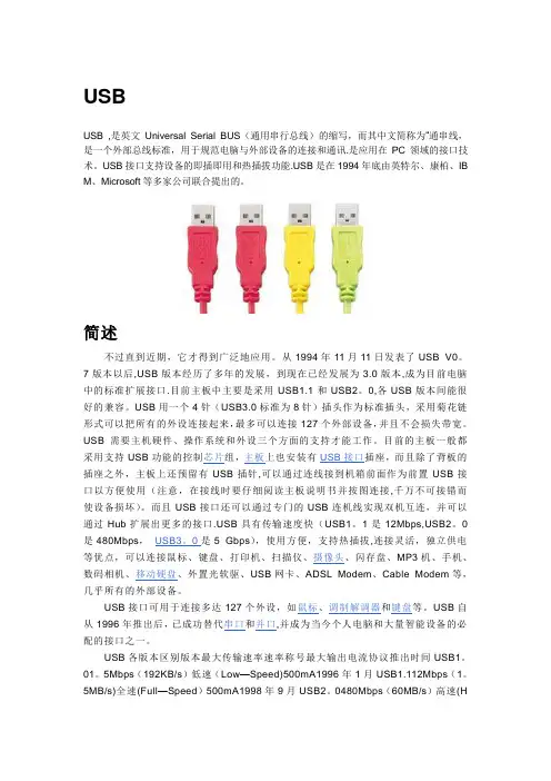
USBUSB ,是英文Universal Serial BUS(通用串行总线)的缩写,而其中文简称为“通串线,是一个外部总线标准,用于规范电脑与外部设备的连接和通讯.是应用在PC领域的接口技术。
USB接口支持设备的即插即用和热插拔功能.USB是在1994年底由英特尔、康柏、IB M、Microsoft等多家公司联合提出的。
简述不过直到近期,它才得到广泛地应用。
从1994年11月11日发表了USB V0。
7版本以后,USB版本经历了多年的发展,到现在已经发展为3.0版本,成为目前电脑中的标准扩展接口.目前主板中主要是采用USB1.1和USB2。
0,各USB版本间能很好的兼容。
USB用一个4针(USB3.0标准为8针)插头作为标准插头,采用菊花链形式可以把所有的外设连接起来,最多可以连接127个外部设备,并且不会损失带宽。
USB需要主机硬件、操作系统和外设三个方面的支持才能工作。
目前的主板一般都采用支持USB功能的控制芯片组,主板上也安装有USB接口插座,而且除了背板的插座之外,主板上还预留有USB插针,可以通过连线接到机箱前面作为前置USB接口以方便使用(注意,在接线时要仔细阅读主板说明书并按图连接,千万不可接错而使设备损坏)。
而且USB接口还可以通过专门的USB连机线实现双机互连,并可以通过Hub扩展出更多的接口.USB具有传输速度快(USB1。
1是12Mbps,USB2。
0是480Mbps,USB3。
0是5 Gbps),使用方便,支持热插拔,连接灵活,独立供电等优点,可以连接鼠标、键盘、打印机、扫描仪、摄像头、闪存盘、MP3机、手机、数码相机、移动硬盘、外置光软驱、USB网卡、ADSL Modem、Cable Modem等,几乎所有的外部设备。
USB接口可用于连接多达127个外设,如鼠标、调制解调器和键盘等。
USB自从1996年推出后,已成功替代串口和并口,并成为当今个人电脑和大量智能设备的必配的接口之一。
type c口layout设计规则摘要:一、Type-C接口概述1.Type-C接口的定义和背景2.Type-C接口的优势和应用场景二、Type-C接口的布局设计规则1.插头尺寸和形状2.引脚定义和功能3.接口布局和排布规则4.电源和数据传输的兼容性5.耐压和防护设计三、Type-C接口在各个领域的应用1.电子设备中的应用2.汽车充电中的应用3.数据中心和网络设备中的应用4.其他行业领域的应用四、Type-C接口的发展趋势和展望B4和Thunderbolt 4等新标准的推出2.Type-C接口在物联网和5G领域的应用3.Type-C接口的普及和未来市场前景正文:一、Type-C接口概述Type-C接口,全称USB Type-C,是一种由USB Implementers Forum (USB-IF)组织制定的全新USB接口标准。
自2014年发布以来,Type-C接口凭借其小巧、易用、高速传输、双向充电等特点迅速成为消费电子设备的标配。
它解决了传统USB接口正反插不便、传输速度慢等问题,为用户带来了更便捷的体验。
二、Type-C接口的布局设计规则1.插头尺寸和形状Type-C接口的插头采用了全新的设计,具有更小的尺寸和更简洁的外观。
插头呈椭圆形,两侧对称,用户可以轻松地实现正反插。
2.引脚定义和功能Type-C接口共有24个引脚,其中包含了电源、数据、视频和其他功能引脚。
电源引脚支持最大100瓦的功率输出,数据引脚支持USB 3.1 Gen 2标准的最高10Gbps传输速度。
3.接口布局和排布规则Type-C接口的布局需要遵循一定的规则,如电源和数据引脚的位置、间距等。
这些规则旨在确保设备的兼容性和稳定性。
4.电源和数据传输的兼容性Type-C接口支持多种电源和数据传输标准,如USB-PD、USB 3.1、HDMI、DisplayPort等。
这使得Type-C接口能够适应各种设备的需要,提高设备的通用性和灵活性。
Dell G3 Type-C接口协议1. 引言戴尔(Dell)是一家全球知名的计算机科技公司,致力于为用户提供高性能的电脑和配件。
戴尔的G3系列是一款专为游戏爱好者设计的笔记本电脑系列。
其中,G3 Type-C接口协议是指该系列笔记本电脑上的Type-C接口使用规范和协议。
本文将详细介绍戴尔G3 Type-C接口协议的相关内容,包括接口功能、技术规范、连接方式、兼容性和应用场景等方面。
2. 接口功能G3 Type-C接口是一种全新的USB接口标准,具有多种功能和特点。
主要功能如下:2.1 数据传输G3 Type-C接口支持高速数据传输,最高可达到10Gbps的传输速度。
这意味着用户可以通过该接口快速传输大量数据,如文件、图片、音频和视频等。
2.2 电源传输G3 Type-C接口支持高功率电源传输,最高可达到100W的功率输出。
这意味着用户可以通过该接口为设备充电,如笔记本电脑、智能手机和平板电脑等。
2.3 视频输出G3 Type-C接口支持视频输出功能,可以将视频信号传输到外部显示器或投影仪上。
用户可以通过该接口连接外部显示设备,实现高清视频播放和多屏幕扩展等功能。
2.4 音频输出G3 Type-C接口支持音频输出功能,可以将音频信号传输到外部音响或耳机上。
用户可以通过该接口连接外部音频设备,享受更好的音频体验。
3. 技术规范G3 Type-C接口的技术规范主要包括物理接口、电气接口和协议规范等方面。
3.1 物理接口G3 Type-C接口采用了一种新型的物理接口设计,具有较小的尺寸和可逆插拔特点。
这意味着用户可以不用担心接口插反的问题,插拔更加方便快捷。
3.2 电气接口G3 Type-C接口采用了新的电气接口标准,支持高速数据传输和高功率电源传输。
同时,该接口还具有较低的功耗和较高的数据传输稳定性。
3.3 协议规范G3 Type-C接口的协议规范主要包括USB 3.1和USB PD(Power Delivery)等标准。
![USB3.1 Type C 认证规范 USB-Port Controller Specification R1.0 [21051020] (1)](https://uimg.taocdn.com/e2948cd2d5bbfd0a79567366.webp)
Universal Serial Bus Type-C TM Port Controller Interface SpecificationRevision 1.0October 20, 2015Copyright © 2015, USB 3.0 Promoter Group:Hewlett-Packard Company, Intel Corporation, Microsoft Corporation, Renesas, STMicroelectronics, and Texas InstrumentsAll rights reserved.LIMITED COPYRIGHT LICENSE: The USB 3.0 Promoters grant a conditional copyright license under the copyrights embodied in the USB Type-C Cable and Connector Specification to use and reproduce the Specification for the sole purpose of, and solely to the extent necessary for, evaluating whether to implement the Specification in products that would comply with the specification. Without limiting the foregoing, use of the Specification for the purpose of filing or modifying any patent application to target the Specification or USB compliant products is not authorized. Except for this express copyright license, no other rights or licenses are granted, including without limitation any patent licenses. In order to obtain any additional intellectual property licenses or licensing commitments associated with the Specification a party must execute the USB 3.0 Adopters Agreement. NOTE: By using the Specification, you accept these license terms on your own behalf and, in the case where you are doing this as an employee, on behalf of your employer.INTELLECTUAL PROPERTY DISCLAIMERTHIS SPECIFICATION IS PROVIDED TO YOU “AS IS” WITH NO WARRANTIES WHATSOEVER, INCLUDING ANY WARRANTY OF MERCHANTABILITY, NON-INFRINGEMENT, OR FITNESS FOR ANY PARTICULAR PURPOSE. THE AUTHORS OF THIS SPECIFICATION DISCLAIM ALL LIABILITY, INCLUDING LIABILITY FOR INFRINGEMENT OF ANY PROPRIETARY RIGHTS, RELATING TO USE OR IMPLEMENTATION OF INFORMATION IN THIS SPECIFICATION. THE PROVISION OF THIS SPECIFICATION TO YOU DOES NOT PROVIDE YOU WITH ANY LICENSE, EXPRESS OR IMPLIED, BY ESTOPPEL OR OTHERWISE, TO ANY INTELLECTUAL PROPERTY RIGHTS.All implementation examples and reference designs contained within this Specification are included as part of the limited patent license for those companies that execute the USB 3.0 Adopters Agreement.All product names are trademarks, registered trademarks, or service marks of their respective owners.CONTENTSSpecification Work Group Chairs / Specification Editors (7)Specification Work Group Contributors (7)Revision History (9)1Introduction (10)1.1Purpose (10)1.2Scope (10)1.3Related Documents (11)1.4Conventions (11)1.4.1Precedence (11)1.4.2Keywords (11)1.4.3Numbering (12)1.5Terms and Abbreviations (12)2Overview (13)2.1Introduction (13)2.2USB Type-C Port Controller (TCPC) Interface (13)3Type-C Port Controller Requirements (14)3.1Port Power Control for VBUS and VCONN (14)3.2USB CC Logic (14)3.3USB-PD Message Delivery (14)3.4Debug Accessory Detection (15)3.5TCPC State-Machines (16)3.6USB Type-C Port Controller Requirements for Source, Sink, and DRP (18)3.6.1Source Requirements (18)3.6.2Sink Requirements: (19)3.6.3Sink with Accessory Support (20)3.6.4DRP Requirements (21)4USB Type-C Port Controller Interface (22)4.1Register Map (23)4.2TCPC SMBus Optional Normative Requirements (25)4.3Writing and Reading TCPC Registers (25)4.3.1Writing Single Byte Registers (25)4.3.2Reading Single Byte Registers (26)4.3.3Writing Multiple-Byte Registers (26)4.3.4Reading Multiple-Byte Registers (27)4.3.5Writing the TRANSMIT_BUFFER (27)4.3.6Reading the RECEIVE_BUFFER (28)4.4Register Definition (29)4.4.1Identification Registers (29)4.4.2ALERT Register (Required) (31)4.4.3Mask Registers (33)4.4.4CONFIGURE STANDARD OUTPUT (Optional Normative) (36)4.4.5Control and Configuration Registers (37)4.4.6Status Registers (43)4.4.7COMMAND (Required) (49)4.4.8Capability Registers (52)4.4.9MESSAGE_HEADER_INFO (Required) (56)4.4.10RECEIVE_DETECT (Required) (56)4.4.11RECEIVE_BUFFER (Required) (57)4.4.12TRANSMIT (Required) (59)4.4.13TRANSMIT_BUFFER (Required) (60)4.4.14VBUS_VOLTAGE (Optional Normative) (61)4.4.15Voltage Thresholds (62)4.4.16VENDOR_DEFINED Registers (64)4.5STANDARD IO SIGNALS (65)4.5.1STANDARD INPUT SIGNALS (Optional Normative) (65)4.5.2STANDARD OUTPUT SIGNALS (Optional Normative exceptAlert#) (65)4.6TCPC Connection State Machine and Flows (67)4.7PD Communication Operational Model (73)4.7.1Transmitting an SOP* Message (73)4.7.2Transmitting a Hard Reset Message (73)4.7.3Receiving an SOP* message (73)4.7.4Receiving a Hard Reset message (74)4.8Power Management (75)4.8.1I2C Interface (75)4.8.2PD Messaging (75)4.8.3CC Status Reporting (75)4.8.4V BUS Reporting (76)4.8.5Fault Status Reporting (76)4.9TCPC Timing Constraints (78)4.10I2C Physical Interface Specifications (78)A Informative TCPM State-Machine Diagrams (81)FIGURESFigure 1-1. USB Type-C Port Manager to USB Type-C Port Controller Interface (10)Figure 2-1. TCPC Interface (13)Figure 3-1. Rx State-Machine Implemented in TCPC (16)Figure 3-2. Tx State-Machine Implemented in TCPC (17)Figure 3-3. Hard Reset Transmission State-Machine implemented in the TCPC (17)Figure 4-1. Writing Consecutive Registers with or without the SMBUS Protocol (25)Figure 4-2. Reading Consecutive Registers with or without the SMBus Protocol (26)Figure 4-3. Writing a 2-Byte Register with or without the SMBus Protocol (26)Figure 4-4. Reading a 2-Byte Register with or without the SMBus Protocol (27)Figure 4-5. Writing the TRANSMIT_BUFFER with or without the SMBus Protocol (27)Figure 4-6. Reading the RECEIVE_BUFFER with or without the SMBus Protocol (28)Figure 4-7. Automatic V BUS Sink Discharge by the TCPC after a Disconnect (43)Figure 4-8. Transition from vSafe5V to High Voltage (51)Figure 4-9. Transition from High Voltage to vSafe5V (51)Figure 4-10. TCPC Power-On State Machine (67)Figure 4-11. TCPC State Machine before a Connection (68)Figure 4-12. TCPC State Machine After a Connection (69)Figure 4-13. TCPC State Machine Debug Accessory (69)Figure 4-14. DRP Initialization and Connection Detection (70)Figure 4-15. Source Disconnect (71)Figure 4-16. Sink Disconnect (72)Figure A-1. Rx State Machine Implemented in TCPM (81)Figure A-2. Tx State Machine Implemented in TCPM (81)Figure A-3. Hard Reset State Machine Implemented in TCPM (82)TABLESTable 4-1. Register Map (23)Table 4-2. VENDOR_ID Register Definition (29)Table 4-3. PRODUCT_ID Register Definition (29)Table 4-4. DEVICE_ID Register Definition (29)Table 4-5. USBTYPEC_REV Register Definition (Required) (29)Table 4-6. USBPD_REV_VER Register Description (30)Table 4-7. PD_INTERFACE_REV Register Description (30)Table 4-8. ALERT Register Definition (31)Table 4-9. ALERT_MASK Register Definition (33)Table 4-10. POWER_STATUS_MASK Register Definition (34)Table 4-11. FAULT_STATUS_MASK Register Definition (35)Table 4-12. CONFIG_STANDARD_OUTPUT Register Definition (36)Table 4-13. TCPC_Control Register Definition (37)Table 4-14. ROLE_CONTROL Register Definition (38)Table 4-15. Power on Default Conditions (39)Table 4-16. FAULT_CONTROL Register Definition (39)Table 4-17. POWER_CONTROL Register Definition (40)Table 4-18. Discharge Timing Parameters (41)Table 4-19. Debounce requirements (44)Table 4-20. CC_STATUS Register Definition (44)Table 4-21. POWER_STATUS Register Definition (46)Table 4-22. FAULT_STATUS Register Definition (47)Table 4-23. COMMAND Register Definition (50)Table 4-24. DEVICE_CAPABILITIES_1 Register Definition (52)Table 4-25. DEVICE_CAPABILITIES_2 Register Definition (53)Table 4-26. STANDARD_INPUT_CAPABILITIES Register Definition (54)Table 4-27. STANDARD_OUTPUT_CAPABILITIES Register Definition (54)Table 4-28. MESSAGE_HEADER_INFO Register Definition (56)Table 4-29. RECEIVE_DETECT Register Definition (56)Table 4-30. RECEIVE_BYTE_COUNT Definition (57)Table 4-31. RX_BUF_FRAME_TYPE Definition (57)Table 4-32. RX_BUF_HEADER Definition (58)Table 4-33. RX_BUFFER_DATA_OBJECTS Definition (58)Table 4-34. TRANSMIT Register Definition (59)Table 4-35. TRANSMIT_BYTE_COUNT Definition (60)Table 4-36. TX_BUF_HEADER Definition (60)Table 4-37. TX_BUFFER_DATA_OBJECTS Definition (60)Table 4-38. VBUS_VOLTAGE Register Definition (61)Table 4-39. VBUS_SINK_DISCONNECT_THRESHOLD Register Description (62)Table 4-40. VBUS_STOP_DISCHARGE_THRESHOLD Register Description (62)Table 4-41. VBUS_VOLTAGE_ALARM_HI_CFG Register Description (63)Table 4-42. VBUS_VOLTAGE_ALARM_LO_CFG Register Description (63)Table 4-43. Standard Input Signals (65)Table 4-44. Standard Output Signals (65)Table 4-45. TCPC Timing Constraints (78)Table 4-46. I2C Static Characteristics (79)Table 4-47. I2C Dynamic Characteristics (79)Specification Work Group Chairs / Specification EditorsIntel Corporation (USB 3.0 Promoter company) Christine Krause – Subgroup WG co-chair, Specification Co-author Chee Lim Nge – Subgroup WG co-chair, Specification Co-authorSpecification Work Group ContributorsAdvanced Micro Devices Will HarrisJason Hawken Joseph ScanlonPeter TengKen XueAnalogix Semiconductor,Inc.Greg StewartApple Sree AnantharamanWilliam FerryArulchandran Paramasivam Reese SchreiberDavid SekowskiSascha TietzHsiao-Ping Jennifer TsaiCadence Design Systems, Inc. Jacek DudaPawel EichlerWojciech Kloska Michal StaworkoCanova Tech Matteo Casalin Davide Ghedin Nicola ScantamburloCypress Semiconductor Anup NayakJagadeesan Raj Subu Sankaran Ganesh SubramaniamDell Inc. Mohammed hijaziMarcin Nowak Siddhartha Reddy Merle WoodDisplayLink (UK) Ltd. Pete BurgersDan Ellis Kevin JacobsRichard PetrieJason YoungEllisys Mario Pasquali Chuck TreftsEtron Technology, Inc. Shihmin Hsu Chien-Cheng KuoFairchild Semiconductor Oscar Freitas Christian Klein Erik Maier Fresco Logic Inc. Tim Barilovits Bob McVay Jeffrey YangGoogle Inc. Alec BergJim GuerinMark Hayter Sameer NandaVincent PalatinDavid SchneiderScott CollyerGranite River Labs Mike EngbretsonHewlett Packard Roger Benson Robin CastellIntel Corporation Bob DunstanAbdul IsmailSanjeev Jahagirdar Vijaykumar KadgiHenrik LeegaardTim McKeeBrad SaundersKarthi VadiveluKeysight Technologies Inc. Jit LimLattice SemiconductorCorpYoung Il Kim Thomas WatzkaMCCI Corporation Terry Moore Sherri Russo Chris YokumMicrochip Technology Inc. Josh AverytMark BohmShannon Cash Brian MarleySantosh shetttyJohn SistoRichard WahlerNeil WinchesterMicrosoft Corporation Randy AullAnthony ChenVivek GuptaDavid Hargrove Robbie HarrisTeemu HeleniusKai InhaJayson KastensIsmo ManninenRahul RamadasNathan ShermanTatu TomppoMQP Electronics Ltd. Sten Carlsen Pat CroweNXP Semiconductors Ken JaramilloAbhijeet Kulkarni Vijendra KuroodiKrishnan TNBart VertentenON Semiconductor Bryan McCoyParade Technologies, Inc. Jian ChenCraig Wiley Paul Xu Alan YuenQualcomm, Inc Craig Aiken Shadi HawawiniRealtek Semiconductor Corp. Charlie HsuRay LeeRyan LinTerry LinChanghung WuRenesas Electronics Corp. Kiichi Muto Hajime NozakiRichtek Technology Corporation Kenny ChanHM ChangPatrick ChangeBryan HuangSpice HuangChunan KuoTony LaiHeinz WeiScott WuAlex YangMing-Shih YuRicoh Company Ltd. Yasuyuki HayashiTatsuya Irisawa Satoshi Oie Yuuji TsutsuiROHM Co., Ltd. Kris BaharRuben Balbuena Nobutaka ItakuraYoshinori OhwakiTakashi SatoSTMicroelectronics Jérôme BachNathalie BallotChristophe lorin Meriem MerselFederico MusarraRichard O'ConnorLegrand PascalSynopsys, Inc. Zongyao WenTexas Instruments Felipe Balbi Scott Jackson Deric Waters VIA Technologies, Inc. Jay Tseng Fong-Jim WangRevision HistoryOctober 20, 2015Interface Specification1 IntroductionWith the continued success of USB Power Delivery, there exists a need to define a commoninterface from a USB Type-C TM Port Manager to a Simple USB Type-C Port Controller. This specification defines this interface.Figure 1-1 shows the interconnection between the USB Type-C Port Manager, TCPM, and three USB Type-C Port Controllers, TCPCs. One TCPM may be used to drive multiple TCPCs subjectbetween theFigure 1-1. USB Type-C Port Manager to USB Type-C Port Controller Interface1.1 PurposeThe USB Type-C Port Controller Interface, TCPCI, is the interface between a USB Type-C Port Manager and a USB Type-C Port Controller. This specification standardizes the communication between the USB Type-C Port Manager (TCPM) and the USB Type-C Port Controller (TCPC) while meeting the USB Type-C Power Delivery requirements.The goal of the USB Type-C Port Controller Interface (TCPCI) is to provide a defined interface between a TCPC and a TCPM in order to standardize and simplify USB Type-C Port Manager implementations.The TCPC is a functional block which encapsulates V BUS and V CONN power controls, USB Type-C CC logic, and the USB PD BMC physical layer and protocol layer other than the message creation.1.2 ScopeThis specification is intended as a supplement to USB 3.1, USB Type-C , and USB PDspecifications. It addresses only the elements required to implement and support the USB Type-C Port Controller.Normative information is provided to allow interoperability of components designed to this specification. Informative information, when provided, may illustrate possible design implementations.Platform Policy ManagerOS Policy ManagerPPM InterfacePD System Policy Manager(optional)PD Device Policy Manager(for PD-capable ports)1.3Related DocumentsUSB 3.1 Universal Serial Bus Revision 3.1 SpecificationThis includes the entire document release package./developers/docsUSB PD USB Power Delivery Specification, Revision 2.0, August 11, 2014 /developers/docsUSB Type-C USB Type-C Connector Specification, Revision 1.0, August 11, 2014 /developers/docs1.4Conventions1.4.1PrecedenceIf there is a conflict between text, figures, and tables, the precedence shall be tables, figures, and then text.1.4.2KeywordsThe following keywords differentiate between the levels of requirements and options.1.4.2.1InformativeInformative is a keyword that describes information within this specification that intends to discuss and clarify requirements and features as opposed to mandating them.1.4.2.2MayMay is a keyword that indicates a choice with no implied preference.1.4.2.3N/AN/A is a keyword that indicates a field or value is not applicable and has no defined value and shall not be checked or used by the recipient.1.4.2.4NormativeNormative is a keyword that describes features mandated by this specification.1.4.2.5OptionalOptional is a keyword that describes features not mandated by this specification. However, if an optional feature is implemented, the feature shall be implemented as defined by this specification (optional normative).1.4.2.6ReservedReserved is a keyword indicating reserved bits, bytes, words, fields, and code values that are set-aside for future standardization. Their use and interpretation may be specified by future extensions to this specification and, unless otherwise stated, shall not be utilized or adapted by vendor implementation. A reserved bit, byte, word, or field shall be set to zero by the sender and shall be ignored by the receiver. Reserved field values shall not be sent by the sender, and if received, shall be ignored by the receiver.1.4.2.7ShallShall is a keyword indicating a mandatory (normative) requirement. Designers are mandated to implement all such requirements to ensure interoperability with other compliant Devices.1.4.2.8ShouldShould is a keyword indicating flexibility of choice with a preferred alternative equivalent to the phrase “it is recommended that”.1.4.3NumberingNumbers immediately followed by a lowercase “b” (e.g., 01b) are binary values. Numbers immediately followed by an uppercase “B” are byte values. Numbers immediately followed by a lowercase “h” (e.g., 3Ah) are hexadecimal values. Numbers not immediately followed by either a “b”, “B”, or “h” are decimal values.1.5Terms and Abbreviations2Overview2.1Introduction2.2USB Type-C Port Controller (TCPC) InterfaceFigure 2-1. TCPC InterfaceThe USB Type-C Port Controller Interface, TCPCI, is the interface between a USB Type-C Port Manager and a USB Type-C Port Controller. The goal of the USB Type-C Port Controller Interface (TCPCI) is to provide a defined interface between a TCPC and a TCPM in order to standardize and simplify USB Type-C Port Manager implementations.The TCPC is a functional block which encapsulates V BUS and V CONN power controls, USB Type-C CC logic, and the USB PD BMC physical layer and protocol layer other than the message creation. The TCPC shall NOT include support for USB PD BFSK.3Type-C Port Controller RequirementsThis chapter describes the requirements of a USB Type-C Port Controller. The TCPC has three functions:∙USB Type-C Port Power Control for V BUS and V CONN (required)∙USB Type-C CC Control and sensing (required)∙USB PD Message delivery (required)∙Standard Inputs and Outputs are defined for simplified external interfacing (optional)The TCPC uses I2C to communicate with the TCPM. The TCPC is an I2C slave with Alert# signal for requesting attention.3.1Port Power Control for VBUS and VCONNA Source capable TCPC shall provide a register which allows the TCPM to control V BUS Sourcing. A Sink capable TCPC shall provide a register which allows the TCPM to ControlV BUS Sinking.To ensure safety in case the I2C interface fails, the TCPC that is sourcing V BUS higher than 5V shall autonomously stop sourcing V BUS if the Sink is detached.The TCPC shall implement a force discharge circuit. A low current bleed discharge may also be implemented. The force discharge is a larger current discharge used to discharge to below vSafe0V upon detecting a Disconnect per USB Type-C (exiting the Attached.SRC state). The discharge shall be available for both Source and Sink.A TCPC shall include monitoring for the presence of V BUS (VSafe5V, VSafe0V). The TCPC shall implement high and low voltage alarms if it Sinks or Sources voltage greater tha n VSafe5V.A Source or DRP TCPC shall include control for V CONN sourcing. A Sink TCPC shall include control for V CONN sourcing if V CONN Swap or Sink w/Accessory is supported. V CONN sourcing shall meet the tV CONN ON and tV CONN OFF timing requirement per USB Type-C.A TCPC shall implement low power states as defined in this specification.3.2USB CC LogicThe TCPC shall implement logic for controlling the CC pins on the USB Type-C Connector. The TCPC shall implement a method to control the Port Power Role and to report the state of the CC lines, Rp/Rd control, and CC sense/debounce/interrupt.3.3USB-PD Message DeliveryThe TCPC shall implement BMC encoding. The TCPC shall NOT include support for USB PD BFSK. The TCPC shall implement the portion of the Protocol layer in the USB PD specification as shown in Figure 3-2, and 3-3. The TCPC is opaque from a USB PD point of view. The TCPC sends and receives messages constructed in the TCPM and places them on the CC connections. The TCPC does not interpret the USB PD messages.The TCPC shall implement the entire USB PD PHY layer with BMC encoding. The TCPC shall implement a portion of the Transmit state machine.∙CRCReceiveTimer (PRL_Tx_wait_for_Phy_Response_state)∙RetryCounter (PRL_Tx_Check_RetryCounter State)∙MessageID is not checked in the TCPC when a non-GoodCRC message is received.Retried messages that are received are passed to the TCPM via I2C ∙Received GoodCRC must match the transmitted MessageID and SOP type before it is considered valid∙Two things allow the TCPM to track the MessageID even when asynchronous messages are receivedo If ALERT.ReceiveSOP*MessageStatus is not cleared when the TCPM requestsa TRANSMIT then the I2C command is NAK’d orTransmitSOP*MessageDiscarded bit in the ALERT register is asserted.o If a message is received before the TCPC has processed a transmit request, it asserts the TransmitSOP*MessageDiscarded bit in the ALERT register.∙BIST handling shall be as follows: Each incoming BIST message may be passed up to the policy engine as is any other incoming USB PD Message, or responded to with a GoodCRC without passing to the policy engine. The TCPC shall provide a mechanism to allow the policy engine to send a BIST Continuous Carrier Mode 2 message fortBistContMode.3.4Debug Accessory DetectionThe TCPC may implement autonomous detection of the Debug Accessory State (vRd/vRd) per USB Type-C. This allows the TCPC to indicate a vRd/vRd connection without TCPM involvement, and indicates this via the DebugAccessoryConnected# output andPOWER_STATUS.DebugAccessoryConnected. The TCPC performs autonomous detection of the Debug Accessory state if TCPC_CONTROL.DebugAccessoryControl=0b.The TCPM may control entry to the Debug Accessory Detected state by settingTCPC_CONTROL.DebugAccessoryControl=1b.The behavior in the Debug Accessory state is defined in USB Type-C in Appendix B.3.5 TCPC State-MachinesThis section describes the normative State-Machines for the TCPC. The informative TCPM State-Machines can be found in Appendix A.Figure 3-1. Rx State-Machine Implemented in TCPC1becomes idle again (see USB-PD specification). Two alternate allowable transitions are shown.2Messages do not include Hard Reset or Cable Reset signals or expected GoodCRC messages (GoodCRC messages are only expected after the TCPC PHY has received the tx message and the TCPC Tx state-machine is in the PRL_Tx_Wait_for_PHY_response state).3The TCPC may not discard the transmission if the received message is a Ping message.1The CRCReceiveTimer is only started after the PHY has sent the message. If the message is not sent due to a busy channel then the CRCReceiveTimer will not be started (see USB-PD Rev2.0 v1.1 Section 6.5.1).2This indication is sent by the PHY Layer when a message has been discarded due to V BUS or CC being busy, and after V BUS or CC becomes idle again (see USB-PD REv2.0 v1.1 Section 5.8). The CRCReceiveTimer is not running in this case since no message has been sent.Figure 3-2. Tx State-Machine Implemented in TCPCFigure 3-3. Hard Reset Transmission State-Machine implemented in the TCPC3.6USB Type-C Port Controller Requirements for Source, Sink, and DRP3.6.1Source RequirementsA TCPC, which supports Source port operation, is defined as follow:1. A Source TCPC shall provide control of V BUS source path (see Table 4-23. COMMANDRegister Definition).2. A Source TCPC may provide over voltage protection and over current protectioncircuitry for the V BUS source path (see FAULT_STATUS.OCP/OVP andFAULT_CONTROL.OCP/OVP).3. A Source TCPC shall provide control of a V CONN switch (seePOWER_CONTROL.V CONN PowerSupported and POWER_CONTROL.EnableVconn).4. A Source TCPC may include monitoring for the presence of V CONN (seePOWER_STATUS.V CONN Present).3.6.2Sink Requirements:A TCPC, which supports Sink port operation, is defined as follow:1. A Sink TCPC shall contain CC logic that implements a mechanism to present Rd in adead battery condition (see Table 4-15. Power on Default Conditions).2. A Sink TCPC may include the monitoring of the presence of V CONN (seePOWER_CONTROL.V CONN PowerSupported and POWER_STATUS.V CONN Present).3. A Sink TCPC shall provide control of V BUS sink path (see COMMAND).4. A Sink TCPC shall provide a mechanism for detecting a Disconnect if it is capable ofsinking a voltage greater than vSafe5V (see Section 4.4.15.1).5. A Sink TCPC shall provide a mechanism for detecting vSafe0V.3.6.3Sink with Accessory SupportA TCPC, which supports Sink with Accessory Support operation, is defined as follow:1. A Sink TCPC shall contain CC logic that implements a mechanism to present Rd in adead battery condition (see Table 4-15. Power on Default Conditions).2. A Sink TCPC shall provide control of V CONN source path (seePOWER_CONTROL.V CONN PowerSupported and POWER_CONTROL.EnableV CONN).3. A Sink TCPC may include the monitoring of the presence of V CONN (seePOWER_STATUS.V CONN Present).4. A Sink TCPC shall provide control of V BUS sink path (see COMMAND).5. A Sink TCPC shall provide a mechanism for detecting a Disconnect if it is capable ofsinking a voltage greater than vSafe5V (see Section 4.4.15.1).6. A Sink TCPC shall provide a mechanism for detecting vSafe0V.Sink with Accessory support is optional, but if implemented shall follow the table below.3.6.4DRP RequirementsA TCPC, which supports Dual Role Port operation, is defined as follow:1. A Dual Role TCPC shall contain CC logic to detect the insertion of a Source, Sink, andAudio and debug accessory (see ROLE_CONTROL).2. A Dual Role TCPC shall contain CC logic that implements a mechanism to present Rdin a dead battery condition (see CC_STATUS).3. A Dual Role TCPC shall provide control of V BUS source path (see COMMAND).4. A Dual Role TCPC shall provide control for a Vconn switch (seePOWER_CONTROL.V CONN PowerSupported and POWER_CONTROL.EnableV CONN)5.The TCPC shall include the monitoring of the presence of V CONN (seePOWER_STATUS.V CONN Present).6. A DRP TCPC shall provide a mechanism for detecting a Disconnect if it is capable ofsinking a voltage greater the vSafe5V (see Section 4.4.15.1).7. A DRP TCPC shall provide a mechanism for detecting vSafe0V.4USB Type-C Port Controller InterfaceThe USB Type-C Port Controller Interface (TCPCI) is a low level interface which handles V BUS and V CONN power connections, CC communication and USB-PD message delivery through a simple register interface. Communication between the TCPC and the USB Type-C Port Manager (TCPM) is over an I2C bus.The TCPCI uses the I2C protocol with the following behaviors:1.The TCPM is the only master on the I2C bus.2.The TCPC is a slave device on the I2C bus.3.The TCPM designer must meet the I2C bus loading requirements when determiningthe maximum number of devices on the I2C bus.4.Each USB Type-C port has its own unique I2C slave address. The TCPC may supportmultiple USB Type-C ports. In case the TCPC supports multiple ports, each USB Type-C port shall have a unique I2C slave address.5.The TCPC shall support Fast-mode (Fm+) bus speed. It may also support other busspeeds.6.The TCPC shall have an open drain output, active low Alert# Pin. This pin is used toindicate a change of state, where Alert# pin is asserted when any Alert Bits are set.7.The TCPCI shall support an I/O voltage range from 1.8V to 3.6V.8.The TCPC as a slave device shall be accessible through I2C communication protocolscompliant with “I2C-bus specification and user manual Rev.6” (4th April 2014)/documents/user_manual/UM10204.pdf9.The TCPC should auto-increment the I2C internal register address of the last bytetransferred during a read independent of an ACK/NAK from the master.10.The TCPC may implement the SMBus version 3 bus protocol (Section 6.5 of theSMBus Specification, version 3.0 available at /specs/).11.The TCPC shall allow reads to every register even when defined as Write only. TheTCPM should assume the register information returned from a Write only register is not valid.12.The TCPC shall not NAK if the TCPM writes to a register or bit that is notimplemented or reserved.。
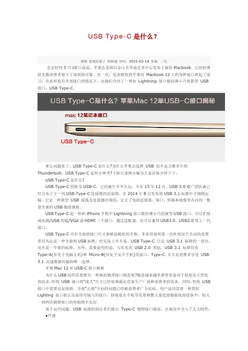
USB Type-C是什么?感谢把我给崩了的投递时间:2015-03-14 来源:三联北京时间3月10日凌晨,苹果在美国旧金山芳草地艺术中心发布了新款Macbook,它的轻薄给无数消费者留下了深刻的印象。
再一次,追求极致的苹果对 Macbook 12上的各种接口挥起了屠刀,在砍掉原有全部接口的情况下,向我们介绍了一种如 Lightning 接口般轻薄小巧的新型 USB 接口:USB Type-C。
那么问题来了,USB Type-C是什么?为什么苹果会选择 USB 而不是力推多年的Thunderbolt,USB Type-C是何方神圣?下面百事网小编为大家详细介绍下下。
USB Type-C是什么?USB Type-C简称为USB-C,它的诞生并不久远,早在13年12月,USB 3.0推广团队就已经公布了下一代USB Type-C连接器的渲染图,在2014年8月发布的USB 3.1标准中才刚刚定稿。
它是一种新型 USB 线缆及连接器的规范,定义了包括连接器、端口、容器和线缆等在内的一整套全新的USB物理规格。
USB Type-C是一种和iPhone手机中Lightning接口般轻薄小巧的新型USB接口,可以扩展成电源/USB传输/VGA或HDMI三个接口,通过适配器,还可以兼容USB3.0、USB2.0等上一代接口。
USB Type-C具有全新的接口尺寸和略显酷炫的名称,非常容易使第一次听到这个名词的消费者以为这是一种全新的USB标准,但实际上并不是。
USB Type-C 只是 USB 3.1 标准的一部分,而不是一个新的标准。
另外,需要说明的是,与常见的 USB 2.0 类似,USB 3.1 标准仍有Type-A(常见于电脑主机)和 Micro-B(常见于安卓手机)等接口,Type-C 并不是消费者享受 USB 3.1 高速数据传输的唯一选择。
苹果Mac 12单USB-C接口揭秘为什么USB组织需要推出一种新的物理接口规范呢?随着越来越多新型设备对于轻量化小型化的追求,传统 USB 接口的“庞大”尺寸已经很难满足设备生产厂商和消费者的需求。

三阶文件USB Type-C数据线设计规范页数1/19文件编号WI-EG-024 版本A/0修订履历版本修订内容日期修/制订者审核批准A/0 新制订2015-10-21i三阶文件USB Type-C数据线设计规范页数2/19文件编号WI-EG-024 版本A/01.0适用范围:本设计规范适用于鹏毅公司Type-C数据线规格书,未尽规格描述以USB3.1协会规范为准。
2.0编写依据:序号No. 文件编号Doc No. 文件名称 Doc Title1 GJB1217 电连接器试验方法2 MIL-STD-202G Test method standard electronic and electrical component parts3 GB/T 3048 电线电缆电性能试验方法4 GB4098 射频电缆试验方法5 EIA-364-101 Attenuation Test Procedure for Electrical Connectors, Sockets, Cable Assemblies or Interconnection Systems6 EIA-364-106 Standing Wave Ratio (SWR) Test Procedure for Electrical Connectors7 EIA-364-108 Impedance, Reflection Coefficient, Return Loss, and VSWR Measured in the Time and Frequency Domain Test Procedure for Electrical Connectors, CableAssemblies or Interconnection Systems8 GB5441.2 工作电容试验-电桥法9 EIA-364-103 Propagation Delay Test Procedure for Electrical Connectors, Sockets, Cable Assemblies or Interconnection Systems10 IEC 68-2-1 基本环境试验规程试验A:寒冷11 GB/T 2423.1 电工电子产品基本环境试验规程试验A:低温试验方法12 IEC 68-2-2 基本环境试验规程试验A:干热13 GB/T 2423.2 电工电子产品基本环境试验规程试验B:高温试验方法14 IEC 68-2-10 电工电子产品环境试验第2部分:试验方法试验J和导则:长霉0020的15 GB/T 2423.16 电工电子产品环境试验第2部分:试验方法试验J和导则:长霉16 ASTM G 21 Standard Practice for Determining Resistance of Synthetic Polymeric Materials to Fungi17 IEC 61587-1 Mechanical structures for electronic equipment―Tests for IEC 60917 and IEC 60297―Part 1 Climatic mechanical tests and safety aspects forcabinets racks subracks and chassis18 GR 487 Generic Requirements for Electronic Equipment Cabinets19 IEC 68-2-30 基本环境试验规程试验Db及导则:交变湿热(12+12h循环)20 GB/T 2423.4 电工电子产品基本环境试验规程试验Db:交变湿热试验方法21 IEC 68-2-52 电工电子产品环境试验第2部分:试验试验Kb:盐雾,交变(氯化钠溶液)22 GB/T 2423.18 电工电子产品环境试验第2部分:试验试验Kb:盐雾,交变(氯化钠溶液)23 IEC 529 Degrees of protection provided by enclosure(IP code)24 GB 4208 外壳防护等级(IP代码)三阶文件USB Type-C数据线设计规范页数3/19文件编号WI-EG-024 版本A/025 EIA-364-38B Cable pull-out test procedure for electrical connectors26 EIA-364-41C Cable flexing test procedure for electrical connectors27 IEC 60950 Safety of information technology equipment28 EN 60950 Safety of information technology equipment29 UL 60950 Safety of information technology equipment30 GB 4943 信息技术设备的安全31 IEC60332 Tests on electric cabies under fire conditions32 GB/T18380 电缆在火焰条件下的燃烧试验33 UL1581 Reference standard for electical wires,cables,and flexible cords34 GR 1217 Generic requirements for separable electrical connectors used in telecommunications hardware35 GR 950 Generic Requirements for Optical Network Unit (ONU) Closures 3.0 Type-C数据线正常工作和存储条件3.1Type-C数据线应能在下列条件下正常工作:3.1.1 环境工作温度:-20℃~+70℃(仅作单体验证目的,与整机匹配时以整机试验环境为准);3.1.2 相对湿度:5%~95%;3.1.3 大气压力:86 kPa~106kPa;3.1.4 Type-C数据线的存储温度:-40℃~+85℃;4.0 Type-C连接器的PIN点定义三阶文件USB Type-C 数据线设计规范页 数 4/19 文件编号 WI-EG-024版本A/04.1 Type-C 插头外形尺寸设计要求4.2 Type-C 系列产品的设计要求 4.2.1 Type-C 数据线产品种类:TYPE-C TO USB 2.0 AM TYPE-C TO TYPE-C (2.0版本) TYPE-C TO USB 3.0 AM TYPE-C TO MICRO USB TYPE-C TO TYPE-C (3.1版本)TYPE-C TO USB3.0 BM4.3 USB3.1 Type-C TO Type-C 接线定义铁壳宽度 8.25mm 铁壳厚度2.4mm铁壳外露长度 6.5mm 插头厚度 6.5mm Max 插头宽度12.5mm Max三阶文件USB Type-C数据线设计规范页数5/19文件编号WI-EG-024 版本A/04.4 USB2.0 Type-C TO Type-C接线定义三阶文件USB Type-C 数据线设计规范页 数 6/19 文件编号 WI-EG-024版本A/04.5 Type-C TO USB3.1 AM 接线定义三阶文件USB Type-C 数据线设计规范页 数 7/19 文件编号 WI-EG-024版本A/04.6 Type-C TO USB2.0 AM 接线定义4.7 Type-C TO USB3.1 BM 接线定义三阶文件USB Type-C 数据线设计规范页 数 8/19 文件编号 WI-EG-024版本A/04.8 Type-C TO USB2.0 Micro BM 接线定义三阶文件USB Type-C 数据线设计规范页 数 9/19 文件编号 WI-EG-024版本A/04.9 Type-C TO USB3.1 Micro BM 接线定义5.0 Type-C 系列线缆的设计要求:5.1 Type-C 标准线材线规要求三阶文件USB Type-C数据线设计规范页数10/19文件编号WI-EG-024 版本A/05.2 Type-C TO Legacy线材线规要求三阶文件USB Type-C数据线设计规范页数11/19文件编号WI-EG-024版本A/05.3 Type-C 标准线材的设计5.3.1同轴线设计5.3.2对绞线设计三阶文件USB Type-C数据线设计规范页数12/19文件编号WI-EG-024 版本A/06.0 Type-C系列数据线对eMARK的选用设计三阶文件USB Type-C数据线设计规范页数13/19文件编号WI-EG-024 版本A/07.0 Type-C系列数据线对上拉和下拉电阻的选用设计8.0 Type-C数据线外观要求如下:外观金属插头/pin脚检查1、参照样品和PDM图纸检验,线缆两端插头的结构外型(型号)要求与样品一致;2、插头不允许氧化/生锈、残缺、变形;3、用干布(无尘布)能擦除的脏污,允许;用干布(无尘布)不能擦除的脏污,不允许;【注:金属插头脏污不良超出1%(不良数/样本数)时,提交不合格电子流确认】4、插头上不允许有油渍;5、划痕L≤2mm,W≤0.1mm,用手触摸无深度感,允收一条;6、USB A公插头内不允许有溢胶的现象;7、USB A公插头内的连接器PIN脚不允许氧化/生锈、翘高、变形、PIN脚内陷/断裂不良;8、金属插头(USBA公以及MICRO B公)与注塑部分匹配正常,不允许歪斜,夹角90o±2.5o 色差检验整体数据线是否存在色差,色差问题须参照样品进行检验。
新版USBType-C新规范出炉继电器USB Type-C接口有可能成为未来多数笔记本电脑、智能手机的唯一数据接口,但这些仅支持USB接口的设备仍必须与那些非USB接口的设备进行交互,比如显示器、电视机等。
因此,设计人员需要考虑如何在单个连接器中实现USB和其他高速接口的转换,其中涉及到切换引脚功能、提供诸如ESD的外部瞬变保护以及维护信号质量等问题。
USB Type-C标准通过定义备用模式(Alt Mode)来满足这些需求,这种方法能够动态地更改引脚的功能,从而支持非USB的数据传输协议。
本文对各类标准进行了介绍,有了这些标准,USB Type-C才能连接到HDMI或其他非USB形式的数据接口。
本文中还包含将HDMI备用模式增加到USB Type-C接口时需要考虑的主要问题。
USB规范介绍HDMI Forum于2016年底发布了USB Type-C备用模式规范,此最新版USB标准共包括以下三个部分:USB Type-C接口规范USB Type-C接口规范在我们所熟知的Type-A和Type-B规范基础上进行了大幅度的修改。
对于普通用户来说,有两点改动需要注意:Type-C 接口尺寸为8.3mmx2.5mm,较之USB Type-A和Type-B小了很多,但却包含24个引脚,之前的版本只有4个引脚。
Type-C接口支持正反逆插,这是因为Type-C接口采用了对称结构,无论哪一面在上,所有的信号引脚都处在相同的相对位置上。
USB Type-C还可以通过D+/D-和VBUS/GND引脚与传统的USB 2.0系统进行交互。
其引脚布局还包括其他两个规范中定义的新功能引脚(包括备用模式)。
图1显示的是Type-C接口标准和备用模式引脚映射。
图1:显示备用模式映射的USB Type-C引脚布局USB Type 3.1规范USB Type 3.1规范更新了USB的电气性能,规定数据传输速率可达到10Gbps(规范中称为SuperSpeed+)。
USB3.1特有的TYPE-C数据线接口定义USB3.1特有的TYPE-C数据线接口定义TYPE-C数据线接口在之前USB3.1是啥这篇文章中,我们介绍了USB3.1与以往USB 版本速度上的区别。
今天重点介绍一下USB3.1特有的数据线接口USB TYPE-C接口。
USB Type-C接口,又称USB-C接口。
它是基于USB 3.1规范全新设计的连接器。
我们都知道苹果从在2012年发布iphone 5首次引入了Lightning数据线接口,其最大的特点是用户不再去区分手机数据线接口的正反面。
USB3.1的Type-C接口外观上最大特点也是数据线接口的上下端完全一致,用户也不必再去区分USB接口的正反面,如同苹果Lightning接口一样,两个方向都可以插入。
TYPE-C接口与Lightning接口的对比从上图中可以发现苹果数据线接口Lightning和USB Type-C数据线接口共同的特点是均不分正反面,Lightning接口我们可以认为它属于公头接口,Type-C接口属于母头接口。
通用性上Lightning接口只能用于苹果的产品,是苹果公司特有的数据线接口。
Type-C应用氛围更广,支持Type-C的数码产品均可使用。
Type-C数据线接口与其它USB接口的区别在以前关于USB2.0接口定义和USB3.0接口定义的文章中我们都介绍有USB的接口类型和USB封装,读者可详细了解。
这里重点介绍一下以往版本的中USB接口类型与Type-C接口的区别,从上图中可以发现USB2.0 接口规范中的Type-A、Type-B、mini-A、mini-B、Micro-A、Micro-B接口和USB3.0接口规范中的Type-B、Micro-B 接口都有一个共同的特点那就是防呆设计,而Type-C接口则不分正反面,USB3.1 Type-C的另一个大卖点就是对移动设备充电能力的的增强。
USB 3.1接口下的供电最高允许标准大幅提高到了20V/5A(仅限于Type-A/B),能够提供达100W的供电输出能力。
USBTYPEC拆解以及USB3.1规范详解USB全称为Universal Serial Bus,翻译为通用串行总线,是连接计算机系统与外部设备的一种串口总线标准,也是一种输入输出接口的技术规范,被广泛地应用于个人电脑和移动设备等信息通讯产品,并扩展至摄影器材、数字电视(机顶盒)、游戏机等其它相关领域。
随着IT行业不断进步,USB历经以下几个阶段:USB1.0:1.5Mbps(192KB/s)低速(Low-Speed)500mA,1996年1月;USB1.1:12Mbps(1.5MB/s)全速(Full-Speed)500mA,1998年9月;USB2.0:480Mbps(60MB/s)高速(High-Speed)500mA,2000年4月;USB3.0:5Gbps(640MB/s)超速(Super-Speed)900mA,2008年11月;USB3.1:10Gbps(1.25GB/s)超速加(SuperSpeed+)5A,2013年12月。
最新一代的USB 3.1 Gen2,传输速度为10Gbit/s,三段式电压5V/12V/20V,最大供电100W 。
而伴随USB3.1而来的C型USB接口:USB Type C大有一统消费电子接口的趋势,近期已占领各大品牌旗舰手机接口榜首。
一、USB Type C外观及引脚定义USB Type C接口以其纤薄、正反可插拔等诸多优势,得到了广泛运用,我们先看看USB Type C接头拆解图。
从上图拆解可见,USB Type C接口上下各有12个引脚,其引脚排列如下图:Type C母头引脚排列图Type C公头引脚排列图二、USB Type C三种工作模式USB3.1标准有三种工作模式:1:DRP。
主HOST/DEVICE可自由转换,类似电脑或MacBook。
USB Type C DRP工作模式示意图2:DFP。
下行端,主HOST端(上拉电阻)。
USB Type C DFP工作模式示意图3:UFP。
USB 3.1技术分析USB 3.1是最新的USB规范,该规范由英特尔等大公司发起。
数据传输速度提升可至速度10Gbps。
与USB 3.0技术相比,新USB技术使用一个更高效的数据编码系统,并提供一倍以上的有效数据吞吐率。
它完全向下兼容现有的USB 连接器与线缆。
USB3.1兼容现有的USB 3.0软件堆栈和设备协议、5Gbps的集线器与设备、USB 2.0产品。
SB是最普及的电子设备连接规范,但并非是唯一的连接规范。
最近数年,Thunderbolt等替代性规范也开始普及。
为了抵御其他连接规范的威胁,USB标准化组织USB开发者论坛(USB Implementers Forum)在大力推广被称作USB 3.1的新版USB规范,目标是弥补USB规范的一些短板。
USB 3.1是最新的USB规范,该规范由英特尔等大公司发起。
数据传输速度提升可至速度10Gbps。
与USB 3.0技术相比,新USB技术使用一个更高效的数据编码系统,并提供一倍以上的有效数据吞吐率。
它完全向下兼容现有的USB 连接器与线缆。
USB3.1兼容现有的USB 3.0软件堆栈和设备协议、5Gbps的集线器与设备、USB 2.0产品。
2008年11月12日USB 3.0推出之后,SuperSpeed带来了5Gbps高速传输效能,附加提供5V/0.9A电源。
随着传输速率的要求提高,加上也希望能提升供电能力,2013年1月6日USB IF协会(USB Implementers Forum)正式宣布要推出新的USB 3.0加强版(即USB 3.1)。
2013年7月31日宣布正式开始研发SuperSpeed 10Gbps,2013年12月3日USB 3.0 Promoter Group正式宣布USB 3.1诞生。
到了2014年6月份Computex Taipei 2014,ASMedia第一家正式展示原生USB 3.1晶片,实现SuperSpeed+,也就是SuperSpeed 10Gbps 速率。
4.1 Type-C插头外形尺寸设计要求铁壳宽度8.25mm铁壳厚度 2.4mm4.2Type-C系列产品的设计要求4.2.1 Type-C数据线产品种类:TYPE-C TO USB 2.0 AM TYPE-C TO TYPE-CTYPE-C TO USB 3.0 AM TYPE-C TO MICRO USBTYPE-C TO TYPE-C(3.1版本)TYPE-C TO USB3.0 BM5.0 Type-C 系列线缆的设计要求:三阶文件USB Type-C数据线设计规范页数12/20文件编号WI-EG-024 版本A/05.3.2对绞线设计6.0 Type-C系列数据线对eMARK的选用设计三阶文件USB Type-C数据线设计规范页数13/20文件编号WI-EG-024 版本A/0三阶文件USB Type-C数据线设计规范页数14/20文件编号WI-EG-024 版本A/07.0 Type-C系列数据线对上拉和下拉电阻的选用设计8.0 Type-C数据线外观要求如下:外观金属插头/pin脚检查1、参照样品和PDM图纸检验,线缆两端插头的结构外型(型号)要求与样品一致;2、插头不允许氧化/生锈、残缺、变形;3、用干布(无尘布)能擦除的脏污,允许;用干布(无尘布)不能擦除的脏污,不允许;【注:金属插头脏污不良超出1%(不良数/样本数)时,提交不合格电子流确认】4、插头上不允许有油渍;5、划痕L≤2mm,W≤0.1mm,用手触摸无深度感,允收一条;6、USB A公插头内不允许有溢胶的现象;7、USB A公插头内的连接器PIN脚不允许氧化/生锈、翘高、变形、PIN脚内陷/断裂不良;8、金属插头(USBA公以及MICRO B公)与注塑部分匹配正常,不允许歪斜,夹角90o±2.5o 色差检验整体数据线是否存在色差,色差问题须参照样品进行检验。
标签检查1、标签上的印刷图案和字体要求与样品一致,并清晰可辨;2、数据线上的标签不允许破损、折皱、起膜;3、插头上的铭牌在槽内偏移的最大尺寸不允许超过0.25mm;4、旗舰标签对折粘贴后的歪斜程度≤1mm;注塑部位1、注塑部位(USB A公外膜、DC插头外膜、磁环外膜)不允许缺胶、破损;。
USB A 3000次, 电气性能正常
Micro B 10000次, 电气性能正常Type-C 10000次电气性能正常
Micro USB插拔耐久测试前后:插入力大于等于6N,小于等于25N Type-C插拔耐久测试前后:插入力大于等于5N,小于等于20N
Micro USB插拔耐久测试前后:拔出力大于等于8N,小于等于25N Micro USB插拔耐久测试前后:拔出力大于等于8N,小于等于20N
线缆无开路、短路、绝缘击穿;
外背jacket无断裂;
连接器与线缆无分离;
芯线端点无脱离连接器;
电气性能正常;
测试完成后需对测试端SR处线缆进行上、下、左、右、左上角、右上角、左下角、右下角多角度检测,无开路、短路、绝缘击穿;
外背jacket无断裂;
连接器与线缆无分离;
芯线端点无脱离连接器;
电气性能正常;
导通阻抗符合规格要求,并记录实际值
测试完成线缆无损坏,松脱;
连接器可以无明显尺寸变化;
电气性能正常
测试完成线缆无损坏,松脱;
连接器可以无明显尺寸变化;
电气性能正常
上下左右4个方向力量要求大于,不损坏;
插入方向要求大于10Kg不损坏;
测试完成后电气性能正常;
线缆无松脱,无断裂;
终端和连接器无任何功能失效,插头插入连接器中的配合正常,拔出与插入动作正常
检查终端功能:开机、充电、用配件检查连接器功能(例如,数据线传输数据等)
在规定的力作用下连接器不能有损坏;弹片不能损坏或严重变形;
拆机检查,连接器与PCB或FPC的焊接处无裂纹;
旋转过程中无开路,瞬断
没有大于1u秒的瞬断
部品外观无损坏;
线缆电气性能正常
部品外观无损坏;
线缆电气性能正常
无明显腐蚀、氧化、生锈等外观不良;所有电气性能符合规格书要求试验后打开外壳用高倍放大镜看镀层,镀金和镀镍部分是否锈蚀
部品外观无损坏;
线缆电气性能正常
部品外观无损坏;
线缆电气性能正常
部品外观无损坏;
线缆电气性能正常
产品材料不得有机械和外观的变化,数据线不得有损害和变形
任意点温升不允许超过30度
认证测试100VAC/60s/
产线测试100VAC/
认证测试:500VDC/60s/100MΩ
产线测试:500VDC/10MΩ
注:内部绝缘禁止使用绝缘纸,
需使用绝缘胶带。