光学玻璃的特殊色散机理_王衍行
- 格式:pdf
- 大小:1.22 MB
- 文档页数:8

光学中的光的色散在我们日常生活中,当阳光穿过三棱镜时,会在墙上形成一条色彩斑斓的光带,这美丽而神奇的现象就是光的色散。
光的色散不仅是一种引人入胜的自然现象,更是光学领域中的一个重要概念,它为我们揭示了光的本质和特性。
要理解光的色散,首先得明白光是一种电磁波。
光是由不同波长的电磁波组成的,而这些不同波长的光在我们眼中就呈现出了不同的颜色。
比如,红光的波长较长,紫光的波长较短。
那么,为什么光在通过三棱镜时会发生色散呢?这是因为光在不同介质中的传播速度是不同的。
当光从一种介质进入另一种介质时,会发生折射现象。
而三棱镜的特殊形状使得光在穿过它时,不同波长的光折射的程度不一样。
波长较长的红光折射程度较小,而波长较短的紫光折射程度较大。
这样,原本混合在一起的各种波长的光就被分开了,从而形成了我们看到的色散现象。
光的色散在自然界中有着广泛的表现。
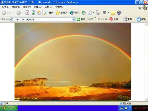
比如,彩虹就是最常见的光的色散现象之一。
当阳光照射到空气中的雨滴时,光线在雨滴内部发生折射和反射,多次折射和反射后的光线从雨滴中射出,就形成了彩虹。
彩虹中从外到内依次排列着红、橙、黄、绿、蓝、靛、紫七种颜色,这正是光的色散的结果。
光的色散在科学研究和实际应用中也具有重要的意义。
在天文学中,通过对恒星发出的光进行色散分析,科学家们可以了解恒星的组成成分和温度等信息。
在光学仪器中,如分光镜,就是利用光的色散原理来分析物质的成分和结构。
在通信领域,光的色散现象也会带来一些问题。
在光纤通信中,由于光信号在光纤中传输时会发生色散,导致信号的失真和衰减,从而影响通信质量。
为了解决这个问题,科学家们研发了各种技术来补偿光的色散,比如色散补偿光纤和色散补偿模块等。
此外,光的色散还与我们的日常生活息息相关。
在摄影中,摄影师们需要了解光的色散原理,以便更好地控制色彩和光线,拍摄出高质量的照片。
在显示技术中,如液晶显示器和等离子显示器,也需要考虑光的色散问题,以提供清晰、准确的色彩显示。
总之,光的色散是光学中一个非常重要的概念,它不仅让我们看到了美丽的彩虹和多彩的世界,还为科学研究和技术发展提供了重要的理论基础和应用价值。
一、红外光学玻璃与红外晶体资料光学特征:1. 晶体资料晶体资料包含离子晶体与半导体晶体离子晶体包含碱卤化合物晶体,碱土—卤族化合物晶体及氧化物及某些无机盐晶体。
半导体晶体包含Ⅳ族单元素晶体、Ⅲ~Ⅴ族化合物和Ⅱ~Ⅵ族化合物晶体等。
离子型晶体往常拥有较高的透过率,同时有较低的折射率,因而反射损失小 ,一般不需镀增透膜,同时离子型晶体光学性能受温度影响也小于非离子型晶体。
半导体晶体属于共价晶体或某种离子耦合的共价键晶体。
晶体的特色是其物理和化学特征及使用特征的多样性。
晶体的折射率及色散度变化范围比其余种类资料丰富得多。
能够知足不一样应用的需要,有一些晶体还具备光电、磁光、声光等效应,能够用作探测器械料。
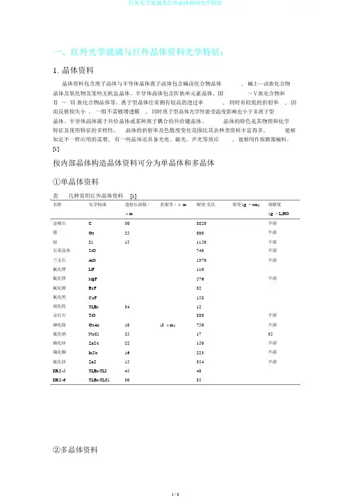
[1]按内部晶体构造晶体资料可分为单晶体和多晶体①单晶体资料表几种常用红外晶体资料[1]名称化学构成透射长波限 /折射率 / μ m硬度/克氏密度/(g ·cm)溶解度μm/(g ·L)HO金刚石C308820不溶锗Ge25800不溶硅Si151150不溶石英晶体SiO740不溶兰宝石AlO1370不溶氟化锂LiF110氟化镁MgF576不溶氟化钡BaF82氟化钙CaF158溴化铊TLBr3412金红石TiO880不溶砷化镓GaAs18(8 μm)750不溶氯化钠NaCl251735硒化锌ZnSe22150不溶锑化铟InSb16223不溶硫化锌ZnS15354不溶KRS-5TLBr-TLI4540KRS-6TLBr-TLCl3035②多晶体资料表红外多晶资料[1]资料透射范围 / μm折射率 /5 μm硬度/克氏熔点/℃密度/(g ·m)在水中溶解度MgF~5761396不溶ZnS~3541020不溶MgO~6402800不溶CaF~2001403微溶ZnSe~22150不溶CdTe2~30401045不溶常用的红外单晶资料包含Ge、Si 、金红石、蓝宝石、石英晶体、ZnS、 GaAs、 MgF、 NaCl 、TlBr 、KHS-6(TlBr-TlCl)和KHS-5(TlBr-TlI)等,拥有熔点高、热稳固性好、硬度高、折射率和色散化范围大等长处,但晶体尺寸受限、成真相对较高。
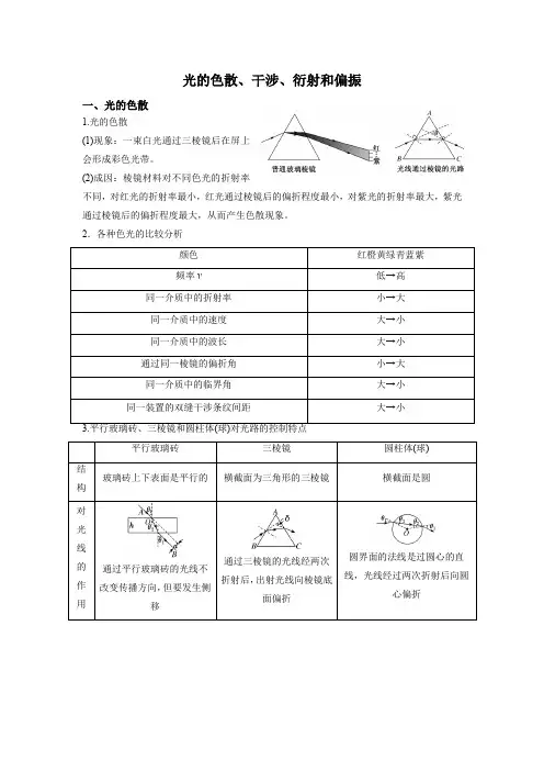
光的色散、干涉、衍射和偏振一、光的色散1.光的色散(1)现象:一束白光通过三棱镜后在屏上会形成彩色光带。
(2)成因:棱镜材料对不同色光的折射率不同,对红光的折射率最小,红光通过棱镜后的偏折程度最小,对紫光的折射率最大,紫光通过棱镜后的偏折程度最大,从而产生色散现象。
2.各种色光的比较分析颜色红橙黄绿青蓝紫频率ν低→高同一介质中的折射率小→大同一介质中的速度大→小同一介质中的波长大→小通过同一棱镜的偏折角小→大同一介质中的临界角大→小同一装置的双缝干涉条纹间距大→小平行玻璃砖三棱镜圆柱体(球)结构玻璃砖上下表面是平行的横截面为三角形的三棱镜横截面是圆对光线的作用通过平行玻璃砖的光线不改变传播方向,但要发生侧移通过三棱镜的光线经两次折射后,出射光线向棱镜底面偏折圆界面的法线是过圆心的直线,光线经过两次折射后向圆心偏折应用测定玻璃的折射率全反射棱镜,改变光的传播方向改变光的传播方向二、光的干涉1.产生干涉的条件两列光的频率相同,振动方向相同,且具有恒定的相位差,才能产生稳定的干涉图样。
2.杨氏双缝干涉(1)原理如图所示。
(2)形成亮、暗条纹的条件①单色光:形成明暗相间的条纹,中央为亮条纹。
光的路程差r2-r1=kλ(k=0,1,2,…),光屏上出现亮条纹。
光的路程差r2-r1=(2k+1)λ2(k=0,1,2,…),光屏上出现暗条纹。
①白光:光屏上出现彩色条纹,且中央亮条纹是白色(填写颜色)。
①条纹间距公式:Δx=ldλ。
3.薄膜干涉的理解和应用(1)形成:如图所示,竖直的肥皂薄膜,由于重力的作用,形成上薄下厚的楔形。
光照射到薄膜上时,在膜的前表面AA′和后表面BB′分别反射回来,形成两列频率相同的光波,并且叠加。
(2)亮、暗条纹的判断①在P1、P2处,两个表面反射回来的两列光波的路程差Δr等于波长的整数倍,即Δr=nλ(n =1,2,3,…),薄膜上出现亮条纹。
①在Q处,两列反射回来的光波的路程差Δr等于半波长的奇数倍,即Δr=(2n+1)λ2(n=0,1,2,3,…),薄膜上出现暗条纹。

光学现象色散和衍射的特性色散和衍射是光学中常见的现象,它们具有一些特殊的特性。
下面就分别介绍色散和衍射的特性。
一、色散的特性色散是指光在经过透明介质时,由于不同波长的光在介质中传播速度不同,产生分散现象。
色散的特性主要包括以下几个方面:1. 色散与光的波长有关:不同波长的光在介质中传播时速度不同,因此产生色散现象。
光的波长越大,色散效应越明显。
2. 色散与介质的折射率有关:介质的折射率越高,光的传播速度越慢,色散效应越明显。
不同介质的色散程度也不同。
3. 色散与入射角有关:光线在介质中入射角度不同,色散现象的程度也不同。
当光线垂直入射时,色散效应最小。
4. 色散与光的波形有关:不同的光波形在介质中传播时,色散的程度也会不同。
例如,白色光在经过三棱镜时,被分解成七种不同颜色的光。
二、衍射的特性衍射是指光通过一个有限孔径或者遇到障碍物时,发生弯曲和扩散的现象。
衍射的特性主要包括以下几个方面:1. 衍射现象与光的波长有关:波长越短,衍射效果越明显。
例如,紫外线的衍射现象比可见光更为显著。
2. 衍射现象与光的传播环境有关:在光线通过狭缝或者孔径时,会发生衍射现象。
例如,光线通过窄缝时,会出现衍射现象,产生衍射图样。
3. 衍射与障碍物的大小有关:障碍物的尺寸越大,衍射效应越显著。
例如,光线通过一个大孔洞时,会出现较明显的衍射现象。
4. 衍射与光的波前有关:光的波前形状会影响衍射现象。
当波前是平面或球面时,衍射程度较小;而当波前是锯齿形或不规则形状时,衍射程度较大。
综上所述,色散和衍射作为光学现象,都具有一些独特的特性。
了解这些特性有助于我们更好地理解和应用光学知识,在实际生活和科学研究中发挥更大的作用。
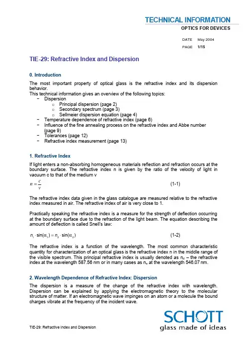
DATE May 2004 PAGE 1/15TIE-29: Refractive Index and Dispersion0. IntroductionThe most important property of optical glass is the refractive index and its dispersion behavior.This technical information gives an overview of the following topics:- Dispersiono Principal dispersion (page 2) o Secondary spectrum (page 3)o Sellmeier dispersion equation (page 4)- Temperature dependence of refractive index (page 6)- Influence of the fine annealing process on the refractive index and Abbe number(page 9)- Tolerances (page 12)- Refractive index measurement (page 13)1. Refractive IndexIf light enters a non-absorbing homogeneous materials reflection and refraction occurs at the boundary surface. The refractive index n is given by the ratio of the velocity of light in vacuum c to that of the medium vvc n =(1-1)The refractive index data given in the glass catalogue are measured relative to the refractive index measured in air. The refractive index of air is very close to 1.Practically speaking the refractive index is a measure for the strength of deflection occurring at the boundary surface due to the refraction of the light beam. The equation describing the amount of deflection is called Snell’s law:)sin()sin(2211αα⋅=⋅n n (1-2)The refractive index is a function of the wavelength. The most common characteristic quantity for characterization of an optical glass is the refractive index n in the middle range of the visible spectrum. This principal refractive index is usually denoted as n d – the refractive index at the wavelength 587.56 nm or in many cases as n e at the wavelength 546.07 nm.2. Wavelength Dependence of Refractive Index: DispersionThe dispersion is a measure of the change of the refractive index with wavelength. Dispersion can be explained by applying the electromagnetic theory to the molecular structure of matter. If an electromagnetic wave impinges on an atom or a molecule the bound charges vibrate at the frequency of the incident wave.DATE May 2004 PAGE 2/15The bound charges have resonance frequency at a certain wavelength. A plot of the refractive index as a function of the wavelength for fused silica can be seen in Figure 2-1. It can be seen that in the main spectral transmission region the refractive index increases towards shorter wavelength. Additionally the dotted line shows the absorption coefficient as a function of the wavelength.Figure 2-1: Measured optical constants of fused silica (SiO 2 glass) [1]2.1 Principal DispersionThe difference (n F – n C ) is called the principal dispersion. n F and n C are the refractive indices at the 486.13 nm and 656.27 nm wavelengths.The most common characterization of the dispersion of optical glasses is the Abbe number. The Abbe number is defined as)/()1(C F d d n n n −−=ν (2.1-1)Sometimes the Abbe number is defined according to the e line as)/()1(C F e e n n n ′′−−=ν (2.1-2).Traditionally optical glasses in the range of νd > 50 are called crown glasses, the other ones as flint glasses.Glasses having a low refractive index in general also have a low dispersion behaviour e.g. a high Abbe number. Glasses having a high refractive index have a high dispersion behaviour and a low Abbe number.DATE May 2004 PAGE 3/152.2. Secondary SpectrumThe characterization of optical glass through refractive index and Abbe number alone is insufficient for high quality optical systems. A more accurate description of the glass properties is achievable with the aid of the relative partial dispersions.The relative partial dispersion P x,y for the wavelengths x and y is defined by the equation:)/()(,C F y x y x n n n n P −−= (2.2-1)As Abbe demonstrated, the following linear relationship will approximately apply to the majority of glasses, the so-called ”normal glasses”d xy xy y x b a P ν⋅+≈, (2.2-2)a xy andb xy are specific constants for the given relative partial dispersion.In order to correct the secondary spectrum (i.e. color correction for more than two wavelengths) glasses are required which do not conform to this rule. Therefore glass types having deviating partial dispersion from Abbe’s empirical rule are especially interesting.As a measure of the deviation of the partial dispersion from Abbe’s rule the ordinate difference ∆P is introduced. Instead of relation (2.2-2) the following generally valid equation is used:y x d xy xy y x P b a P ,,∆+⋅+=ν (2.2-3)The term ∆P x,y therefore quantitatively describes a dispersion behavior that deviates from that of the ”normal glasses.”The deviations ∆P x,y from the ”normal lines” are listed for the following five relative partial dispersions for each glass type in the data sheets.)/()()/()()/()()/()()/,,,,C F g i g i C F F g F g C F e F e F C F s C s C C F t C C,t n n n n P n n n n P n n n n P n n n n P n (n )n (n P −−=−−=−−=−−=−−= (2.2-4)The position of the normal lines is determined based on value pairs of the glass types K7 and F2. The explicit formulas for the deviations ∆P x,y of the above-mentioned five relative partial dispersions are:DATE May 2004 PAGE 4/15)008382.07241.1()/()()001682.06438.0()/()()000526,04884.0()/()()002331.04029.0()/()()004743.05450.0()/()(,,,,,d C F g i g i d C F F g F g d C F e F e F d C F s C s C d C F t C t C n n n n P n n n n P n n n n P n n n n P n n n n P ννννν⋅−−−−=∆⋅−−−−=∆⋅−−−−=∆⋅+−−−=∆⋅+−−−=∆ (2.2-5)Figure 2.2-1 shows the P g,F versus the Abbe number νd diagram.Figure 2.2-1: P g,F as a function of the Abbe number for Schott’s optical glass sortiment.Additionally the normal line is given.The relative partial dispersions listed in the catalog were calculated from refractive indices to 6 decimal places. The dispersion formula (2.3-1) can be used to interpolate additional unlisted refractive indices and relative partial dispersions (see chapter 2.3).2.3. Sellmeier Dispersion EquationThe Sellmeier Equation is especially suitable for the progression of refractive index in the wavelength range from the UV through the visible to the IR area (to 2.3 µm). It is derived from the classical dispersion theory and allows the description of the progression of refractive index over the total transmission region with one set of data and to calculate accurate intermediate values.DATE May 2004 PAGE 5/15)()()(1)(3223222212212C B C B C B n −⋅+−⋅+−⋅=−λλλλλλλ (2.3-1)The determination of the coefficients was performed for all glass types on the basis of precision measurements by fitting the dispersion equation to the measurement values. The coefficients are listed in the data sheets.The dispersion equation is only valid within the spectral region in which refractive indices are listed in the data sheets of each glass. Interpolation is possible within these limits. The wavelengths used in the equation have to be inserted in µm with the same number of digits as listed in Table 2.3-1. For practical purposes Equation 2.3-1 applies to refractive indices in air at room temperature. The achievable precision of this calculation is generally better than 1·10-5 in the visible spectral range. The coefficients of the dispersion equation can be reported for individual glass parts upon request. This requires a precision measurement for the entire spectral region, provided the glass has sufficient transmission.Table 2.3-1: Wavelengths for a selection of frequently used spectral linesDATE May 2004 PAGE 6/153. Temperature Dependence of Refractive IndexThe refractive indices of the glasses are not only dependent on wavelength, but also upon temperature. The relationship of refractive index change to temperature change is called the temperature coefficient of refractive index. This can be a positive or a negative value. The data sheets contain information on the temperature coefficients of refractive index for several temperature ranges and wavelengths. The temperature coefficients of the relative refractive indices ∆n rel /∆T apply for an air pressure of 0.10133·106 Pa. The coefficients of the absolute refractive indices dn abs /dT apply for vacuum.The temperature coefficients of the absolute refractive indices can be calculated for other temperatures and wavelengths values with the aid of equation (3-1).)232(),(21),(),(22102210002TKabs TE E T D T D D T n T n dT T dn λλλλλ−∆⋅⋅++∆⋅⋅+∆⋅⋅+⋅⋅−= (3-1)Definitions:T 0 Reference temperature (20°C) T Temperature (in °C) ∆T Temperature difference versus T 0 λ Wavelength of the electromagnetic wave in a vacuum (in µm) D 0, D 1, D 2, E 0, E 1 and λTK : constants depending on glass typeThis equation is valid for a temperature range from -40°C to +80°C and wavelengths between 0.6438 µm and 0.4358 µm. The constants of the dispersion formula are also calculated from the measurement data and listed on the test certificate.The temperature coefficients in the data sheets are guideline values. Upon request, measurements can be performed on individual melts in the temperature range from -100°C to +140°C and in the wavelength range from 0.3650 µm to 1.014 µm with a precision better than ± 5·10-7/K. The accuracy at the limits of the measurement range is somewhat less than in the middle of this interval.The temperature coefficients of the relative refractive indices ∆n rel /∆T and the values for ∆n abs can be calculated with the help of the equations listed in Technical Information TI Nr. 19 (available upon request).Figures 3-1 to 3-4 show the absolute temperature coefficient of refractive index for different glasses, temperatures and wavelengths.DATE May 2004 PAGE 7/15DATE May 2004PAGE 8/15SF 6.DATE May 2004 PAGE 9/154. Influence of the Fine Annealing Process on the Refractive Index and Abbe numberThe optical data for a glass type are chiefly determined by the chemical composition and thermal treatment of the melt. The annealing rate in the transformation range of the glass can be used to influence the refractive index within certain limits (depending on the glass type and the allowable stress birefringence). Basically slower annealing rates yield higher refractive indices. In practice, the following formula has proven itself.)/log()()(00h h m h n h n x nd d x d ⋅+= (4-1) h 0 Original annealing rate h x New annealing rate m nd ? Annealing coefficient for the refractive index depending on the glass typeThe refractive index dependence on annealing rate is graphically shown in Figure 4-1.Figure 4-1: Dependence of refractive index on the annealing rate for several glass types. Reference annealing rate is 7 K/hAn analogous formula applies to the Abbe number.)/log()()(00h h m h h x d d x d ⋅+=ννν (4-2) m νd ? Annealing coefficient for the Abbe number depending on the glass typeThe annealing coefficient m νd can be calculated with sufficient accuracy with the following equation:)/())((0C F nC nF d nd d n n m h m m −⋅−=−νν (4-3)The coefficient m nF-nC has to be determined experimentally.DATE May 2004 PAGE 10/15Figure 4-2 shows that individual glass types vary greatly in their dependence of t he Abbe number on the annealing rate. In general also the Abbe number increases with decreasing annealing rate. High index lead free glass types like N-SF6 show anomalous behavior. Anomalous behaviour means that the Abbe number decreases with decreasing annealing rate.Figure 4-2: Abbe number as a function of the annealing rate for several glass types. Reference annealing rate is 7 K/hValues for Annealing coefficients of some optical glasses are shown in Table 4-1. We will provide the values for the annealing coefficients of our glasses upon request.m nd m nF-nc m νdN-BK7 -0.00087 -0.000005 -0.0682 N-FK51 -0.00054 -0.000002 -0.0644 SF 6 -0.00058 +0.000035 -0.0464 N-SF6 -0.0025 -0.000212 0.0904Table 4-1: Annealing coefficients for several selected glass typesThe annealing rate can be used to adjust the refractive index and Abbe number to the desired tolerance range.In practice the annealing rate influences the refractive index and the Abbe number simultaneously. Figure 4-3 shows a diagram of the Abbe number versus the refractive index for N -BK7. The rectangular boxes indicate the tolerance limits (steps) for the refractive index and the Abbe number. For example the largest box with a dotted frame indicates the tolerance borders for step 3 in refractive index and step 4 in Abbe number. The smallest box indicates step 1 in refractive index and Abbe number. In the center of the frames is the nominal catalog value.DATE May 2004PAGE 11/15 After melting the optical glass is cooled down at a high annealing rate. To control the refractive index during the melting process samples are taken directly from the melt after each casting. These samples are cooled down very fast together with a reference sample of the same glass. The reference sample has a known refractive index at an annealing rate of 2°C/h. By measuring the change in refractive index of the reference sample the refractive index of the sample can be measured with moderate accuracy in the range of ±10-4.The annealing rate dependence of the Abbe number and refractive index of each glass is represented by a line in the diagram having a slope that is characteristic for the glass type. For a given melt the position of the line in the diagram is given by the initial refractive index / Abbe number measurement for a cooling rate of 2°C/h as a fix-point together with the glass typical slope. The refractive index and Abbe number for a given glass part can be adjusted by a fine annealing step along this characteristic line.Glass for cold processing has to be fine annealed to reduce internal stresses. During this fine annealing the annealing rate is in general lower than 2°C/h. The initial refractive index has to be adjusted during melting in such a way that the desired tolerances can be reached during fine annealing. The initial refractive index of N-BK7 for example is in general lower than the target value.Figure 4-3:The influence of the annealing rate on the refractive index and Abbe numberof N-BK7 for different initial refractive indices.DATE May 2004PAGE 12/15 Glass for hot processing i.e reheat pressing is subjected to much more rapid annealing. The heat treatment processes used by the customer in general use annealing rates much higher than 2°C/h. Therefore for N-BK7 pressings for example the initial refractive index needs to be higher than the target value. For a better visualization in figure 4-3 the annealing line for pressings was shifted to higher Abbe numbers. In general it is also possible to achieve step 1/1 for pressings after hot processing. We deliver an annealing schedule for each batch of glass for hot processing purpose. This annealing schedule contains the initial refractive index at 2°C/h and the limit annealing rates to stay within the tolerances.5. TolerancesThe refractive indices, which are listed to 5 decimal places in the data sheets, represent values for a melt with nominal n d-νd position for the glass type in question. The refractive index data are exact to five decimal places (for λ > 2 µm: ± 2·10-5). The accuracy of the data is less in wavelength regions with limited transmission. All data apply to room temperature and normal air pressure (0,10133·10-6 Pa).Defining tolerances for the refractive index of a glass the customer has to distinguish between the refractive index tolerance, the tolerance of refractive index variation within a lot and the refractive index homogeneity (figure 5-1).Figure 5-1:Refractive index variation from within a production sequence.DATE May 2004 PAGE 13/15All deliveries of fine annealed block glass and fabricated glass are made in lots of single batches. The batch may be a single block or some few strip sections. More information on the new lot id system can be found in [3].The refractive index and Abbe number tolerance is the maximum allowed deviation of a single part within the delivery lot from nominal values given in the data sheets of the catalog. The refractive index of the delivery lot given in the standard test certificates is given by the following formulae:2/)(min max n n n lot += (5-1)n max is the maximum and n min the minimum refractive index within the lot.The refractive index variation from part to part within a lot is always smaller than ± 1*10-4. The refractive index homogeneity within a single part is better than ± 2*10-5 in general [4]. A short summary of the refractive index tolerance, variation and homogeneity grades can be found in table 5-1. More information is given in the optical glass catalogue [5].Tolerance Grade Refractive Index [*10-5] Abbe NumberStep 4-- ± 0.8% Step 3 ± 50 ± 0.5% Step 2 ± 30 ± 0.3% AbsoluteStep 1± 20 ± 0.2% SN± 10 -- S0 ± 5 -- Variation S1± 2 -- H1± 2 -- H2 ± 0.5 -- H3 ± 0.2 -- H4 ± 0.1 -- Homogeneity H5 ± 0.05--Table 5-1: Refractive Index Tolerances6. Refractive Index MeasurementFor refractive index measurement two different measurement setups are used: the v -block refractometer (figure 6-2) and the spectral goniometer. Figure 6-1 shows the principle of the v-Block measurement. The samples are shaped in a nearly square shape. One sample is about 20x20x5 mm small. The sample will be placed in a v shaped block prism. The refractive index of this prism is known very precisely. The refraction of an incoming light beam depends on the refractive index difference between the sample and the v-block-prism. The advantage of this method is that up to 10 samples can be glued together into one v -block stack. Therefore many samples can be measured in a very short time. The relative measurement accuracy is very h igh, therefore differences in refractive index within one v -block stack can be measured very accurately.DATE May 2004 PAGE 14/15Figure 6-1: Refractive index variation from within a production sequence .Figure 6-2: V-block refractometer.The spectral goniometric method is based on the measurement of the angle of minimum refraction in a prism shaped sample. This is the most accurate absolute refractive index measurement method. In our laboratory we have standard manual spectral goniometers and automated improved spectral goniometer with higher accuracy and the ability to measure in the infrared and UV region (figure 6-3).Figure 6-3: Manual spectral goniometer (left side), automated spectral goniometer (rightside).sample with lowerrefractive indexsample with higher refractive index samplev-block-prism immersion oillightbeamDATE May 2004PAGE 15/15 Table 6-1 shows a summary of the refractive index measurements available at Schott.Measurement accuracyMeasurementRefractive index DispersionWavelengths MethodV-block standard ± 30*10-6 ± 20*10-6g, F’, F, e, d, C’,CV-block enhanced ± 20*10-6± 10*10-6I, h, g, F’, F, e, d,C’, C, r, tv-blockrefractometerPrecisionspectrometer± 10*10-6± 3*10-6Super precision spectrometer ± 5*10-6± 2*10-6h, g, F’, F, e, d,C’, CspectralgoniometerUV precisionspectrometer± 10-20*10-6± 3*10-6UV super precision spectrometer ± 2-5*10-6± 2*10-6248.3 nm –2325.4 nm(about 30spectral linespossible)automaticspectralgoniometerTable 6-1: Absolute refractive index measurement accuraciesThe temperature coefficient of refractive index is measured using an automated spectral goniometer and a temperature controlled climate chamber with a temperature range from -100°C up to +140°C. The temperature coefficient can be measured with an accuracy of ± 0.5*10-6 K-1.7. Literature[1] The properties of optical glass; H. Bach & N. Neuroth (Editors), Springer Verlag 1998[2] SCHOTT Technical Information No. 19 (available upon request).[3] SCHOTT Technical Note No. 4: Test report for delivery lots[4] SCHOTT Technical Information No. 26: Homogeneity of optical glass[5] SCHOTT Optical Glass Pocket CatalogueFor more information please contact:Optics for DevicesSCHOTT GlasGermanyPhone: + 49 (0)6131/66-3835Fax: + 49 (0)6131/66-1998E-mail: info.optics@/optics_devices。

光学中的光的色散光的色散是光学中一种重要的现象,它描述了光在通过介质时,不同波长的光被折射的角度不同的现象。
光的色散现象可以分为正常色散和反常色散两种。
在本文中,我们将详细探讨光的色散现象,包括其原理、应用以及对光学领域的重要性。
一、光的色散原理光的色散原理是由光的折射率与波长之间的关系导致的。
根据斯涅尔定律,光在介质中传播时会发生折射,而介质的折射率与光的波长有关。
通常来说,折射率对于不同的波长是不同的,因此,当光通过介质时,不同波长的光线会以不同的角度折射出来,从而产生色散现象。
在一般情况下,光在经过介质后,折射角度与入射角度之间的关系可以用斯涅尔定律来描述:n1*sin(θ1) = n2*sin(θ2)其中,n1和n2分别代表了入射介质和折射介质的折射率,θ1和θ2分别为入射角和折射角。
二、正常色散和反常色散根据光的色散特性,我们可以将色散现象分为正常色散和反常色散两种。
1. 正常色散正常色散是指当光从真空进入具有折射率大于1的介质中时,折射角度随着波长的增加而增大的现象。
常见的例子是光经过玻璃体时,不同颜色的光线会以不同的折射角度折射出来,从而形成七彩光谱。
2. 反常色散反常色散则是指当光从真空进入具有折射率小于1的介质中时,折射角度随着波长的增加而减小的现象。
这种现象在一些特殊的介质中发生,例如当光从水进入冰中时,不同颜色的光线会以相反的折射角度折射出来。
三、光的色散应用光的色散现象在科学研究和工程应用中具有广泛的应用价值,下面我们将介绍其中的几个方面。
1. 分光仪分光仪是一种利用光的色散原理来分离混合光的仪器。
它通过将光线经过棱镜或光栅等光学器件,使得不同波长的光线以不同的角度折射出来,从而实现对光谱的分离。
分光仪被广泛应用于化学分析、物质鉴定、天文观测等领域。
2. 光纤通信光纤通信是一种利用光作为信息传输的技术。
在光纤中,光信号会通过不同的波长来传输信息,而不同波长的光信号会以不同的速度传播。

光学器件中的色散特性分析在光学领域中,色散指的是光波在经过光学器件(例如透镜、棱镜等)时,不同波长的光分离成不同的角度或位置。
光波的色散性质对于许多应用至关重要,例如成像、分光和光通信等。
1. 色散的基本原理色散的基本原理源于光波在透明媒介中不同频率的折射率不同。
根据光传播的速度和频率之间的关系,可以推导出光的折射率随频率变化的规律。
这种频率-折射率关系通常用色散曲线或折射率曲线表示。
2. 色散种类色散可以根据折射率与频率的关系分为正常色散和反常色散两种。
正常色散指的是折射率随频率增加而递增,而反常色散则是折射率随频率增加而递减。
此外,还有角色散和色散的分类。
角色散是指入射光斜入射透镜或棱镜时产生的色散效应,而色散则是垂直入射时的效应。
3. 色散的影响在光学系统中,色散可以造成图像模糊、色彩偏移等问题。
对于光通信系统来说,色散会导致光脉冲的扩散,降低传输速率和距离。
为了解决色散带来的问题,科学家和工程师采用了多种方法来补偿色散。
其中一种常见的方法是使用色散补偿光纤,该光纤具有特殊结构,能够在光信号传输过程中抵消色散带来的影响。
4. 色散的应用色散的特性在许多光学器件中都有重要的应用。
例如,在分光仪中,利用色散的原理可以将不同波长的光分离出来,实现光谱分析。
在摄影领域,色散的特性被用于消除色差,保证图像的准确还原。
此外,色散的应用还涉及光纤通信、光纤传感、光计算等领域。
研究和控制色散的性质对于改善光学器件的性能和创新新的应用具有重要意义。
5. 色散特性分析方法为了分析光学器件中的色散特性,科学家和工程师使用了多种方法和技术。
其中一种常见的方法是使用光谱仪,通过测量不同波长光的位置或角度变化,来确定色散的程度和类型。
此外,还有一种称为径向载波神经网络(Radial basis function neural network)的方法,它可以在没有实际测量数据的情况下,通过建立模型来预测色散效应。
总结:色散作为光学器件中一个重要的特性,对于很多光学应用起着关键的作用。

光的色散现象色散是一种自然现象,指的是光在透过介质时会因折射率的不同而导致光的波长发生变化。
光的色散现象一直以来都引起科学家的兴趣和探索。
本文将介绍光的色散现象的原理、应用和未来发展。
一、色散现象的原理光的色散现象可以通过折射率的不同来解释。
折射率是介质表征光传播速度的性质,不同波长的光在介质中有不同的速度。
由于折射率与波长之间存在关系,光在透过介质时会发生波长的变化,导致不同波长的光分离开来。
以光在玻璃棱镜中的色散现象为例。
当白光通过玻璃棱镜时,不同颜色的光会以不同角度折射出来,形成一束分散的光谱。
这是因为不同波长的光在玻璃中传播速度不同,因而发生不同程度的折射。
二、色散现象的应用光的色散现象在实际中有很多应用。
下面将介绍其中两个重要的应用。
1. 光谱学光谱学是研究光的色散现象的学科,利用不同波长光的分离来研究物质的结构和性质。
光谱学可以通过分析光谱来推断物质的成分,由此在化学分析、天文学和物理学等领域发挥着重要的作用。
例如,通过观察恒星的光谱,天文学家可以了解恒星的化学成分和状态。
光谱学还用于分析复杂化合物的结构,揭示其中的分子间相互作用和化学键形成的方式。
2. 精密测量光的色散现象可以用于测量光的波长,进而实现精密测量。
例如,干涉仪就是利用光的色散现象来测量极小的位移或厚度差。
干涉仪是由一束光经过分割成两束,分别通过不同的路径再次合并生成干涉条纹的设备。
通过观察干涉条纹的位置和变化,可以计算出测量物体的波长、发生位移或厚度差等重要参数,广泛应用于科学研究和工程领域。
三、光的色散现象的未来发展光的色散现象一直是光学领域的重要研究方向,随着科技的进步,光的色散现象也有了新的发展和应用。
1. 光通信光通信是利用光传输信息的技术。
由于光的波长比电磁波要短,因此光信号可以携带更多的信息,具有更高的传输速率。
然而,光在传输中也会发生色散现象,导致信号的扩展和失真。
为了克服光的色散问题,科学家们研发出了各种修正色散的方法,如光纤光栅和色散补偿器等。

光的色散与衍射现象高一物理光学色散衍射现象知识的深入学习与运用在物理学中,光的色散与衍射现象是光学领域中的两个重要概念。
本文将对光的色散与衍射现象进行深入学习与运用。
一、光的色散光的色散是指光在传播过程中,由于折射率与波长之间的关系不同而产生的现象。
当光经过介质的界面时,不同波长的光会按照一定角度折射,导致光的分离现象。
这种现象在自然界和日常生活中都有广泛的应用。
1. 原理与机制根据菲涅耳衍射公式,光在介质中的传播速度与介质的折射率有关,而折射率与波长之间存在一定的关系。
根据斯内尔定律,当光由一种介质射向另一种介质时,介质的折射率愈大,光线的弯曲角度就愈大。
因此,当不同波长的光通过介质界面时,由于它们的折射率不同,会产生不同的折射角,从而导致光的色散现象。
2. 色散的实例光的色散现象广泛存在于自然界和日常生活中。
例如,彩虹的出现就是光的色散现象的一个经典例子。
当阳光照射到空气中的水滴上并经过折射和反射后,不同波长的光被分离出来,形成了七彩的光谱。
此外,光的色散现象还广泛应用于光谱分析、光学仪器、光通信等领域。
二、光的衍射现象光的衍射是指光在通过一个孔径较小或物体边缘时发生的干涉现象。
衍射现象是波动光学的重要内容,对于了解光的传播和干涉现象具有重要意义。
1. 原理与机制光的衍射现象可以利用惠更斯-菲涅尔原理进行解释。
根据惠更斯-菲涅尔原理,每个点上的波前可以被认为是源点,这些源点发出球面波。
当这些球面波经过孔径或物体时,会形成一系列的波前,这些波前之间会发生干涉,从而产生衍射现象。
2. 衍射的实例光的衍射现象也广泛存在于自然界和日常生活中。
例如,当光通过窄缝或狭缝时,会出现经典的单缝衍射现象,光线会在后方形成一系列明暗相间的条纹。
另外,光的衍射也可以在天文学中观测到,例如恒星的光通过地球大气层时发生的大气衍射现象。
三、光的色散与衍射的实际应用光的色散与衍射现象在科学和工程技术领域有着广泛的应用。
1. 光谱分析光的色散现象被广泛应用于光谱分析。

光学知识点光的色散现象光学知识点:光的色散现象在我们日常生活中,光的色散现象无处不在,却常常被我们所忽视。
当阳光穿过三棱镜,或者雨后天空中出现的彩虹,这些都是光的色散现象的生动展示。
那么,究竟什么是光的色散现象呢?让我们一起来深入了解一下。
光的色散,简单来说,就是指一束白光通过某种介质后,被分解成不同颜色光的现象。
这些不同颜色的光按照一定的顺序排列,形成了我们所熟知的红、橙、黄、绿、蓝、靛、紫七种颜色的光谱。
要理解光的色散现象,首先得明白光是一种电磁波。
白光并不是单一的颜色,而是由多种不同波长的单色光混合而成。
而不同波长的光在介质中的传播速度是不同的。
以三棱镜为例,当白光进入三棱镜时,由于玻璃对不同波长的光具有不同的折射率,这就导致了不同颜色的光在三棱镜中的折射角度不同。
波长较长的红光折射角度较小,而波长较短的紫光折射角度较大。
因此,当这些光从三棱镜的另一侧射出时,它们就被分离开来,形成了色彩斑斓的光谱。
雨后的彩虹也是光的色散现象的一个经典例子。
当阳光照射到空气中的雨滴时,光线会在雨滴内部发生折射和反射。
这就相当于光线在一个个微小的三棱镜中传播,从而被分解成不同颜色的光。
我们从特定的角度观察,就能看到美丽的彩虹。
光的色散现象不仅具有美丽的视觉效果,在科学和技术领域也有着广泛的应用。
在光学仪器中,如分光镜,就是利用光的色散原理来分析物质的成分和结构。
通过观察物质发出或吸收的光谱,科学家可以确定物质中所含的元素和化合物。
在摄影中,摄影师可以利用滤光片来选择特定波长的光,以达到特定的拍摄效果。
比如,使用红色滤光片可以增强红色物体的对比度,使拍摄效果更加突出。
在通信领域,光纤通信也与光的色散现象密切相关。
由于光在光纤中传播时会发生色散,导致信号的失真和衰减。
为了解决这个问题,科学家们研发出了各种技术来补偿色散的影响,提高通信质量和传输距离。
在日常生活中,我们也能感受到光的色散现象带来的影响。
比如,我们在购买宝石时,宝石的颜色和光泽往往与光的色散有关。
光的色散与衍射原理在日常生活中,我们经常能够观察到光的一些特殊现象,比如彩虹的出现以及光线通过狭缝或孔径的衍射等等。
这些现象的产生与光的色散与衍射原理密切相关。
本文将深入探讨光的色散与衍射原理,并解释其背后的物理原理。
一、光的色散原理色散是指在一定的介质中,光的不同波长在经过折射或反射后发生偏离的现象。
要理解色散的原理,我们首先需要了解光的波动性质。
1.1 光的波动性质根据光的波动学理论,光是由电磁波组成的,具有波长和频率。
在真空中,光的速度是一个常数,即光速$c$,波长与频率之间存在以下关系式:\[c = \lambda \times f\]其中,$c$代表光速,$\lambda$代表波长,$f$代表频率。
1.2 光的折射与反射当光从一种介质(如空气)射入另一种介质(如玻璃)时,由于介质的折射率不同,光的速度也会发生改变。
这时光线会发生折射或反射。
根据斯涅耳定律,光线在平面界面上的折射角$\theta_1$与入射角$\theta_2$之间存在关系:\[n_1\sin\theta_1 = n_2\sin\theta_2\]其中,$n_1$和$n_2$代表两种介质的折射率。
1.3 光的色散现象当光通过具有色散性质的介质时,不同波长的光将会因为折射率的不同而发生偏离。
这样,就能够观察到光的色散现象。
最常见的色散现象之一就是彩虹的产生。
彩虹是当阳光通过雨滴折射、反射、衍射后形成的一种美丽光谱。
阳光中的白光其实是由多种波长的光组成的,经过雨滴的折射与反射后,不同波长的光就会因为折射率的不同而发生偏离,从而形成七彩的光谱。
二、光的衍射原理衍射是指光通过狭缝、孔径或物体边缘时会发生波的弯曲和扩散现象。
下面我们来具体了解光的衍射原理。
2.1 光的波动性质再探光的波动性质决定了它可以发生衍射现象。
根据惠更斯-菲涅尔原理,当光通过一个狭缝或孔径时,每个点都可以看作是次波源,次波源的光波经过衍射后会相互叠加形成新的波前。
光学中的色散与衍射现象分析光学作为一门研究光和光学现象的科学,包含着丰富的现象和理论。
其中,色散与衍射是两个重要的现象,在光学研究和应用中起着重要的作用。
一、色散现象的分析色散是指光在通过透明介质时,不同波长的光的折射率不同而产生的偏离现象。
光的频率与波长存在着确定的关系,因此波长不同的光在经过透明介质时会按不同的角度发生折射,并且分离成不同的颜色。
色散现象的最常见例子就是光在经过三棱镜时的折射和分散。
根据光的折射定律和菲涅尔公式,可以计算出不同波长的光在介质中的折射角,并得出各个波长光的折射率。
从而在观察到一束经过三棱镜的白光时,可以看到白光分解成七个颜色,即红橙黄绿青蓝紫七种颜色,这就是色散现象。
色散现象不仅在自然界中普遍存在,还被广泛应用于光学仪器和光学技术中。
例如,在光谱仪中,利用色散原理可以将光分解成各个波长的成分,实现精确的光谱测量和分析。
而在光纤通信中,利用光纤中光信号在不同波长下的传播速度不同,可以实现波分复用技术,提高光信号传输的带宽和效率。
二、衍射现象的分析衍射是指光通过一个孔或者绕过一个物体时,出现偏离直线传播的现象。
在衍射过程中,光束被散射成若干个新的次级波,这些次级波沿不同的方向传播,并在干涉区域形成明暗相间的衍射图样。
衍射现象的经典实验是夫琅和费衍射,它利用一个狭缝让光通过,观察到狭缝后的干涉图样。
实验结果显示,在适当的条件下,光通过狭缝后会形成一系列的明暗条纹,这就是衍射现象的直观表现。
衍射现象是光的波动性质的重要表现,它揭示了光是一种波动性质的电磁辐射。
而且,衍射现象的研究推动了现代光学的发展和应用,例如在显微镜和望远镜中,衍射效应决定了成像的分辨率和清晰度;在激光和光存储技术中,衍射光栅可以实现光的精确操控和信息记录。
总结起来,光学中的色散与衍射现象是两个重要且相互关联的现象。
色散描述了光在介质中波长不同而折射率不同的特性,而衍射则揭示了光的波动性质和干涉现象。
光学玻璃中Pt闪点的结构特征及其形成机理王衍行;许晓典;祖成奎;何坤;周鹏【期刊名称】《功能材料》【年(卷),期】2017(048)003【摘要】SiO2-B2O3-Ta2O5-ZrO2-Na2O系统光学玻璃因具有较大的相对部分色散偏离值、良好化学稳定性和可加工性等特点而备受关注.作者采用分光光度计、光学显微镜、扫描电镜及能谱等方法系统研究了光学玻璃中Pt闪点结构特征及其形成机理.Pt坩埚制备的光学玻璃在紫外区存在明显吸收,且吸收曲线向长波方向移动,这是由于玻璃中Pt4+离子吸收峰所致.Pt闪点存在形式多样,大小不一,尺寸主要在20 μm以下.SiO2-B2O3-Ta2O5-ZrO2-Na2O系统玻璃中Pt闪点的影响因素主要有组分中高含量高键强离子Ta5+和Zr4+、低玻璃粘度和熔体降温处理等.【总页数】5页(P78-82)【作者】王衍行;许晓典;祖成奎;何坤;周鹏【作者单位】中国建筑材料科学研究总院,北京 100024;中国建筑材料科学研究总院,北京 100024;中国建筑材料科学研究总院,北京 100024;中国建筑材料科学研究总院,北京 100024;中国建筑材料科学研究总院,北京 100024【正文语种】中文【中图分类】TQ171【相关文献】1.基于光电放大器OPT101的石油闪点信号检测和提取方法 [J], 俞涛;林晓珑;王军;赵静荣2.光学玻璃钻削时孔口损伤的形成机理及抑制工艺 [J], 马利杰;刘红文;屈海涛;王占奎;苏建修3.富县地区长8致密砂岩储层孔隙结构特征及形成机理 [J], 于春勇4.旋转超声锯切光学玻璃的表面形成机理研究 [J], 沈剑云;朱旭;宋伟;陈剑彬;吴海融;吴贤5.基于1stOpt求解光学玻璃折射率温度系数经验公式常量的方法 [J], 马志远;王鹏飞;吴志强;吴德林;粟勇因版权原因,仅展示原文概要,查看原文内容请购买。
特殊色散玻璃及其应用研究∗王衍行;祖成奎;许晓典;周鹏;何坤【摘要】Special dispersion glass is thought to be a great potential material for long focus,wild field and high precision optical system because of its special optical parameter,excellent transmission and high deviation of the relative partial dispersion.The special dispersion nature aroused by inherent absorption in the ultraviolet and in-frared regions and its progress of the native and foreign were reviewed.The typical application of special disper-sion glass for lens material in advanced optical system to revise secondary spectrum was introduced.In addition, the prospect of special dispersion glass was outlined.%特殊色散玻璃是一类偏离正常线较远的光学玻璃,具有特定光学常数、高度透光性和较大相对部分色散偏离值,被视为长焦距、大视场和高精度光学系统设计的关键优选材料。
作者总结了光学玻璃的特殊色散本质,认为其是由紫外和红外本征吸收引起的。
综述了特殊色散玻璃的研究进展,并指出了国内外差距。
介绍了特殊色散玻璃作为透镜材料在高品质光学系统中的典型应用,以消除二级光谱。
光的色散现象光,是我们日常生活中非常常见的一种现象。
我们可以用它照亮黑暗的夜晚,可以借助它看清远处的景物,也可以通过它来欣赏美丽的彩虹。
然而,当我们经过一个玻璃棱镜或水晶体时,可能会注意到光的一个特殊现象——色散现象。
色散现象是指白光经过一定的介质后分解成多种不同颜色的光。
这是因为不同颜色的光在介质中的传播速度不同,从而导致折射角度不同,产生了色散。
我们可以通过实验来证明这一点。
首先,我们需要一个三角形的玻璃棱镜。
将白色光束照射到棱镜上,我们会观察到光束射入棱镜后发生了偏折的现象。
而当光线再次射出棱镜时,我们会发现光束被分解成了七种不同颜色的光,即红、橙、黄、绿、蓝、靛、紫。
为什么白光会发生色散呢?这涉及到光的波长和介质的折射率之间的关系。
不同颜色的光具有不同的波长,而介质的折射率则决定了不同颜色的光在介质中的传播速度。
根据斯涅尔定律,光线在通过两个介质的界面时会发生折射,并且入射角和折射角之间满足一个特定的关系。
由于不同波长的光在介质中的传播速度不同,它们在入射角和折射角之间存在着差异,从而导致了光的分解和色散现象的发生。
色散现象不仅仅出现在玻璃棱镜中,我们在日常生活中也会遇到。
例如,当阳光穿过一片雨滴时,会被分解成七彩的光环,形成美丽的彩虹。
这是因为雨滴作为一个小的水珠,在太阳光照射下形成了一个类似棱镜的作用。
光线在雨滴内部不断发生折射和反射,最终形成了彩虹的奇妙景象。
除了自然界中的色散现象,我们还可以通过人工手段来制造色散效果。
例如,在摄影领域,我们通常会使用彩色滤镜来调整光的色彩。
当光线经过彩色滤镜时,只有特定颜色的光通过,其他颜色的光被滤镜吸收或反射。
这样,我们可以通过选择不同的滤镜来改变照片的色调和效果。
光的色散现象不仅有实际应用,而且在科学研究中也有着重要的意义。
例如,在天文学领域,我们可以通过研究恒星的光谱来获取关于宇宙中物质的信息。
当太阳或其他恒星的光通过大气层的阻挡后,会发生色散,并产生各种颜色的光谱线。