RFP 原版宣传材料
- 格式:ppt
- 大小:12.02 MB
- 文档页数:40


项目需求建议书(RFP)本文是关于项目需求建议书(RFP)的说明。
在A部分,提供了项目名称、客户名称、项目经理以及项目发起人姓名等一般信息。
B部分描述了项目的目标,包括完成项目的时间、质量要求等方面的信息。
C部分详细描述了执行项目的具体工作。
D部分描述了执行项目的阶段和完成项目任务的主要交付结果等方面的信息。
E部分描述了使用哪种性质的合同。
F部分描述了付款方式,包括付款的时间、金额、币种、方式等。
G部分描述了建议书应包括的具体内容。
H部分描述了评价建议书的主要标准,包括价格、技术方案、项目管理方法、经验与资质等方面。
I部分描述了建议书的截止日期、提交的地点等信息。
另外,本文还包括了项目授权书和项目计划文件。
在项目授权书中,提供了项目的工作任务、被任命的项目经理的姓名、项目经理的职责、权力等方面的信息。
在项目计划文件中,提供了项目名称、客户名称、项目经理以及项目发起人姓名等一般信息,并列出了项目执行过程中涉及的相关人员的信息。
此外,还提供了供应商/分承包商的信息。
总体而言,本文提供了关于项目需求建议书、项目授权书和项目计划文件的详细说明,包括项目的一般信息、目标、工作描述、可交付结果、合同类型、付款方式、建议书的内容、评价标准、提交要求等方面的信息。
项目需求文件A。
项目信息本项目旨在解决以下业务需求或难题,并完成下列工作任务,达成项目目标。
项目管理采用的方法、技术要求、人员签名以及项目计划文件汇总等信息也将在本文件中提供。
项目名称:项目经理:项目发起人:客户名称:文件起草人:B。
业务需求/难题本项目需要解决的业务需求或难题为:C。
工作任务详细描述需要完成的工作任务:D。
项目目标本项目的目标为:工期要求:成本要求:质量性能要求:工作范围要求:E。
项目管理方法本项目管理采用的战略、遵循的流程以及使用的工具等信息为:F。
技术要求本项目的技术要求包括:技术参数:性能指标:设计要求:实施规范:技术方面的培训计划:G。
【推荐下载】奥林巴斯广告词-实用word文档
本文部分内容来自网络,本司不为其真实性负责,如有异议或侵权请及时联系,本司将予以删除!
== 本文为word格式,下载后可随意编辑修改! ==
奥林巴斯广告词
1.內衣外穿不是從瑪丹娜開始的
2. 清早这些个时辰,救济所里冰冷刺骨,
3. 骨瘦如材的饥孩的呻吟声和他们父母的残喘混在一起。
4. 一股恶臭。
你想吐。
但你却抓起你的相机拍了一张。
5. 你的眼睛刚适应这里的黑暗,你就被眼前所见吓得倒退2步,
6. 哦,说不定你是后退取景?
7. 你的胸膛开始燃烧负罪感和正义的火焰?
8. 还有什么没拍到?
9. 如果被你拍下来,你为着什么卖掉照片?
10. 为了响誉世界的声名?还是钞票?你一张照片卖的票子,可是能让非洲的一家大小过一整年的温饱日子。
11. 或者你的目的是要西方各国首脑睁眼看看这场真正的饥荒?
12. 你如何让自己心安理得?因为有件事你一直清楚,
13. 你有英格兰可以回去,有以后可以舒服打发,
14. 而这个女孩留在这里奄奄一息就要死去。
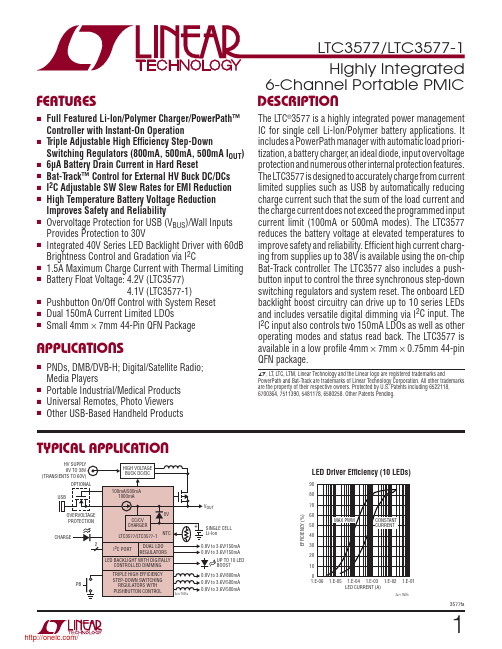
13577faT YPICAL APPLICATIONF EATURESA PPLICATIONSD ESCRIPTION 6-Channel Portable PMIC The L TC ®3577 is a highly integrated power management IC for single cell Li-Ion/Polymer battery applications. It includes a PowerPath manager with automatic load priori-tization, a battery charger , an ideal diode, input overvoltage protection and numerous other internal protection features. The L TC3577 is designed to accurately charge from current limited supplies such as USB by automatically reducing charge current such that the sum of the load current and the charge current does not exceed the programmed input current limit (100mA or 500mA modes). The L TC3577 reduces the battery voltage at elevated temperatures to improve safety and reliability. Effi cient high current charg-ing from supplies up to 38V is available using the on-chip Bat-T rack controller . The L TC3577 also includes a push-button input to control the three synchronous step-down switching regulators and system reset. The onboard LED backlight boost circuitry can drive up to 10 series LEDs and includes versatile digital dimming via I 2C input. The I 2C input also controls two 150mA LDOs as well as other operating modes and status read back. The L TC3577 is available in a low profi le 4mm × 7mm × 0.75mm 44-pin QFN package.LED Driver Effi ciency (10 LEDs)nFull Featured Li-Ion/Polymer Charger/PowerPath™ Controller with Instant-On Operation n T riple Adjustable High Effi ciency Step-DownSwitching Regulators (800mA, 500mA, 500mA I OUT )n 6μA Battery Drain Current in Hard Reset n Bat-T rack™ Control for External HV Buck DC/DCs n I 2C Adjustable SW Slew Rates for EMI Reduction n High Temperature Battery Voltage Reduction Improves Safety and Reliability n Overvoltage Protection for USB (V BUS )/Wall Inputs Provides Protection to 30Vn Integrated 40V Series LED Backlight Driver with 60dB Brightness Control and Gradation via I 2Cn 1.5A Maximum Charge Current with Thermal Limiting n Battery Float Voltage: 4.2V (L TC3577) 4.1V (L TC3577-1)n Pushbutton On/Off Control with System Reset n Dual 150mA Current Limited LDOs n Small 4mm × 7mm 44-Pin QFN PackagenPNDs, DMB/DVB-H; Digital/Satellite Radio; Media Playersn Portable Industrial/Medical Products n Universal Remotes, Photo Viewers n Other USB-Based Handheld ProductsL , L T , L TC, L TM, Linear Technology and the Linear logo are registered trademarks andPowerPath and Bat-T rack are trademarks of Linear Technology Corporation. All other trademarks are the property of their respective owners. Protected by U.S. Patents including 6522118, 6700364, 7511390, 5481178, 6580258. Other Patents Pending.LED CURRENT (A)20E F F I C I E N C Y (%)30506080901.E-061.E-051.E-04 1.E-03 1.E-02 1.E-013577 TA01b1070400/TABLE OF CONTENTSFeatures (1)Applications (1)Typical Application (1)Description (1)Absolute Maximum Ratings (3)Order Information (3)Pin Confi guration (3)Electrical Characteristics (4)Typical Performance Characteristics (10)Pin Functions (16)Block Diagram (19)PowerPath Operation (20)Low Dropout Linear Regulator Operation (30)Step-Down Switching Regulator Operation (31)LED Backlight/Boost Operation (35)I2C Operation (38)Pushbutton Interface Operation (43)Layout and Thermal Considerations (48)Typical Applications (50)Package Description (52)Related Parts (53)Revision History (54)23577fa/33577faP IN CONFIGURATIONA BSOLUTE MAXIMUM RATINGS V SW ............................................................–0.3V to 45V V BUS , V OUT , V IN12, V IN3, V INLDO1, V INLDO2, WALL t < 1ms and Duty Cycle < 1% ...................–0.3V to 7V Steady State ............................................–0.3V to 6V CHRG , BAT, LED_FS, LED_OV, PWR_ON, WAKE,PBSTAT, PG_DCDC, FB1, FB2, FB3, LDO1, LDO1_FB,LDO2, LDO2_FB, DV CC , SCL, SDA ...............–0.3V to 6V NTC, PROG, CLPROG, ON , I LIM0, I LIM1 (Note 4) ...........................................–0.3V to V CC + 0.3V I VBUS , I VOUT , I BAT , Continuous (Note 16) .....................2AI SW3, Continuous (Note 16).................................850mA I SW2, I SW1, Continuous (Note 16)........................600mA I LDO1, I LDO2, Continuous (Note 16) .....................200mA I CHRG , I ACPR , I WAKE , I PBSTAT , I PG_DCDC ...................75mA I OVSENS ..................................................................10mA I CLPROG , I PROG , I LED_FS , I LED_OV ..............................2mA Junction Temperature ............................................110°C Operating Temperature Range .................–40°C to 85°C Storage Temperature Range ..................–65°C to 125°C(Notes 1, 2, 3)TOP VIEW45GNDUFF PACKAGE44-LEAD (7mm s 4mm) PLASTIC QFNI LIM01I LIM1 2LED_FS 3WALL 4SW3 5V IN3 6FB3 7OVSENS 8LED_OV 9DV CC 10SDA 11SCL 12OVGATE 13PWR_ON 14ON 1537 IDGATE 36 PROG 35 NTC 34 NTCBIAS 33 SW132 V IN1231 SW230 V INLD0229 LDO228 LDO127 LDO1_FB 26 FB125 FB224 LDO2_FB 23 V INLDO1P B S T A T 16W A K E 17S W 18S W 19S W 20P G _D C D C 21I L E D 2244C H R G43 C L P R O G 42 V C 41A C P R 40 V B U S39 V O U T 38 B A TT JMAX = 110°C, θJA = 45°C/WEXPOSED PAD (PIN 45) IS GND, MUST BE SOLDERED TO PCBORDER INFORMATIONLEAD FREE FINISH TAPE AND REEL PART MARKING PACKAGE DESCRIPTIONTEMPERATURE RANGE L TC3577EUFF#PBF L TC3577EUFF#TRPBF 357744-Lead (4mm × 7mm) Plastic QFN –40°C to 85°C L TC3577EUFF-1#PBFL TC3577EUFF-1#TRPBF3577144-Lead (4mm × 7mm) Plastic QFN–40°C to 85°CConsult L TC Marketing for parts specifi ed with wider operating temperature ranges.Consult L TC Marketing for information on non-standard lead based fi nish parts.For more information on lead free part marking, go to: http://www.linear .com/leadfree/ For more information on tape and reel specifi cations, go to: http://www.linear .com/tapeandreel//E LECTRICAL CHARACTERISTICS Power Manager. The l denotes the specifi cations which apply over the full operating temperature range, otherwise specifi cations are at T A = 25°C. V BUS = 5V, V BAT = 3.8V, I LIM0 = I LIM1 = WALL = 0V,V INLDO1 = V INLDO2 = V IN12 = V IN3 = V OUT, R PROG = 2k, R CLPROG = 2.1k, unless otherwise noted.SYMBOL PARAMETER CONDITIONS MIN TYP MAX UNITS Input Power SupplyV BUS Input Supply Voltage 4.35 5.5VI BUS(LIM)Total Input Current (Note 5)I LIM0 = 0V, I LIM1 = 0V (1x Mode)I LIM0 = 5V, I LIM1 = 5V (5x Mode)I LIM0 = 5V, I LIM1 = 0V (10x Mode)lll80450900904759501005001000mAmAmAI BUSQ Input Quiescent Current, POFF State1x, 5x, 10x ModesI LIM0 = 0V, I LIM1 = 5V (Suspend Mode)0.420.0420.1mAmAh CLPROG Ratio of Measured V BUS Current toCLPROG Program Current1000mA/mAV CLPROG CLPROG Servo Voltage in CurrentLimit 1x Mode5x Mode10x Mode0.21.02.0VVVV UVLO V BUS Undervoltage Lockout Rising ThresholdFalling Threshold 3.53.83.73.9VVV DUVLO V BUS to V OUT Differential UndervoltageLockout Rising ThresholdFalling Threshold50–50100mVmVR ON_ILIM Input Current Limit Power FET On-Resistance (Between V BUS and V OUT)200mΩBattery ChargerV FLOAT V BAT Regulated Output Voltage L TC3577L TC3577, 0 ≤ T A≤ 85°CL TC3577-1L TC3577-1, 0 ≤ T A≤ 85°C 4.1794.1654.0794.0654.2004.2004.1004.1004.2214.2354.1214.135VVVVI CHG Constant-Current Mode Charge Current R PROG = 1k, Input Current Limit = 2AR PROG = 2k, Input Current Limit = 1AR PROG = 5k, Input Current Limit = 0.4A lll95046518010005002001050535220mAmAmAI BATQ_HR Battery Drain Current, Hard Reset V BUS = 0V, I OUT = 0μA715μAI BATQ_OFF Battery Drain Current, POFF State V BAT = 4.3V, Charger Time OutV BUS = 0V 64027100μAμAI BATQ_ON Battery Drain Current, PON StateLDOs, and LED Backlight Disabled V BUS = 0V, I OUT = 0μA, No Load onSupplies, Burst Mode Operation (Note 10)90160μAV PROG,CHG PROG Pin Servo Voltage V BAT > V TRKL 1.000V V PROG,TRKL PROG Pin Servo Voltage in T rickleChargeV BAT < V TRKL0.100V h PROG Ratio of I BAT to PROG Pin Current1000mA/mA I TRKL T rickle Charge Current V BAT < V TRKL405060mAV TRKL T rickle Charge Rising ThresholdT rickle Charge Falling Threshold V BAT RisingV BAT Falling 2.52.852.753.0VVΔV RECHRG Recharge Battery Threshold Voltage Threshold Voltage Relative to V FLOAT–75–100–125mV t TERM Safety Timer Termination Period Timer Starts When V BAT = V FLOAT – 50mV 3.24 4.8Hour t BADBAT Bad Battery Termination Time V BAT < V TRKL0.40.50.6Hourh C/10End-of-Charge Indication Current Ratio(Note 6)0.0850.10.11mA/mAR ON_CHG Battery Charger Power FET On-Resistance (Between V OUT and BAT)200mΩT LIM Junction Temperature in ConstantTemperature Mode110°C /43577faE LECTRICAL CHARACTERISTICS Power Manager. The l denotes the specifi cations which apply over the full operating temperature range, otherwise specifi cations are at T A = 25°C. V BUS = 5V, V BAT = 3.8V, I LIM0 = I LIM1 = WALL = 0V,V INLDO1 = V INLDO2 = V IN12 = V IN3 = V OUT, R PROG = 2k, R CLPROG = 2.1k, unless otherwise noted.SYMBOL PARAMETER CONDITIONS MIN TYP MAX UNITS NTC, Battery Discharge ProtectionV COLD Cold Temperature Fault ThresholdVoltage Rising NTC VoltageHysteresis75761.377%V NTCBIAS%V NTCBIASV HOT Hot Temperature Fault ThresholdVoltage Falling NTC VoltageHysteresis34351.336%V NTCBIAS%V NTCBIASV2HOT NTC Discharge Threshold Voltage Falling NTC VoltageHysteresis 24.525.55026.5%V NTCBIASmVI NTC NTC Leakage Current V NTC = V BUS = 5V–5050nA I BAT2HOT BAT Discharge Current V BAT = 4.1V, NTC < V TOO_HOT180mA V BAT2HOT BAT Discharge Threshold I BAT < 0.1mA, NTC < V TOO_HOT 3.9V Ideal DiodeV FWD Forward Voltage Detection I OUT = 10mA51525mV R DROPOUT Diode On-Resistance, Dropout I OUT = 200mA200mΩI MAX Diode Current Limit(Note 7) 3.6A Overvoltage ProtectionV OVCUTOFF Overvoltage Protection Threshold Rising Threshold, R OVSENS = 6.2k 6.10 6.35 6.70VV OVGATE OVGATE Output Voltage Input Below V OVCUTOFFInput Above V OVCUTOFF 1.88 • V OVSENS 12VVI OVSENSQ OVSENS Quiescent Current V OVSENS = 5V40μA t RISE OVGATE Time to Reach Regulation C OVGATE = 1nF 2.5ms Wall AdapterV ACPR ACPR Pin Output High VoltageACPR Pin Output Low Voltage I ACPR = 0.1mAI ACPR = 1mAV OUT – 0.3V OUT00.3VVV W Absolute Wall Input Threshold Voltage V WALL RisingV WALL Falling 3.14.33.24.45VVΔV W Differential Wall Input ThresholdVoltage V WALL – V BAT FallingV WALL – V BAT Rising02575100mVmVI QWALL Wall Operating Quiescent Current I WALL + I VOUT , I BAT = 0mA,WALL = V OUT = 5V440μA Logic (I LIM0, I LIM1 and CHRG)V IL Input Low Voltage I LIM0, I LIM10.4V V IH Input High Voltage I LIM0, I LIM1 1.2VI PD Static Pull-Down Current I LIM0, I LIM1; V PIN = 1V2μAV CHRG CHRG Pin Output Low Voltage I CHRG = 10mA0.150.4VI CHRG CHRG Pin Input Current V BAT = 4.5V, V CHRG = 5V01μA /53577faE LECTRICAL CHARACTERISTICS I2C Interface. The l denotes the specifi cations which apply over the full operating temperature range, otherwise specifi cations are at T A = 25°C. DV CC = 3.3V, V OUT = 3.8V, unless otherwise noted.SYMBOL PARAMETER CONDITIONS MIN TYP MAX UNITS DV CC Input Supply Voltage 1.6 5.5VI DVCC DV CC Supply Current SCL = 400kHzSCL = SDA = 0kHz10.4μAμAV DVCC,UVLO DV CC UVLO 1.0V V IH Input HIGH Voltage5070%DV CC V IL Input LOW Voltage3050%DV CC I IH Input HIGH Leakage Current SDA = SCL = DV CC = 5.5V–11μA I IL Input LOW Leakage Current SDA = SCL = 0V, DV CC = 5.5V–11μA V OL SDA Output LOW Voltage I SDA = 3mA0.4V Timing Characteristics (Note 8) (All Values are Referenced to V IH and V IL)f SCL SCL Clock Frequency400kHz t LOW LOW Period of the SCL Clock 1.3μs t HIGH HIGH Period of the SCL Clock0.6μs t BUF Bus Free Time Between Stop and Start Condition 1.3μs t HD,STA Hold Time After (Repeated) Start Condition0.6μs t SU,STA Setup Time for a Repeated Start Condition0.6μs t SU,STO Stop Condition Setup Time0.6μs t HD,DATO Output Data Hold Time 0900ns t HD,DATI Input Data Hold Time0ns t SU,DAT Data Setup Time100ns t SP Input Spike Suppression Pulse Width50nsStep-Down Switching Regulators. The l denotes the specifi cations which apply over the full operating temperature range, otherwise specifi cations are at T A = 25°C. V OUT = V IN12 = V IN3 = 3.8V, all regulators enabled unless otherwise noted.SYMBOL PARAMETER CONDITIONS MIN TYP MAX UNITS Step-Down Switching Regulators (Buck1, Buck2 and Buck3)V IN12, V IN3Input Supply Voltage(Note 9)l 2.7 5.5VV OUT UVLO V OUT FallingV OUT Rising V IN12 and V IN3 Connected to V OUT ThroughLow Impedance. Switching Regulators areDisabled Below V OUT UVLO2.5 2.72.8 2.9VVf OSC Oscillator Frequency 1.91 2.25 2.59MHz 800mA Step-Down Switching Regulator 3 (Buck3 – Pushbutton Enabled, Third in Sequence)I VIN3Q Pulse-Skipping Mode Input Current (Note 10)100μABurst Mode Operation Input Current(Note 10)17μAShutdown Input Current0.01μA I LIM3Peak PMOS Current Limit(Note 7)100014001700mAV FB3Feedback Voltage Pulse-Skipping ModeBurst Mode Operation ll0.780.780.80.80.820.824VVI FB3FB3 Input Current(Note 10)–0.050.05μAD3Max Duty Cycle FB3 = 0V100% R P3R DS(ON) of PMOS0.3ΩR N3R DS(ON) of NMOS0.4Ω/63577fa73577faE LECTRICAL CHARACTERISTICSStep-Down Switching Regulators. The l denotes the specifi cationswhich apply over the full operating temperature range, otherwise specifi cations are at T A = 25°C. V OUT = V IN12 = V IN3 = 3.8V , all regulators enabled unless otherwise noted.SYMBOL PARAMETER CONDITIONS MIN TYPMAX UNITSLDO Regulator 1 (LDO1 – Enabled via I 2C)V INLDO1Input Voltage Range V INLDO1 ≤ V OUT + 0.3Vl1.65 5.5V V OUT_UVLO V OUT Falling V OUT RisingLDO1 is Disabled Below V OUT UVLO 2.52.72.8 2.9V V I QLDO1_VO I QLDO1_VI LD01 V OUT Quiescent Current LD01 V INLDO1 Quiescent Current LDO1 Enabled, PON State, I LDO1 = 0mA LDO1 Enabled, PON State, I LDO1 = 0mA 180.1302μA μA I VINLDO1Shutdown CurrentLDO1 Disabled, PON or POFF State 0.011μA V LDO1_FBLDO1_FB Regulated Feedback Voltage I LDO1 = 1mAl 0.780.80.82V LDO1_FB Line Regulation (Note 11)I LDO1 = 1mA, V IN = 1.65V to 5.5V 0.4mV/V LDO1_FB Load Regulation (Note 11)I LDO1 = 1mA to 150mA 5μV/mAI LDO1_FB LDO1_FB Input Current LDO1_FB = 0.8V–5050nA I LDO1_OCAvailable Output Currentl 150mASYMBOL PARAMETERCONDITIONS MINTYP MAXUNITS R SW3_PD SW3 Pull-Down in Shutdown POFF State 10kΩ500mA Step-Down Switching Regulator 2 (Buck2 – Pushbutton Enabled, Second in Sequence)I VIN12QPulse-Skipping Mode Input Current (Note 10)100μA Burst Mode Operation Input Current (Note 10)17μA Shutdown Input Current0.01μA I LIM2Peak PMOS Current Limit (Note 7)6509001200mA V FB2Feedback Voltage Pulse-Skipping Mode Burst Mode Operation l l0.780.780.80.80.820.824V V I FB2FB2 Input Current (Note 10)–0.050.05μA D2Max Duty Cycle FB2 = 0V 100%R P2R DS(ON) of PMOS I SW2 = 100mA 0.6ΩR N2R DS(ON) of NMOSI SW2 = –100mA 0.6ΩR SW2_PD SW2 Pull-Down in Shutdown POFF State 10kΩ500mA Step-Down Switching Regulator 1 (Buck1 – Pushbutton Enabled, First in Sequence)I VIN12QPulse-Skipping Mode Input Current (Note 10)100μA Burst Mode Operation Input Current (Note 10)17μA Shutdown Input Current0.01μA I LIM1Peak PMOS Current Limit (Note 7)6509001200mA V FB1Feedback Voltage Pulse-Skipping ModeBurst Mode Operation l l0.780.780.80.80.820.824V V I FB1FB1 Input Current (Note 10)–0.050.05μA D1Max Duty Cycle FB1 = 0V 100%R P1R DS(ON) of PMOS I SW1 = 100mA 0.6ΩR N1R DS(ON) of NMOSI SW1 = –100mA 0.6ΩR SW1_PDSW1 Pull-Down in ShutdownPOFF State10kΩLDO Regulators. The l denotes the specifi cations which apply over the full operating temperature range, otherwise specifi cationsare at T A = 25°C. V INLDO1 = V INLDO2 = V OUT = V BAT = 3.8V , LDO1 and LDO2 enabled unless otherwise noted./83577faE LECTRICAL CHARACTERISTICSLDO Regulators. The l denotes the specifi cations which apply over thefull operating temperature range, otherwise specifi cations are at T A = 25°C. V INLDO1 = V INLDO2 = V OUT = V BAT = 3.8V , LDO1 and LDO2 enabled unless otherwise noted.LED Boost Switching Regulator . The l denotes the specifi cations which apply over the full operating temperature range, otherwisespecifi cations are at T A = 25°C. V IN3 = V OUT = 3.8V , R OV = 10M, R LED_FS = 20k, boost regulator disabled unless otherwise noted.SYMBOL PARAMETERCONDITIONS MIN TYP MAX UNITSV IN3, V OUT Operating Supply Range (Note 9)l2.75.5V I VOUT_LED Operating Quiescent CurrentShutdown Quiescent Current (Notes 10, 14)5600.01μA μAV LED_OV LED_OV Overvoltage Threshold LED_OV Rising LED_OV Falling0.6 1.00.85 1.25V V I LIM Peak NMOS Switch Current 80010001200mA I LED_FS I LED Pin Full-Scale Operating Current 182022mA I LED_DIM I LED Pin Full-Scale Dimming Range 64 Steps 60dB R NSWON R DS(ON) of NMOS Switch 240mΩI NSWOFF NMOS Switch-Off Leakage Current V SW = 5.5V0.011μA f OSC Oscillator Frequency 0.95 1.125 1.3MHz V LED_FS LED_FS Pin Voltage l 780800820mV I LED_OV LED_OV Pin Current R LED_FS = 20k l3.844.2μA D BOOST Maximum Duty CycleI LED = 097%V BOOSTFBBoost Mode I LED Feedback Voltagel 775800825mVSYMBOL PARAMETERCONDITIONSMINTYP MAXUNITS I LDO1_SC Short-Circuit Output Current 270mA V DROP1Dropout Voltage (Note 12)I LDO1 = 150mA, V INLDO1 = 3.6VI LDO1 = 150mA, V INLDO1 = 2.5V I LDO1 = 75mA, V INLDO1 = 1.8V 160200170260320280mV mV mV R LDO1_PD Output Pull-Down Resistance in Shutdown LDO1 Disabled 10kΩLDO Regulator 2 (LDO2 – Enabled via I 2C)V INLDO2Input Voltage Range V INLDO2 ≤ V OUT + 0.3Vl1.65 5.5V V OUT_UVLO V OUT Falling V OUT RisingLDO2 is Disabled Below V OUT UVLO 2.52.72.8 2.9V V I QLDO2_VO I QLDO2_VI LDO2 V OUT Quiescent Current LDO2 V INLDO2 Quiescent Current LDO2 Enabled, PON State, I LDO2 = 0mA LDO2 Enabled, PON State, I LDO2 = 0mA 180.1302μA μA I VINLDO2Shutdown CurrentLDO2 Disabled, PON or POFF State 0.011μA V LDO2_FBLDO2_FB Regulated Output Voltage I LDO2 = 1mAl 0.780.80.82V LDO2_FB Line Regulation (Note 11)I LDO2 = 1mA, V IN = 1.65V to 5.5V 0.4mV/V LDO2_FB Load Regulation (Note 11)I LDO2 = 1mA to 150mA 5μV/mAI LDO2_FB LDO2_FB Input Current LDO2_FB = 0.8V–5050nA I LDO2_OC Available Output Current l 150mA I LDO2_SC Short-Circuit Output Current 270mA V DROP2Dropout Voltage (Note 12)I LDO2 = 150mA, V INLDO2 = 3.6V I LDO2 = 150mA, V INLDO2 = 2.5V I LDO1 = 75mA, V INLDO1 = 1.8V 160200170260320280mV mV mV R LDO2_PDOutput Pull-Down Resistance in ShutdownLDO2 Disabled14kΩ/E LECTRICAL CHARACTERISTICS Pushbutton Controller. The l denotes the specifi cations which apply over the full operating temperature range, otherwise specifi cations are at T A = 25°C. V OUT = 3.8V, unless otherwise noted.SYMBOL PARAMETER CONDITIONS MIN TYP MAX UNITS Pushbutton Pin (ON)V OUT Pushbutton Operating Supply Range(Note 9)l 2.7 5.5VV OUT UVLO V OUT FallingV OUT Rising Pushbutton is Disabled Below V OUT UVLO 2.5 2.72.8 2.9VVV ON_TH ON Threshold RisingON Threshold Falling0.40.80.71.2VVI ON ON Input Current V ON = V OUTV ON = 0V –1–4–91–14μAμAPower-On Input Pin (PWR_ON)V PWR_ON PWR_ON Threshold RisingPWR_ON Threshold Falling0.40.80.71.2VVI PWR_ON PWR_ON Input Current V PWR_ON = 3V–11μAStatus Output Pins (PBSTAT, WAKE, PG_DCDC)I PBSTAT PBSTAT Output High Leakage Current V PBSTAT = 3V–11μAV PBSTAT PBSTAT Output Low Voltage I PBSTAT = 3mA0.10.4VI WAKE Wake Output High Leakage Current V WAKE = 3V–11μAV WAKE Wake Low Output Voltage I WAKE = 3mA0.10.4VI PG_DCDC PG_DCDC Output High Leakage Current V PG_DCDC = 3V–11μAV PG_DCDC PG_DCDC Output Low Voltage I PG_DCDC = 3mA0.10.4V V THPG_DCDC PG_DCDC Threshold Voltage(Note 13)–8% Pushbutton Timing Parameterst ON_PBSTAT1ON Low Time to PBSTAT Low WAKE High50ms t ON_PBSTAT2ON High to PBSTAT High PBSTAT Low > t PBSTAT_PW900μs t ON_WAKE ON Low Time to WAKE High WAKE Low > t PWR_ONBK2400ms t ON_HR ON Low to Hard Reset Hard Reset = All Supplies Disabled 4.25 5.8Seconds t PBSTAT_PW PBSTAT Minimum Pulse Width405060ms t WAKE_EXTP WAKE High from USB or Wall Present WAKE Low > t PWR_ONBK2100ms t WAKE_DCDC WAKE High to Buck1 Enable WAKE Low > t PWR_ONBK25μs t PWR_ONH PWR_ON High to WAKE High WAKE Low > t PWR_ONBK250ms t PWR_ONL PWR_ON Low to WAKE Low WAKE High > t PWR_ONBK150ms t PWR_ONBK1PWR_ON Power-Up Blanking WAKE Rising Until PWR_ON Low Recognized5Seconds t PWR_ONBK2PWR_ON Power-Down Blanking WAKE Falling Until PWR_ON High Recognized1Seconds t PG_DCDCH Bucks in Regulation to PG_DCDC High All Bucks Within PG_DCDC Threshold Voltage230ms t PG_DCDCL Bucks Disabled to PG_DCDC Low All Bucks Disabled44μs/93577fa103577faT YPICAL PERFORMANCE CHARACTERISTICS Input Supply Currentvs TemperatureInput Supply Currentvs Temperature (Suspend Mode)Battery Drain Current vs TemperatureE LECTRICAL CHARACTERISTICS Note 1: Stresses beyond those listed under Absolute Maximum Ratings may cause permanent damage to the device. Exposure to any Absolute Maximum Rating condition for extended periods may affect device reliability and lifetime.Note 2: The L TC3577E/L TC3577E-1 are guaranteed to meet performance specifi cations from 0°C to 85°C. Specifi cations over the –40°C to 85°C operating temperature range are assured by design, characterization and correlation with statistical process controls.Note 3: This IC includes over temperature protection that is intended to protect the device during momentary overload conditions. Junction temperatures will exceed 110°C when over temperature protection is active. Continuous operation above the specifi ed maximum operating junction temperature may result in device degradation or failure.Note 4: V CC is the greater of V BUS , V OUT or BAT .Note 5: Total input current is the sum of quiescent current, I BUSQ , and measured current given by V CLPROG /R CLPROG • (h CLPROG + 1).Note 6: h C/10 is expressed as a fraction of measured full charge current with indicated PROG resistor .Note 7: The current limit features of this part are intended to protect the IC from short term or intermittent fault conditions. Continuous operation above the specifi ed maximum pin current rating may result in device degradation or failure.Note 8: The serial port is tested at rated operating frequency. Timing parameters are tested and/or guaranteed by design.Note 9: V OUT not in UVLO.Note 10: FB high, not switching.Note 11: Measured with the LDO running unity gain with output tied to feedback pin.Note 12: Dropout voltage is the minimum input to output voltage differential needed for an LDO to maintain regulation at a specifi ed output current. When an LDO is in dropout, its output voltage will be equal to V IN – V DROP .Note 13: PG_DCDC threshold is expressed as a percentage difference from the Buck1-3 regulation voltages. The threshold is measured from Buck1-3 output rising.Note 14: I VOUT_LED is the sum of V OUT and V IN3 current due to LED driver .Note 15: The I BATQ specifi cations represent the total battery load assuming V INLDO1, V INLDO2, V IN12 and V IN3 are tied directly to V OUT .Note 16: Long-term current density rating for the part.T A = 25°C unless otherwise specifi ed TEMPERATURE (°C)–50I V B U S (m A )0.7253577 G010.40.2–25500.100.80.60.50.375100125TEMPERATURE (°C)–50–250I V B U S (m A )0.040.10050753577 G020.020.080.0625100125TEMPERATURE (°C)–500I B A T (μA )50150200250400350050753577 G03100300–2525100125/分销商库存信息:LINEAR-TECHNOLOGYLTC3577EUFF#PBF LTC3577EUFF#TRPBF LTC3577EUFF-1#TRPBF LTC3577EUFF-1#PBF。


需求建议书(Request For Proposal, RFP)足其已识别需求所应做的准备工作。
也就是说,需求建议书是客户向服务商发出的用来说明如何满足其已识别需求的建议书,是客户与服务商建立正式联系的第一份书面文件,又称招标书。
需求建议书一般由客户起草,主要描述客户的需求、条件及对项目任务的具体要求。
一份完整的需求建议书主要包括满足其需求的项目的工作自述、对项目的要求、期望的项目目标、客户供应条款、付款方式、契约形式、项目时间、项目申请书的要求等。
好的需求建议书能让服务商准确把握客户所期待的产品或服务。
当然,并非在所有情况下都需要准备一份正式的需求建议书,当某一企业的需求由内部开发项目予以满足时,这一过程似乎变得简单多了,此时更多需要的是口头上的交流和信息传递,而不是把宝贵的时间耽搁在仅仅起到信息传递作用的需求建议书上。
例如,某一软件开发公司感到公司原来的财务分析系统已经远远不能适应日益增加的业务需要时,便可直接要求软件开发小组进行开发,这时只需口头把相关的要求传达给软件开发小组即可。
书写RFP要认真负责、严肃对待,内容要具体,语言要精练。
1.在第一行正中写"建议书"三个字。
2.写接受建议对方的名称。
3.正文:(1)建议的原因或出发点,便于对方考虑。
(2)建议的具体事项。
4.表达建议者的愿望。
5.结尾写表示敬意的话,如"此致敬礼"等语。
6.写上建议者的名称和写建议书的日期。
1、标题2、称谓3、正文(开头部分,主体部分,结尾部分)4、署名及时间需求建议书必须说明项目目标(project objective)或目的,包括任何可能对承约商有用的合理信息或背景信息,以便承约商可以准备相应的建议书。
对外起草一份正式的需求建议书,有如下的指导方针:(1)需求建议书必须提供工作陈述(statement of work, SOW)(2)需求建议书中必须包含客户要求(customer requirements)定义好规格和属性。
宣传稿格式英语范文Promotional copy is a powerful tool in the world of marketing and advertising. It is the text that is used to persuade and convince potential customers to take action, whether that be making a purchase, signing up for a service, or engaging with a brand. Effective promotional copy can be the difference between a successful campaign and a flop, and it is a skill that requires careful consideration and execution.One of the key elements of successful promotional copy is the ability to capture the attention of the reader. In a world where we are bombarded with countless marketing messages on a daily basis, it is essential to create copy that stands out and resonates with the target audience. This can be achieved through the use of compelling language, vivid imagery, and a clear and concise message.Another important aspect of promotional copy is the ability to effectively communicate the benefits of the product or service being offered. Customers are not interested in features, they are interested in how a product or service can improve their lives or solve theirproblems. Effective promotional copy should focus on highlighting the key benefits of the offering and how it can make the customer's life easier or better.In addition to highlighting the benefits, promotional copy should also create a sense of urgency and scarcity. By conveying a sense of limited availability or a time-sensitive offer, customers are more likely to take action and make a purchase. This can be achieved through the use of language such as "limited time offer," "act now," or "while supplies last."One of the most important elements of successful promotional copy is the call to action. This is the specific instruction or request that is made to the reader, such as "buy now," "sign up today," or "learn more." A strong call to action should be clear, concise, and compelling, and it should be placed in a prominent location within the copy.Another key element of promotional copy is the use of persuasive language. This can include the use of emotive language, such as "imagine," "discover," or "experience," as well as the use of social proof, such as testimonials or endorsements from satisfied customers.In addition to the language used, the overall structure andformatting of the promotional copy is also important. Effective promotional copy should be easy to read and scannable, with clear headings, bullet points, and short paragraphs. The use of visual elements, such as images or graphics, can also help to enhance the overall impact of the copy.One of the challenges of creating effective promotional copy is the need to strike a balance between being persuasive and being authentic. Customers are increasingly savvy and are able to spot overly-hyped or exaggerated claims. Effective promotional copy should be honest and transparent, and should focus on highlighting the genuine benefits of the product or service.Another challenge of promotional copy is the need to tailor the message to the specific audience. Different customers may have different needs, interests, and pain points, and the promotional copy should be tailored accordingly. This may involve the use of different language, different benefits, or different calls to action depending on the target audience.Despite these challenges, the creation of effective promotional copy is a critical component of any successful marketing campaign. By leveraging the power of persuasive language, compelling benefits, and a clear call to action, businesses can effectively communicate the value of their offerings and drive customer engagement and sales.In conclusion, promotional copy is a powerful tool in the world of marketing and advertising, and the ability to create effective promotional copy is a skill that requires careful consideration and execution. By focusing on the key elements of successful promotional copy, businesses can effectively communicate the value of their offerings and drive customer engagement and sales.。
【PMBOK的描述】采购文件用于征求潜在卖方的建议书。
如果主要依据价格来选择卖方(如购买商业或标准产品时),通常就使用标书、投标或报价等术语。
如果主要依据其他考虑(如技术能力或技术方法)来选择卖方,通常就使用诸如建议书的术语。
不同类型的采购文件有不同的常用名称,可能包括信息邀请书(RFI)、投标邀标书(IFB)、建议邀请书(RFP)、报价邀请书(RFQ)、投标通知、判邀请书以及卖方初始应答邀请书。
具体的采购术语可能因行业或采购地点而异。
【信息邀请书】REQUEST FOR INFORMATION (RFI) 信息邀请书A solicitation deocument used to obtain general information about products, services, or suppliers. It is an information request, not binding on either the supplier or the purchaser, and is often used prior to specific requisitions for items. 一个用来取得产品,服务,或供应商一般资讯的请求文件。
这是一个资讯的要求,并不能成为对供应商或采购的约束,通常使用在请购之前。
【建议邀请书】REQUEST FOR PROPOSAL (RFP) 建议邀请书A solicitation document used to obtain offers to be used either in a firm–bid purchasing process or in a negotiated purchasing process, as stipulated in the request. 用于稳固报价采购流程,或议价采购流程中,依要求之明文规定,为取得报价的请求文件。
无纺布营销宣传文案策划正文:随着环保意识的日益增强,人们对环保材料的需求也越来越大。
无纺布以其绿色、环保、可循环利用等优点成为了现代社会的宠儿。
无纺布是一种用无纺布生产线或其他生产方式制成的非织造纤维产品,具有优异的透气性、防水性、耐磨性等特点,广泛应用于包装、家居、医疗、农业等领域。
为了推广无纺布的优势,我们特别设计了一场宣传活动,旨在引导大众关注无纺布的环保价值,倡导人们选择无纺布制品,共同为环保事业贡献一份力量。
一、活动主题:打造环保生活,从无纺布开始二、活动内容:1. 环保讲座:邀请环保专家进行讲座,介绍无纺布的生产过程、材料特点、应用领域等知识,让参与者深入了解无纺布的环保优势。
2. 互动环保体验:设计多种互动环节,如DIY无纺布袋、无纺布手工制作等,让大家亲身体验无纺布的魅力,感受环保生活的乐趣。
3. 环保产品展销:汇集各类无纺布制品,如购物袋、面膜、围裙等,展示无纺布的多样化应用,让参与者现场选购,支持环保产品。
4. 环保宣传墙:设置宣传展板,展示无纺布的环保优势和应用场景,引导大家关注环保问题,倡导绿色消费理念。
5. 环保抽奖活动:提供多重环保奖品,如无纺布购物袋、环保杯、无纺布面膜等,鼓励大家参与环保行动,共同守护地球家园。
三、活动目标:1. 提升大众对无纺布的认知度,倡导绿色环保理念,引导人们选择环保产品,减少一次性塑料制品的使用。
2. 扩大无纺布市场影响力,促进无纺布产业的发展,推动环保产业转型升级,助力可持续发展。
3. 提高参与者对环保事业的关注度和参与度,激励更多人积极参与到环保行动中,共同建设绿色家园。
四、活动时间地点:时间:XX年XX月XX日地点:XX会展中心五、活动宣传:活动前阶段,通过社交媒体、线下宣传等多种途径进行活动宣传,吸引更多人关注,提前预约参与活动。
六、活动总结:通过这次活动,我们希望能够唤起更多人对环保的重视,引导大家选择环保材料,把环保理念融入日常生活中。
IFPUG简介1功能点分析法国际功能点用户组是一个非盈利组织,最初成立于1986年,是基于美国的全球性组织功能点分析度量软件的用户。
官方网站地址:。
功能点分析法(FPA:function point analysis)是一种相对抽象的方法,是一种”人为设计”出的度量方式,主要解决如何客观,公正,可重复地对软件地规模进行度量的问题.FPA法由IBM的工程师艾伦·艾尔布策(Allan Albrech)于20世纪70年代提出,随后被国际功能点用户协会(IFPUG:The International Function Point Users'Group)提出的IFPUG方法继承,从系统的复杂性和系统的特性这两个角度来度量系统的规模,其特征是:“在外部式样确定的情况下可以度量系统的规模”,“可以对从用户角度把握的系统规模进行度量”。
功能点可以用于“需求文档”、“设计文档”、“源代码”、“测试用例”度量,根据具体方法和编程语言的不同,功能点可以转换为代码行。
经由ISO组织已经有多种功能点估算方法成为国际标准,如:①加拿大人艾伦·艾布恩(Alain Abran)等人提出的全面功能点法(full function points);②英国软件度量协会(UKSMA:United Kingdom Software Metrics Association)提出的IFPUG功能点法(IFPUG function points);③英国软件度量协会提出的Mark II FPA功能点法点(Mark II function points);④荷兰功能点用户协会(NEFPUG:Netherlands Function Point Users Group)提出的NESMA功能点法;⑤软件度量共同协会(COSMIC:the Common Software Metrics Consortium)提出的COSMIC-FFP方法。