AUTOMODE 课件
- 格式:ppt
- 大小:878.00 KB
- 文档页数:35


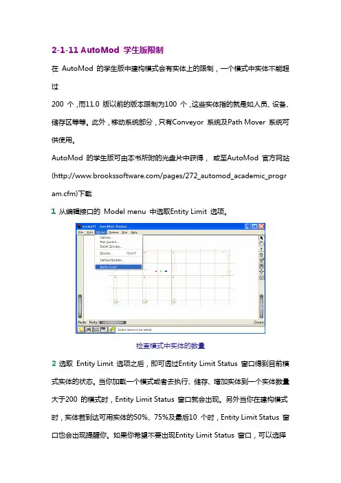
2-1-11 AutoMod 学生版限制在 AutoMod 的学生版中建构模式会有实体上的限制,一个模式中实体不能超过200 个,而11.0 版以前的版本限制为100 个,这些实体指的就是如人员、设备、储存区等等。
此外,移动系统部分,只有Conveyor 系统及Path Mover 系统可供使用。
AutoMod 的学生版可由本书所附的光盘片中获得,或至AutoMod 官方网站(/pages/272_automod_academic_program.cfm)下载1 从编辑接口的 Model menu 中选取Entity Limit 选项。
检查模式中实体的数量2 选取 Entity Limit 选项之后,即可透过Entity Limit Status 窗口得到目前模式实体的状态。
当你加载一个模式或者去执行、储存、增加实体到一个实体数量大于200 的模式时,Entity Limit Status 窗口就会出现。
另外当你在建构模式时,实体若到达可用实体的50%、75%及最后10 个时,Entity Limit Status 窗口也会出现提醒你。
如果你希望不要出现Entity Limit Status 窗口,可以选择Disable Warnings 的选项来关闭它。
模式中实体限制状态除此之外,这些实体会根据其本身之特性,被分类于不同的系统,如输送带系统、搬运系统等等。
因此为了得到更详细的实体数据,可以选择Show Entity Allocation 的选项来得到相关信息。
实体分类2-1-12 AutoMod 学生版与专业版之切换在某些情况下,我们会有学生版与专业版之间切换的需求,譬如:原先已安装了学生版,但因为已购买专业版而想改成专业版因教学需要,专业版数目不足而需改为学生版要将网络Server 专业版改为单机专业版要将单机专业版改为网络Server专业版我们可以不用重新安装而透过底下所介绍的小技巧来达成。

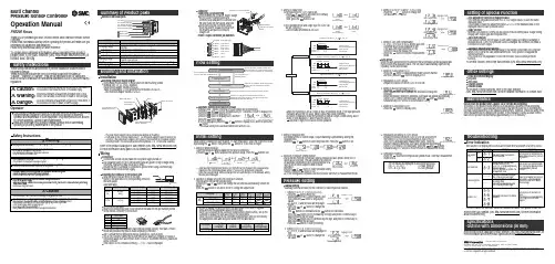
•Press the button to display [A1L].pressure.(When OUT1 setting is not necessary, press the and buttonsbutton to display [AP2].5, Preparation and setting of OUT2 device•Prepare the sensor for which OUT2 is to be set, and perform the setting of OUT2 in the same manner as that for OUT1.•After [A2L] is displayed and measurement starts, when thebuttons button and complete auto-preset mode. After that, measurement The set values are displayed in auto-preset as follows.ON = A - (A - B)/4 A = Max. pressure OFF = B + (A - B)/4B = Min. pressureFine adjustment function of displayed valueThis removes irregularities between CH1 to CH4 output values, to allow the same displayed value.It is possible to make fine adjustment within ±5%F.S. of the measured data on the displayed value for each pressure sensor.Copy functionWith the Copy function, 5 items can be copied, Pressure setting value, Range setting,Display unit, Output type and Response time.Auto-shift functionThis function corrects the set value of each switch output according to a change of pressure source. Even if the pressure source is changed, the controller can make a correction on switch output.Automatic identification functionThis function identifies the pressure range of the sensor connected to the controller.When [Aon] is set at the Auto identification mode, when power is re-applied this function activates.(This function is only applicable for use with the SMC PSE530 series pressure sensors).To set this function, refer to the SMC website (URL )Other SettingsPeak / Bottom hold display Key lock Zero clearChannel selects Channel scansTo set each of these functions, refer to the SMC website(URL ) for more detailed information, or contact SMC.MaintenanceHow to reset the product after a power cut or forcible de-energizingThe setting of the product will be retained as it was before a power cut or de-energizing.The output condition is also basically recovered to that before power cut or de-energizing,but may change depending on the operating environment. Therefore, check the safety of the whole installation before operating the product. If the installation is using accurate control,wait until the product has warmed up (approximately 20 to 30 minutes).TroubleshootingError IndicationThis function is to display error location and content when a problem or an error occurs.Note: Specifications are subject to change without prior notice and any obligation on the part of the manufacturer.© 2011 SMC Corporation All Rights ReservedAkihabara UDX 15F, 4-14-1, Sotokanda, Chiyoda-ku, Tokyo 101-0021, JAPAN Phone: +81 3-5207-8249 Fax: +81 3-5298-5362URL Auto-presetWhen the auto-preset function is selected, the set pressure can be calculated and memorized from a measured value. The set value is automatically optimized by repeating suction and release.button to display [AP1].2, Preparation of OUT1 device•Prepare the sensor for which OUT1 is to be set.button to change the4, Setting of Auto-shift compensation•[C_5] ([C_3] for CH2 to CH4) and the auto-shift corrected value will be displayed in turn.If the auto-shift input function is off, the button to return to measurement mode.SpecificationsOutline with Dimensions (in mm)Refer to the product catalogue or SMC website (URL ) for more information about the product specifications and outline dimensions.Refer to the SMC website (URL ) for more information about troubleshooting.5, Selection of pressure setting method•There are two methods for pressure setting: manual and auto-preset, either one of which can be selected. The auto-preset is provided for an automatic optimum set-up by using a sample for a case in which switch output is used to checkbutton to set.ConnectorConnecting / Disconnectinginto the socket, holding the lever andconnector body, and push the connector until the lever hooks into the housing, and locks. When removing the connector, press down the lever to release the hook from the housing and pull the connector straight out.Multi ChannelPressure Sensor ControllerOperation ManualPSE200 SeriesSafety InstructionsInstallationMounting with panel mount adapterFix the panel mount adapter to the product with the mounting screws (nominal size: 3 x 8 L, 2 pcs.) supplied.•Panel mount adapter (Model: ZS-26-B)Panel mount adapter + Front protective cover (Model: ZS-26-01)□48 conversion adapter (Model: ZS-26-D)Mounting and InstallationNames of individual partsThank you for purchasing an SMC PSE200 Series Multi Channel Pressure Sensor Controller.Please read this manual carefully before operating the product and make sure you understand its capabilities and limitations.Please keep this manual handy for future reference.To obtain more detailed information about operating this product,please refer to the SMC website (URL ) or contact SMC directly.These safety instructions are intended to prevent hazardous situations and/or equipment damage.These instructions indicate the level of potential hazard with the labels of"Caution", " Warning" or "Danger". They are all important notes for safety and must be followed in addition to International standards (ISO/IEC) and other safety regulations.OperatorPin No.3, Setting of output stylebutton and select the normally button to set.2)The operating mode and output style for OUT2 can be set. (only CH1)•Use the same procedure as for OUT1.4, Setting of response time•Set response time of switch output. Output chattering is prevented by setting the button to set.mode[Default setting]mode[Default setting]Flow SettingManual settingManually select a set value for the controller for each respective channel.button during the button to display set values.•[P_1] or [n_1] and set value are displayedin turn.button to change the button is to decrease.button once to decrease by one digit, and press it continuously to button to finish the setting.Pressure Setting(Model: ZS-26-01)Power / Output connector pin numbersAutomatic identification function releasebutton to display [SH1], and then button to display [AoF], and then press thebutton.Selection of Pressure range, Output style, Response time and Pressure setting method.Detects pressure, displays values and performs switching. Other functions such as zero clear can also be set if necessary.button for 2 seconds or longer.1, Setting of pressure rangebutton to set.( )101 kPa-101 kPa [Default setting]101 kPa1 MPa(Only PSE530 series)(Other than PSE530 series)2, Selection of display unit (with unit conversion function)button will change the unit and will automatically convert set values.button to set and to move to setting the output mode.∗: When automatic identification mode is ON, the controller will change to the pressure rangerequired for the connected pressure sensor (PSE530 only) when power is supplied.∗: When the pressure range setting is changed, the set value changes, so the pressure settingmust be performed again.[Default setting]Hysteresis mode (P_1, P_3 P_2, P_4)•When the hysteresis is set at 2 digits or less in hysteresis mode, if the input pressure fluctuates around the set value, switch output may cause chattering.•In window comparator mode the hysteresis is fixed at 3 digits. When setting, allow 7digits or more between P1 and P2 (and P3 and P4).2, Setting of OUT1 [P_2] (for CH1 to CH4)•[P_2] or [n_2] and set value are displayed in turn.button to change the Initial Settingmode[Default setting]mode∗: The panel mount adapter can be rotated by 90 degrees for mounting.∗: Front panel of this Controller meets IP65 (if 48 conversion adapter is used, it meets IP40). However, if the panel mount adapter is not secure or the instrument is not seated correctly,water might enter. The screws should be further tightened 1/4 to 1/2 turns after assembly.Attaching the connector to the sensor wire Strip the sensor wire as shown to the right.(Refer to the table below for corresponding connector and wire gauge).WiringConnectionConnections should only be made with the power supply turned off.Use separate routes for the controller wiring and any power or high voltage wiring.Otherwise, malfunction may result due to noise.Ensure that the FG terminal is connected to ground when using a commercially available switch-mode power supply.Check that the above preparation has been performed correctly, then part A shown should be pressed in by hand to make temporary connection.Part A should then be pressed in using a suitable tool, such as pliers.The e-con connector cannot be re-used once it has been fully crimped. In cases of connection failure such as incorrect order of wires or incomplete insertion, please use a new connector.If the sensor is not connected correctly, [----] or [---] will be displayed.Do not cut the insulator.Insert the corresponding wire colour shown in the table into the pin number printed on the sensor connector, to the bottom.Refer to the product catalogue or SMC website (URL )for more information about panel cut-out dimensions.。


AutoMod基本操作與簡介這一章的內容主要分成三個部分,第一節AutoMod基本操作主要是讓初學者能儘快地熟悉AutoMod軟體的操作環境,包括如何去開啟一個模式、建構一個模式等等,第二節AutoMod基本架構主要是讓使用者了解各系統模組的功能及特性,第三節AutoMod基本概念則是建立使用者在使用AutoMod建構模式時應該了解的基本概念。
2-2第一節 AutoMod 基本操作在本節中我們將針對AutoMod 的基本操作進行初步的介紹,包括如何開啟AutoMod 的介面、如何開啟一個模式、如何儲存一個模式,以及如何執行一個模式等相關的操作。
學習任何一套軟體的使用,初學者必須身體力行,花時間努力的研究並且實際去動手體驗,才是學習好軟體的不二法門。
學習AutoMod 當然也不例外,因此讀者若願意多花些時間研讀本書的內容,並且遵循書中的內容多做練習,相信即可以透過AutoMod 建構出有效的模式。
在安裝AutoMod 時,可選擇Standard(標準)模式或VR(虛擬實境)模式,其中本書的範例是以AutoMod 安裝在C 磁碟機及VR 模式呈現,所有範例皆可在AutoMod 11.0以上的版本實際練習與操作。
2-1-1 AutoMod 環境在整個AutoMod 軟體中,主要可分成兩個環境,編輯環境及模擬環境,其中: 編輯環境:提供使用者建構模式的環境及各項參數的設定。
模擬環境:可利用模擬環境進行模擬以獲得相關的統計資料,並將模式以動畫的方式呈現。
2-1-2 開啟AutoMod當你順利完成AutoMod 的安裝後,在程式集中點選AutoMod 12.0 (VR Graphics)中的AutoMod 選項即可打開AutoMod 的編輯介面。
這個編輯介面就是建構模式及定義模式相關參數的環境。
AutoMod 編輯介面AutoMod 基本操作與簡介2-32-1-3 建構模式要在AutoMod 的編輯介面中建構一個模式,你可以選擇建構一個新的模式或是開啟舊模式進行編輯。