三星exynos安卓androidpos机方案p讲义ptv
- 格式:ppt
- 大小:2.14 MB
- 文档页数:83

POSP系统技术方案书二零一六年四月目录1.前言 (4)1.1概述..........................................................................................................错误!未定义书签。
2.系统目标 (4)2.1系统需求 (4)2.2系统目标 (5)3.系统结构设计 (6)3.1系统建设原则 (6)3.2系统网络拓扑图 (8)3.3体系结构 (9)3.4交易处理流程 (10)3.4.1非账务类POS交易流程 (10)3.4.2账务类POS交易流程 (10)3.4.3管理类交易流程 (11)3.5软件体系架构 (11)4.接入服务系统 (13)5.应用系统 (13)5.1交易核心控制 (13)5.2应用路由选择 (14)5.3自动事务冲正 (14)6.交易监控系统 (15)6.1交易监控 (15)6.2状态监控 (15)7.前置机管理系统 (15)7.1操作员管理 (16)7.2设备管理 (16)7.3流水管理 (16)7.4业务管理 (16)7.5卡种管理 (16)7.6POS操作员管理 (17)7.7密钥管理 (17)7.8交易参数配置 (17)7.9报表管理 (17)8.安全系统设计 (19)8.1硬件加密 (19)8.2密钥体系 (19)8.2.1硬件加密机密钥结构 (20)8.2.2加密机密钥分类 (21)8.3前置系统安全解决方案 (22)8.3.1通讯数据加密 (22)8.3.2POS密钥处理 (23)9.系统出错处理 (25)10技术优势 (25)1.系统目标2.1系统需求系统安全性要求高,便于全行执行统一的安全策略,降低安全成本,提高安全水平 软件的模块化易于维护,业务便于拓展;系统能平滑过渡至银联卡业务;便于联接各种型号POS;开放性和扩展性强;避免网络系统建设与应用系统开发简单重复等现象;支持多种通讯方式(有线、无线等)。

三星电子VT-WINII培训教材(中文版)中文版目次CHIP件系列的检查原理自动抽出 (2)焊盘部 (3)三极管系列的检查原理自动抽出 (9)焊盘部 (10)IC系列的检查原理自动抽出 (14)焊盘部 (17)插座(从IC系列检查原理变更)自动抽出 (23)插入式元件自动抽出 (24)焊盘部 (24)基准校正的检查原理校正 (27)色参数的设定方法 (28)共通连接 (29)CHIP 件系列原理(电容/二极管/排电阻)注意:色参数设定时尽可能不要把白色的印迹和电路板面等对检查有影响的颜色設定进来。
□焊盘部的抽出□ 元件本体抽出□ 電極抽出□ 元件本体扩张功能上_(画素)下_(画素)① 进行焊盘部抽出时,焊盘窗口首先向实际的焊盘相对应的位置移動。
所有窗口也随之一起移动。
② 元件本体抽出或者電極抽出时,元件本体窗口向实际的本体位置移動。
扩大扩大象电容等元件先端有電極的元件适用于这一功能。
部品本体抽出後、沿窗口的箭头方向元件本体扩张。
扩张后的大小作为元件的本体尺寸。
注意:如果抽出比较安定,色参数的設定不受窗口外颜色的影响。
□ 缺件判定(焊锡形状)焊盘中央部元件漏贴时,焊盘中央部显示红色。
色参数...抽出焊锡的红色部分面積(%)_≧□ NG 的良品进行补救参数...抽出焊锡的兰色部分面積(%)_≧把検査領域的面積作为100%色参数設定的颜色如果抽出設定値以上 NG50% 把検査領域的面積作为100%良品良品焊锡量多的时候、焊锡如图所示,中央显示红色。
焊盘中央部的検査只通过面積設定,不能够分辨,判定为NG这样良品被判定不良。
为避免这样的误判断,这种形状的焊锡,利用焊盘元件側检查,对良品进行补救。
□ 電極有無...用于焊锡量過多的検出。
電極上如果粘上焊锡電極的面積就会減少。
色参数...抽出電極的红色面積_(%)≧□ 横向偏移_(%)通过自動抽出窗口中抽出的焊盘和元件位置进行判定。
色参数不必設定。
□ 纵向偏移_(%)通过自動抽出窗口中抽出的焊盘和元件位置进行判定。
Samsung Exynos 4 Quad(Exynos 4412)RISC MicroprocessorRevision 1.00October 2012 U s e r's M a n u a l2012 Samsung Electronics Co., Ltd. All rights reserved.Important NoticeSamsung Electronics Co. Ltd. (“Samsung”) reserves the right to make changes to the information in this publication at any time without prior notice. All information provided is for reference purpose only. Samsung assumes no responsibility for possible errors or omissions, or for any consequences resulting from the use of the information contained herein.This publication on its own does not convey any license, either express or implied, relating to any Samsung and/or third-party products, under the intellectual property rights of Samsung and/or any third parties.Samsung makes no warranty, representation, or guarantee regarding the suitability of its products for any particular purpose, nor does Samsung assume any liability arising out of the application or use of any product or circuit and specifically disclaims any and all liability, including without limitation any consequential or incidental damages.Customers are responsible for their own products and applications. "Typical" parameters can and do vary in different applications. All operating parameters, including "Typicals" must be validated for each customer application by the customer's technical experts.Samsung products are not designed, intended, or authorized for use in applications intended to support or sustain life, or for any other application in which the failure of the Samsung product could reasonably be expected to create a situation where personal injury or death may occur. Customers acknowledge and agree that they are solely responsible to meet all other legal and regulatory requirements regarding their applications using Samsung products notwithstanding any information provided in this publication. Customer shall indemnify and hold Samsung and its officers, employees, subsidiaries, affiliates, and distributors harmless against all claims, costs, damages, expenses, and reasonable attorney fees arising out of, either directly or indirectly, any claim (including but not limited to personal injury or death) thatmay be associated with such unintended, unauthorizedand/or illegal use.WARNING No part of this publication may be reproduced, stored in a retrieval system, or transmitted in any form or by any means, electric or mechanical, by photocopying, recording, or otherwise, without the prior written consent of Samsung. This publication is intended for use by designated recipients only. This publication contains confidential information (including trade secrets) of Samsung protectedby Competition Law, Trade Secrets Protection Act and other related laws, and therefore may not be, in part or in whole, directly or indirectly publicized, distributed, photocopied or used (including in a posting on the Internet where unspecified access is possible) by any unauthorized third party. Samsung reserves its right to take any and all measures both in equity and law available to it and claim full damages against any party that misappropriates Samsung’s trade secrets and/or confidential information.警告本文件仅向经韩国三星电子株式会社授权的人员提供,其内容含有商业秘密保护相关法规规定并受其保护的三星电子株式会社商业秘密,任何直接或间接非法向第三人披露、传播、复制或允许第三人使用该文件全部或部分内容的行为(包括在互联网等公开媒介刊登该商业秘密而可能导致不特定第三人获取相关信息的行为)皆为法律严格禁止。
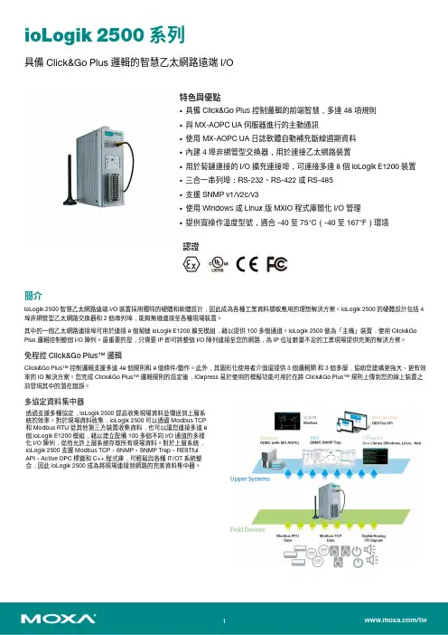
ioLogik2500系列具備Click&Go Plus邏輯的智慧乙太網路遠端I/O特色與優點•具備Click&Go Plus控制邏輯的前端智慧,多達48項規則•與MX-AOPC UA伺服器進行的主動通訊•使用MX-AOPC UA日誌軟體自動補充斷線週期資料•內建4埠非網管型交換器,用於連接乙太網路裝置•用於菊鏈連接的I/O擴充連接埠,可連接多達8個ioLogik E1200裝置•三合一串列埠:RS-232、RS-422或RS-485•支援SNMP v1/v2c/v3•使用Windows或Linux版MXIO程式庫簡化I/O管理•提供寬操作溫度型號,適合-40至75°C(-40至167°F)環境認證簡介ioLogik2500智慧乙太網路遠端I/O裝置採用獨特的硬體和軟體設計,因此成為各種工業資料擷取應用的理想解決方案。
ioLogik2500的硬體設計包括4埠非網管型乙太網路交換器和2個串列埠,能夠無縫連接至各種現場裝置。
其中的一個乙太網路連接埠可用於連接8個菊鏈ioLogik E1200擴充模組,藉以提供100多個通道。
ioLogik2500做為「主機」裝置,使用Click&Go Plus邏輯控制整個I/O陣列。
最重要的是,只需要IP即可將整個I/O陣列連接至您的網路,為IP位址數量不足的工業現場提供完美的解決方案。
免程控Click&Go Plus™邏輯Click&Go Plus™控制邏輯支援多達48個規則和8個條件/動作。
此外,其圖形化使用者介面還提供3個邏輯閘和3個多層,協助您建構更強大、更有效率的IO解決方案。
您完成Click&Go Plus™邏輯規則的設定後,IOxpress易於使用的模擬功能可用於在將Click&Go Plus™規則上傳到您的線上裝置之前發現其中的潛在錯誤。
多協定資料集中器透過支援多種協定,ioLogik2500提高收集現場資料並傳送到上層系統的效率。

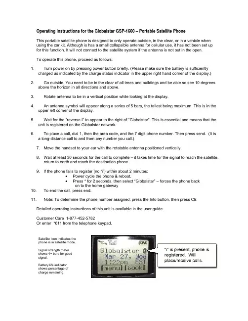
Operating Instructions for the Globalstar GSP-1600 – Portable Satellite PhoneThis portable satellite phone is designed to only operate outside, in the clear, or in a vehicle when using the car kit. Although is has a small collapsible antenna for cellular use, it has not been set up for this function. It will not connect to the satellite system if the antenna is not out in the open.To operate this phone, proceed as follows:1. Turn power on by pressing power button briefly. (Please make sure the battery is sufficientlycharged as indicated by the charge status indicator in the upper right hand corner of the display.) 2. Go outside. You need to be in the clear of all trees and buildings and be able so see 10 degreesabove the horizon in all directions and above.3. Rotate antenna to be in a vertical position while looking at the display.4. An antenna symbol will appear along a series of 5 bars, the tallest being maximum. This is in theupper left corner of the display.5. Wait for the "reverse I" to appear to the right of "Globalstar". This is essential and means that theunit is registered on the Globalstar network.6. To place a call, dial 1, then the area code, and the 7 digit phone number. Then press send. (It isa long-distance call to and from any number you call.)7. Move the handset to your ear with the rotatable antenna positioned vertically.8. Wait at least 30 seconds for the call to complete – it takes time for the signal to reach the satellite,return to earth and reach the destination phone.9. If the phone fails to register (no “i”) within about 2 minutes:•Power cycle the phone & reboot.•Press * for 2 seconds, then select “Globalstar” – forces the phone backon to the home gateway10. To end the call, press end.11. Note: To determine the phone number assigned, press the Info button, then press Clr.Detailed operating instructions of this unit is available in the user guide.Customer Care 1-877-452-5782Or enter *611 from the telephone keypad.Satellite Icon indicates thephone is in satellite mode.Signal strength metershows 4+ bars for goodsignal.Battery life indicatorshows percentage ofcharge remaining.GSP 1600 portable satellite phoneWith the addition of a Car-kit:Operating the portable satellite phone from a vehicle is identical, EXCEPT, that you must place the portable magnetic-mount antenna on the metal roof of the car. The vehicle must be away from trees, buildings, etc, so that the antenna has a clear view of the sky. The phone may be charged with the optional cigarette-lighter accessory while in the vehicle, so as not to run down the phone battery. Read the instruction sheets for installing in a vehicle.Operating Instructions for the Globalstar GSP-2900 “Fixed” satellite phoneThis fixed site satellite phone is designed for in-building use and interfaces with a standard analog telephone set for control of all its functions.1. To place a call, lift the handset and confirm there is dial tone. Dial the number by dialing 1, areacode and the seven digit phone number. (It is a long-distance call to and from any number you call.)•Do NOT dial a 9 before the 1+ 10-digit number, unless your phone is wired into your PBX (switchboard) This will result in a call failure.•DO dial the 1 +area code+ seven-digit number.2. Wait at least 30 seconds for the call to connect to the satellite and back down to the destinationphone number. This is called latency – it takes longer than a cell phone or land-line phone to connect.3. If you get a fast-busy signal, this usually indicates that there is no satellite within range of theantenna. Hang up and wait 2-3 minutes. Try your call again.4. If you need assistance, have questions, or want to report a problem, call the Customer Careservice desk at the number below, or contact the installation vendor that installed your phone. Customer Care 1-877-452-5782Or enter *611 from the telephone keypad.Roof-top antenna。


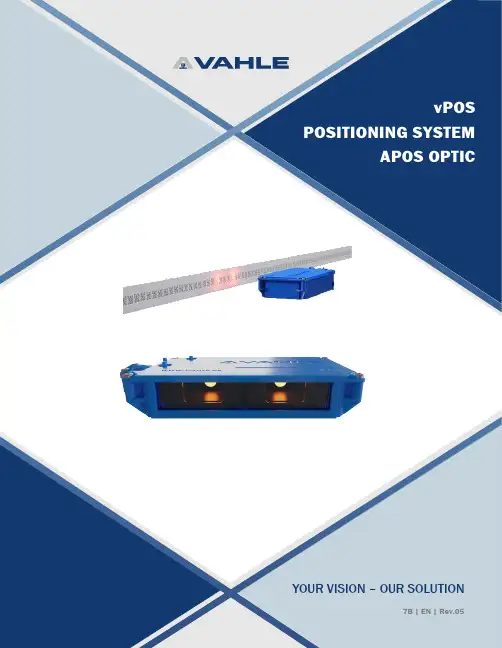
YOUR VISION – OUR SOLUTION7B | EN | Rev.052APOS OPTIC – KEY HIGHLIGHTSRELIABLE POSITIONING SYSTEMDual integrated cameras ensure high reliability in critical functions. Instant and accurate positioning is available after system interruptions or restarts.COMPLETE SOLUTIONSAPOS Optic offers simple and easy assembly and integration with other VAHLE systems to provide compact and efficient solutions in one pack -age.SAFE POSITIONFor safety-related applications a security function referred to as “Safe Position” with Performance Level d, Cat. 3, in accordance with DIN EN ISO 13849-1, can be realised in conjunction with TÜV-certified TIA sys -tem modules.QUICK COMMISSIONING AND MAINTENANCEWith the help of the APOS Optic Diagnosis Kit and the APOS ServiceTool software the data of the reading heads can be read, updates can be carried out, the code strip inspected and errors of the reading head canbe analysed.Fail-safe SPSPROFINETAPOS OPTIC PROFINET APOS OPTIC PROFINETET200SP-F CPU1510SP-FVAHLE TIA FBfor safe positioning3 APOS OPTIC – FUNCTIONModern material handling applications such as automobile production, assembly lines and storage and retrieval systems require gapless and exact positioning of the mobile equipment throughout the entire processing cycle. APOS Optic - of the product range vPOS - achieves this task by providing optical reading of the DataMatrix code strip.OPERATIONVAHLE APOS Optic reading heads come equipped with dual cameras and integrated LED lighting. The dual cameras allow the reading head to detect up to six DataMatrix code fields at one time. Only one code field is required to determine positioning. This redundancy allows the reading head to bride small gaps or damages to the codetape without error. The integrated LED lighting is another factor that ensures process reliable detection.The positioning systems operates with the simple and efficient Data Matrix code strip. This permits absolute position detection up to a maximum trav-4*More protocol types are available on request. Please contact our Techsales in case of need.APOS OPTIC – SERIAL READING HEADSTECHNICAL DATAELECTRICAL DATAVoltage ....................................24 VDC (20 … 30 VDC)Power consumption ...............Max. 130 mA Power input .............................<3 W Start-up time ..........................<2 secMEASUREMENT ELECTRONICSAccuracy ..................................±1 mmReading rate ...........................≤3 m/s (180 m/min)Lighting ...................................Integrated LED code strip lightingM-12 CONNECTIONSPlug coding ............................. 4-pole A-coded (RS485)8-pole A-coded (SSI)AMBIENT CONDITIONSOperating temperature ..........0°C ... 60°CStorage temperature ..............−15°C ... 60°CMECHANICAL DATAProtection Type .......................IP54Depth of field ..........................±14 mm Inclination ...............................±1.5°Dimensions .............................155 x 64 x 27 mm Weight .....................................approx. 200 g Tolerances height ...................4 mm / 6 mmReading distance ...................29 or 36 mm (see below)DIMENSIONSRANGE OF PRODUCTS64 m m27 m m 155 mmDescriptionProtocol*Data Rate [kBit/s]Order No.Reading distance O3: 29 mm LK-O3-RS485-D-576-D1-54DETO57.610011578Reading distance O2: 36 mm LK-O2-RS485-D-576-D1-54DETO57.610004140LK-O2-RS485-S-625-D1-54Binary protocol type 262.510005457LK-O2-RS485-S-576-D1-54Binary protocol type 257.610005456LK-O2-SSI-4-D1-54SSI GRAY PST (SEW)-10014882LK-02-RS485-D-576-DX-54DETO57.610013786LK-O2-SSI-2-D1-54Binary protocol-10013467LK-O2-SSI-3-D1-54SSI GRAY PRE (Siemens)-100220065APOS OPTIC – PROFINET READING HEADSTECHNICAL DATAELECTRICAL DATAVoltage ....................................24 VDC (20 … 30 VDC)Power consumption ...............Max. 600 mA Power input .............................<13 W Start-up time ..........................<2 secMEASUREMENT ELECTRONICSAccuracy ..................................±1 mmReading rate ...........................≤3 m/s (180 m/min)Lighting ...................................Integrated LED code strip lightingM-12 CONNECTIONSPlug coding .............................4-pole A-coded4-pole D-codedAMBIENT CONDITIONSOperating temperature ..........0°C ... 60°CStorage temperature ..............−15°C ... 60°CMECHANICAL DATAProtection Type .......................IP54Depth of field ..........................±14 mm Inclination ...............................±1.5°Dimensions .............................155 x 64 x 50 mm Weight .....................................approx. 260 g Tolerances height ...................4 mm / 6 mm Reading distance ...................36 mmDIMENSIONSRANGE OF PRODUCTSStandard versionPROFISAFE version6*More code strip lengths are available on request. Please contact our Techsales in case of need.APOS OPTIC – DIAGNOSISAPOS OPTIC – DATA MATRIX CODE STRIPAPOS OPTIC DIAGNOSIS KITThe APOS Optic Diagnosis Kit enables a complete diagnosis and trouble shooting.The APOS optic ServiceTool allows for:• Firmware updates and restarting the reading heads• Display of the current position values of each camera• Graphic presentation of the position progression• Display of camera imagesWith the help of the APOS Code Generator, defective code strip segments can quickly be reprinted and replaced.Please contact our Techsales in case of need.RANGE OF PRODUCTSRANGE OF PRODUCTSDescription Order No. APOS Optic Diagnosis Kit Diagnosis interface, PC APOS optic Service Tool-Lite, APOS optic Code Generator USB/RS485 adapter, USB/RS422 adapter, power adapter and case10014747Description Coding Order No. Code strip : 100 m drum*Code Strip CB250 – 100.00010004169 Code Strip CB25100.001 – 200.00010005781 Code Strip CB25200.001 – 300.00010005782 Code Strip CB25300.001 – 400.00010005784 Code Strip CB25400.001 – 500.00010005786 Code strip : 50 m drum*Code Strip CB250 – 50.00010010849 Code Strip CB25100.001 – 150.00010012051 Code Strip CB25200.001 – 250.000100126107APOS OPTIC – FIXING MATERIALAPOS OPTIC – SYSTEM INTEGRATIONRANGE OF PRODUCTSDescriptionDimensions Order No.Support profile for data matrix code strip VTS-TP-28 x 2 x 6000-S 28 x 2 x 6000 mm P9999996(1)Universal bracket for reading headVTS-HLK-SHE-SB71.5 x 3 x 120 mm0144509EXAMPLE: EMS APPLICATION (2)1 T he APOS Optic code strip is mounted in the EMS profilePAUL VAHLE GmbH & Co. KGWesticker Str. 5259174 Kamen Germany Phone: +49 2307 704-0*************VAHLE Incorporated 407 Cane Island Pkwy Katy, TX, 77494, USA Phone: +1 713-465-9796 ******************connect with us! @vahleincW 2516631/00/e n | 0 | R e v .05 | 06/20 | E r r o r s a n d t e c h n i c a l m o d i f i c a t i o n s s u b j e c t t o c h a n g e .。
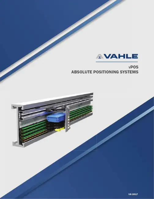
US 2017V POSABSOLUTE POSITIONING SYSTEMSV POS POSITIONING SYSTEMS INTELLIGENT SOLUTIONS FOR INDUSTRY 4.0Developed initially for automated material handling systems, VAHLE vPOS positioning systems allow the control system to constantly monitor the absolute position of the mobile system components. All VAHLE vPOS systems can be easily integrated with most VAHLE conductor bar & data transfer products to provide a compact solution for various automated applications. VAHLE positioning systems may also be installed independently allowing for complete installation fl exibility.V POS SYSTEM TYPESAPOS MAGNETIC - uses a code strip with magnetic coding and sliding reading head to supplypositioning to the control system.APOS CONTACTLESS - uses a code strip with magnetic coding and a contactless reading head tosupply positioning to the control system.APOS OPTIC - uses a data matrix and dual camera optical reading head to supply positioning to thecontrol system.TypeAPOS MagneticAPOS ContactlessAPOS OpticSystem Length (1)515 meters 260 meters 10,000 meters Travel Speed Up to 12 m/s Up to 6 m/s Up to 3 m/s Resolution 1 mm 1 mm 1 mm Power Supply 8 - 26 VDC 10 - 30VDC 20 - 30 VDC Temperature Range - 14°C - 55° C 0 - 50°C 0 - 60°C Protective SystemIP 54 IP 50, 64 IP 54Min. Horizontal Curve Radius 750 mm 2500 mm 750 mm Min. Vertical Curve Radius 2300 mm Consult factory 2300 mm Internal Light SourceN/AN/ADual LEDOVERVIEW SPECIFICATIONS(1) Longer lengths possible. Contact VAHLE directly for details3 SYSTEM ADVANTAGES• A bsolute position determination up to 515 m• I ntegration with conductor bar systems for space saving solutions orindependently parallel to the vehicle track• R etrofits to existing systems• Absolute position immediately available when switching on or after apower failure• Travel speed up to 12 m/s• R esistant to environmental conditions such as dust or humidity• U naffected by lighting conditions• O ptical version available - see page 6COMPONENTS - APOS MAGNETIC & CONTACTLESSThe code strip comes factory assembled with asequential and specifi c cross-magnetized code.Max continuous strip length is 262 meters.The code rail consists of the support profi le (1),the code strip (2), and the sliding strip (3). Thesliding strip prevents code strip wear and providesguidance for the APOS LKG-17 reading head.Sliding scanner for APOS magnetic systems.Simple integration with U 10 and VKS 10 collectorassemblies.Contactless scanning for enclosed powerailsystems KBH and MKH.Logging of APOS to CANopen, Profi bus DP andothers.Guide carrier for the mounting of the LBcontactless reading head for KBH and MKHenclosed powerail systems.Code strip Code rail LKG-17 reading head LB-15 reading head SU interface moduleReading head carrier LWOPERATION - APOS MAGNETIC & CONTACTLESS123VAHLE APOS Magnetic & Contactless consist of a code strip with magneticcoding and a reading head with integrated electronics, which transmitsthe position to the control system interface. The intelligent readinghead determines the position from the code strip and transmits it todownstream control systems for processing.Type Details Interface U 10VKS 10Order-no.10-pole11-poleCode StripCB 808.0 mm; max. coil length 262 m-•••2823255Support Profi lesTPA U10 6 meter -•2823258TPA U10 4 meter -•2823468TPA VKS 10/1010th Pole -•2823259TPA VKS 10/1111th Pole -•2823265Support Profi le AccessoriesUV 10A Profi le Joint -•2823267USK 10A Fixpoint -•2823268US 10A Transfer Guide -•2823270US 10A-D Transfer Guide -•2823609UDV 10A-30M Expansion Joint -•2823269Adhesive Tape Code Strip Fixpoint -•2823028VK 10A Joint Cover - 11th Pole -•2823444VEPS 10-CACode Strip Fixpoint -••2823283Glide StripGB 80Guidance & protection -•••2823446Reading Heads (1)LLG-C 17Single Arm (Long)SSI •••2823696LLG-C 17Single Arm (Long)RS 485••• 2823693LKG-A 17 Single Arm (Short)SSI •••2823681LKG-A 17Single Arm (Short)RS 485•••2823626Interface ModuleSU-CAN--•••2823262SU-Profi bius (LKG, LLG)--•••2518699SU-Interbus--•••2823264ORDER NUMBERSAPOS - MAGNETICIntegrates with VAHLE unipole and multi-enclosed conductor bar systems. APOS U10 version also available as stand alone system.U 1010-pole 11-poleVKS 10(1) Additional versions available. Contact VAHLE directly for details.5 ORDER NUMBERSAPOS - CONTACTLESSIntegrates with VAHLE enclosed conductor bar systems. KBH & MKH versions can be installed as standalone systems without conductor usage. Additional integration with VAHLE vCOM data transmission systems possible.(1)KBHMKHType Details Interface KBH MKH Order-no. Code StripCB 757.5mm-••2823254 Fixing Profi leFP 20 Fixing Profi le-•2823280 FP 25Fixing Profi le-•2823257 Contactless Reading HeadLB 15 Standard-Schutz RS 485••2823159 LB 15 Standard-Schutz SSI Gray Code••2823252 LB 15 Standard-Schutz SSI Binary ••2823557 LB 15 IP54IP54-Schutz RS 485••2823555 LB 15 IP54IP54-Schutz SSI Gray Code ••2823554 Reading Head CarrierLWK Reading Head Carrier-•2823445 LWM Reading Head Carrier -•2823261 End TerminationZAK2x End Sections-•2823281 ZAM2x End Sections-•2823282 Threading ToolEZR 9/10Threading Tool-••234730 (1) Contact VAHLE directly for details and applications.SYSTEM ADVANTAGES• A bsolute position determination up to 10,000 meters total system length• C ontactless• C ompact design and reliable transmission by DataMatrix-code• A bsolute position immediately available when switching on or after a power failure • Simple and minimal installation• I ntegration into U10 collector assembly • U naffected by lighting conditions • A ble to bridge code gaps up to 40mmVAHLE APOS OPTIC consists of a dual camera reading head and DataMatrixcode strip installed directly onto the EMS or support profi le. Using the LEDilluminated dual cameras, 6 codes are read simultaneously (only 1 code isrequired) — offering position determination down to +/- 1mm. The compactread head integrates seamlessly into the standard U10 collector assemblyor a universal mounting plate, making installation simple and effi cient.OPERATION - APOS OPTICRead head version RS485SSI Profinet Electrical dataVoltage24VDC (20 … 30VDC)Power consumption Max. 130 mA Max. 250 mA Power input< 3 W< 13 WStart-up time< 2 sMeasurement electronicsAccuracy± 1 mmReading rate≤ 3 m/s (180 m/min)Lighting Integrated LED code strip lightingM12-connectionsPower supply 4 pole, A coded8 pole, A coded 4 pole, A coded DiagnosisCommunication 4 pole, D coded Ambient conditionsOperating temperature0°C - 60°C (32°F - 140°F)Storage temperature-15°C - 60°C (5°F - 140°F)Mechanical dataProtection type IP54Depth of field±14 mmTolerances± 1.5°Tolerances155 x 64 x 27 mm155 x 64 x 50 mm Weight approx. 200 g (7oz)approx. 260 g (9oz)Tolerances inclination 4 mm6 mm 4 mm6 mm4 mm6 mmTECHNICAL SPECIFICATIONSMounting boltPower supplyCommunicationDiagnosis Image camera 1Image camera 2Readingdistance*Detection of up to 6 code fi elds M12 plug* The reading distance of 29 mm is only applicable in conjunction with code strip carriers and assembly on the current collector package.read headcode tape7Optical reading head with dual cameras and LEDillumination. Able to read 6 codes simultaneouslyto bridge gaps & interruptions up to 40mm. Simpleinstallation in standard U10 collector bracket.Data matrix code strip with adhesive backingfor simple installation. Max continuous length of500 meters.Installation tool for quick & consistent attachmentof code strip to web of EMS profi le. Mounts directlyto specifi c EMS beams.DATA MATRIX CODE STRIP INSTALLATION TOOL SERIAL READING HEADCOMPONENTS - APOS OPTICPROFINET READING HEAD SUPPORT PROFILEQUICK COMMISSIONING AND MAINTENANCEUtilizing the APOS Optic diagnostic kit and service tool software, anyread head can be turned into a real time camera for visual inspectionof code band. Additionally, fi rmware updates can be implemented anddamaged sections of code band can be produced and printed for quickreplacement. See page 11 for details.UNIVERSAL JOINT MATERIALOptical reading head with dual cameras and LEDillumination. Able to read 6 codes simultaneouslyto bridge gaps & interruptions up to 40mm. Foruse with APOS Optic “Safe Position.”Optional backing for data matrix code strip.Supplied in 6 meter lengthsJoint material for optional support profi le.SAFE POSITIONFor safety related applications requiring additional security, VAHLE offersProfi net read heads. These read heads allow security function “SafePosition” to be realized in accordance with DIN EN ISO13849-1 whenused in conjunction with TUV-certifi ed TIA system modulesORDER NUMBERS – SERIAL READ HEADSTo mobile control / SPSM12 – plug RS485: 4 pole SSI: 8 poleInterfaceProtocolData rate [kBit/s]Order No.Reading distance O2: 36 mm LK-O2-RS485-D-1152-D1-54DETO 115.210010601LK-O2-RS485-D-625-D1-54DETO 62.510004141LK-O2-RS485-D-576-D1-54DETO57.610004140LK-O2-RS485-S-625-D1-54Binärprotokoll Typ 262.510005457LK-O2-RS485-S-576-D1-54Binärprotokoll Typ 257.610005456LK-O2-SSI-4-D1-5425Bit GRAY-10014882Reading distance O3: 29 mm LK-O3-RS485-D-576-D1-54DETO 57.610011578DIMENSIONS PROTOCOLS500m m64m m27m m155mmMounting options for read head:• on the collector plate• on universal mounting plateRS485 - DETO PROTOCOL (data format: 8n1)RS485 - Binary protocol Type 2 (data format: 9n1)SSI - 25Bit GRAY Protocol (Request via CLK)RepetitionRequestRequestResponseResponse9ORDER NUMBERS– PROFINET READ HEADSM12 – s ockets2 x LANM12 – plug, 4 pole power supply diagnosisInterfaceProtocolData rate [MBit/s]Order No.Reading distance O2: 36 mm LK-O2-PNIO2-S-D1-54PROFINET-IO CC-B 10010011072LK-O2-PNIO2-SAFE-DX-54Incl. VAHLE TIA PROFINET component*PROFINET-IO CC-B10010013679DIMENSIONS APOS OPTIC PN SAFE POSITION* Always assemble two read heads (LK-O2-PNIO2-SAFE) for the APOS Optic System “Safe Position.“ With the SPS either use CPU 1510SP F-1 PN or CPU 1512SP F-1 PN (both Siemens, product family ET200-SP). The version Standard PROFINET only requires one read head (LK-O2-PNIO2-S).500m m64m m155mm50mmMounting options for read head:• on universal mounting plateVAHLE TIA FB for safe positioningError-safe SPSORDER NUMBERS –SUPPORT PROFILEDescriptionDimensionsOrder No.Support profile for CB VTS-TP-28x2x6000-S 28x2x6000 mm 0144286/00Universal joint material VTS-VM-28-S 28x2 mm 0144308/00Earthing cable complete for connection of support profileVTS-EL-RRKA-2,5-135-RK-S2,5 mm²0144312/00Universal joint materialORDER NUMBERS –DATA MATRIX CODE STRIP12mmYYYY-MM-DD0000.00 m CB-10X10 VAHLE powered by DETODescriptionCodingDimensionsOrder No.Code strip 100 m Coil Code strip CB250 - 100.00025x10x10 mm 10004169Code strip CB25100.001 - 200.00025x10x10 mm 10005781Code strip CB25200.001 - 300.00025x10x10 mm 10005782Code strip CB25300.001 - 400.00025x10x10 mm 10005884Code strip CB25400.001 - 500.00025x10x10 mm10005786Code strip 50 m Coil Code strip CB250 - 50.00025x10x10 mm 10010849Code strip CB25100.001 - 150.00025x10x10 mm 10012051Code strip CB25200.001 - 250.00025x10x10 mm1001261011 APOS OPTIC – DIAGNOSIS KITThe APOS Optic Diagnosis Kit enables complete system review and troubleshooting.The APOS Optic Service Tool allows for:• Firmware updates and rebooting the read heads• Display of the current position values of each camera• Graphic presentation of the position progression• Display of camera images for visual inspectionWith the help of the APOS Code Generator, defective code strip segments can quickly be reprinted and replaced.Description Scope of delivery Order No.APOS Optic Diagnostic Kit Diagnosis interfacePC APOS Optic Service Tool-LiteAPOS Optic Code Generator USB/RS485 adapterUSB/RS422 adapterpower adaptercase 10014747All APOS Optic typesEasy & quickdiagnosisServiceTool-Liteandcode generator**************************************,SPECIALOFFERS,ANDMORE!VAHLE Inc.1169 Brittmoore Rd.Houston, TX 77043Tel: 713-465-9796E-mail:***********************。
No matter where your remote jobsite is located,Globalstar is your trusted companion.The GSP-1600 delivers clear digital voice and data communications virtually anywhere, combining Code Division Multiple Access (CDMA) technology and a constellation of multiple Low-Earth Orbit (LEO) satellites.LEO satellites enable Globalstar to practically eliminate voice delay and maintain optimum battery life.The handset is also compact,which makes it easy to travel with.Plus it’s reliable, ensuring superior voice quality and fewer dropped calls.Like many Globalstar products,the GSP-1600 provides a reliable,low-cost data solution that ensures the ability to send information via email or the Internet virtually anywhere in the world.Globalstar T ri-Mode phones are designed with the flexibility to meet the needs of customers who already depend on wireless communications, but find themselves in areas where cellular or radio coverage is either unavailable or inaccessible. The Globalstar T ri-Mode phone is designed to complement existing fixed and cellular telephone networks by switching from terrestrial cellular telephony to satellite telephony asrequired. These features provide the Globalstar user the highest level of service and convenience.HANDHELD TRI-MODE PHONE ADVANTAGES:•Modes-Globalstar CDMA Satellite-Cellular Digital CDMA (800 MHz)-Cellular Analog AMPS (800 MHz)•Comfortable and lightweight design•Satellite antenna rotates and stows into the handset for convenience•Easy to use and portableA WIDE RANGE OF GLOBALSTAR SERVICES INCLUDE:•Voice•Voice Mail Services•Data Services•Short Message Service (SMS)•Display Position Location InformationDATA SERVICES:Through the GSP-1600, Globalstar offers efficient and reliable 9600 bps data services. Subscribers canaccess data services through the Globalstar network or through direct dial-up services from virtuallyanywhere in the world. Using the data cable to connect the T ri-Mode phone to a computer’s RS232 port, sending and receiving information has never been easier. The Globalstar Data Kit (not included)includes a software CD and cable for installation and use.GSP-1600 INCLUDES:•GSP-1600 Handset•Lithium Ion Battery•North American Wall Charger•User Manual•Optional Accessories (not included) – see reverseVisit Globalstar at www.globalstar.ca for service plan and coverage details.Some conditions apply.Rates for minutes based on individual price plan.Coverage may vary.Specifications subject to change without notice.Ask your local Globalstar Authorized Dealer for complete pricing and coverage information.Or see complete details at www.globalstar.ca.Globalstar Canada Satellite Co.© 2004.All rights reserved.75 Watline Avenue,Suite 140,Mississauga ON L4Z 3E5 Canada,P: 1.877.728.7466,F: 905.890.2175.Please see complete details of Globalstar service in the Terms and Conditions on our website,www.globalstar.ca.TECHNICAL SPECIFICATIONS GSP-1600 HANDHELD TRI-MODE PHONE TEMPERATURE RANGEPhoneCar Kit Antenna Car Kit CradleRF POWER OUTPUT (CAR KIT)OPERATIONAL-20 to +55ºC (-4 to +131ºF)-30 to +50ºC (-22 to +122ºF)-30 to +50ºC (-22 to +122ºF)NON-OPERATIONAL-30 to +60ºC (-22 to +140ºF)-40 to +85ºC (-40 to +185ºF)-40 to +85ºC (-40 to +185ºF)400 mW maximum (+26 dBm) (Satellite mode).89 watts maximum (+29.5 dBm)VOCODER 8k variable rate vocoder for Globalstar mode 13k variable rate vocoder for CDMA mode FREQUENCY RANGEGlobalstar T ransmit: 1610.73 to 1625.49 MHz Globalstar Receive: 2484.39 to 2499.15 MHzCellular T ransmit: 824.01 to 848.97 MHz Cellular Receive: 869.01 to 893.97 MHz TECHNOLOGYGlobalstar Satellite Mode (CDMA)800 MHz CDMA (Digital Cellular)800 MHz AMPS (Analog Cellular)TRI-MODE PHONE SIZE SPECIFICATIONS:*The Globalstar T ri-Mode phone offers an ergonomic design that makes it comfortable for hand-held operation. The phone measures 400cc in total volume and weighs 384 grams.The height is 177 mm, the width is 57 mm and the thickness is 48 mm (excluding the cellular antenna). The antenna, when held in a vertical position,communicates with the Globalstar satellite at elevations more than 10 degrees above the horizon. The Globalstar antenna rotates and stows into the handset for convenience when not in use.* All measurements for height and volume include standard battery and assume the Globalstar antenna is stowed.DATA CABLECIGARETTE LIGHTER ADAPTER/CHARGERUNIVERSAL TRAVEL CHARGERNORTH AMERICAN WALL CHARGERPROTECTIVE LEATHER CASELITHIUM ION BATTERY PACKHANDS-FREE CAR KITACCESSORIES (OPTIONAL)TALK TIME/STANDBY TIME:•In Globalstar satellite mode, the phone will sustain normal operation for 3.75 hours of talk time, 19 hours of standby time.•In CDMA (IS-95) mode, the phone will sustain normal operation for 4.7 hours of talk time or 75 hours of standby time.•In AMPS (IS-41) mode, the phone will sustain normal operation for 2.8 hours of talk time or 15 hours of standby time.FEATURES:•Battery Meter•Signal Strength Indicator •Voice Mail Notification •99 Memory location with call restriction •Call History Logwww.globalstar.ca。