MMW-1说明书
- 格式:doc
- 大小:296.00 KB
- 文档页数:10
MG200/500-WD1 MG200/530-WD1MG250/600-WD1 MG250/630-WD1型交流电牵引采煤机MG300/700-WD1 MG300/730-WD1产品使用维护说明书执行标准:MT/T 81-1998MT/T 82-1998MT/T 84-1997Q/XM 181-2008西安煤矿机械有限公司2010.10目录第一章安全手册 (1)1.设备使用维护说明书中的警示符号 (1)2.采煤机上的标志 (1)3.概述 (1)4.正确使用 (1)5.运输和安装 (2)6.工作人员 (2)7.操作、维护及修理 (3)8.环境保护 (4)9.其他危险 (4)第二章整机 (6)1.概述 (6)2.主要技术特征 (6)3.主要组成部分及工作原理: (13)4.结构特点: (14)第三章牵引机构 (16)1.概述 (16)2.牵引机构的机械传动 (16)2.1 牵引机构的传动系统 (16)2.2主要结构 (16)2.2.1电机齿轮轴 (19)2.2.3牵引轴 (20)2.2.4 中心齿轮组 (20)2.2.5行星减速器 (20)2.2.6行走机构 (22)3.牵引电机 (24)4.液压制动器 (25)4.1 工作原理: (25)4.2 机械释放(松闸) (26)4.3 拆卸: (27)4.4 维护: (27)4.6 磨损检测 (27)5.润滑 (27)第四章截割机构 (28)1.概述 (28)2.截割机构的机械传动 (29)2.1 传动系统 (29)2.2 主要结构 (29)2.2.1 截割电机 (30)2.2.2 摇臂减速箱 (31)2.2.3 滚筒: (38)3.截割机构的润滑 (39)第五章调高液压系统 (40)1. 概述 (40)2.调高液压系统工作原理 (41)3.调高液压系统元件 (41)3.1多路换向阀组件 (41)3.2电磁阀组件 (42)3.3 调高油缸 (42)3.4 调高泵电机 (43)3.5 调高齿轮泵 (44)3.6 自封式吸油滤油器 (44)3.7压力精滤器 (45)3.8 机外油路 (45)第六章辅助装置 (46)1.机身联接 (46)2.拖缆装置 (47)3.冷却喷雾装置 (48)3.1 冷却喷雾系统 (48)3.1.1水阀 (50)3.1.2内喷雾水路 (50)3.2 配套设备 (50)3.3 使用中注意事项 (51)第七章采煤机电气 (52)1.概述 (52)1.2 主要用途 (52)1.3 采煤机型号的组成及意义 (52)1.4 使用和工作条件 (53)1.5 安全 (53)2.技术特性 (54)2.1 主要功能 (54)2.2 主要参数 (54)2.3 结构特征与工作原理 (57)2.3.1 KXB-930/1140C采煤机用隔爆型开关箱 (57)2.3.2 KXJT-150/400C隔爆兼本质安全型采煤机变频器箱 (59)2.3.3 KBSGQ150-1140/400C隔爆型采煤机变压器箱 (63)3.采煤机控制和保护 (63)3.1 采煤机的控制 (63)3.1.1 采煤机的启动和停机 (64)3.1.2 运输机控制 (64)3.1.3 电磁阀控制 (65)3.1.4 采煤机的操作方式 (65)3.1.5 牵引控制 (65)3.1.6 单牵引 (65)3.1.7 左、右截割电机分别启动和停止 (66)3.2.6 牵引变压器温度保护 (67)3.2.7 变频器故障保护 (67)3.2.8 截割电机绝缘保护 (67)3.3 采煤机的显示 (67)3.3.1 中文显示主运行画面的内容有: (67)3.3.2 中文显示主监测画面的内容有: (68)3.3.3 变频器自身显示的内容 (68)4.使用与维护 (68)4.1 主电缆和磁力启动器连接好后,可按以下步骤试验电气系统 (68)4.2 操作步骤 (69)第八章采煤机操作 (70)1.安全操作说明 (70)2.井上检查与试运转 (70)2.1 检查的主要内容 (70)3.解体下井运输 (71)4.井下组装 (72)5.采煤机的操作 (72)5.1 开机前检查如下事项 (72)5.2. 操作注意事项 (72)5.3 操作顺序 (74)6.电控箱及其操作按钮 (74)7.控制方式 (75)8.操作方法 (77)8.1采煤机的启动和停机 (77)8.2运输机控制 (77)8.3电磁阀控制 (78)8.4牵引控制 (78)8.5 单牵引 (78)9.变频器显示窗 (78)9.1通过控制盘启动、停机和改变电机旋转方向 (79)9.2通过控制盘给定速度值 (80)9.3变频器的显示故障查看及复位 (80)第九章采煤机维护及常见故障说明 (82)1.概述 (82)1.1 安全维护须知 (82)1.2 警示 (82)1.3 储存 (83)2.工作液体 (83)2.1 怎样处理工作液体的危害 (83)2.2 各部件注油量 (83)3.采煤机维护 (84)3.1日检内容 (84)3.2 周检内容 (85)3.3 季检内容 (85)3.4大修 (85)3.5 电气部分的维护 (87)4.常见故障及处理方法 (88)4.1摇臂常见的故障及处理方法 (88)4.2牵引部常见故障及处理方法 (89)4.3液压调高系统常见的故障及处理方法 (90)4.4行走箱常见的故障及处理方法 (91)4.5电控系统可能故障分析与处理 (92)附录I (97)附录II (99)附录III (100)第一章安全手册1.设备使用维护说明书中的警示符号下面的符号用于设备使用维护说明书中特别重要的说明。
AiSHi-880全自动套管机操作指南总述本机器时为了单端型铝电解电容器而设计制造的自动化生产设备。
能自动完成套胶功能。
※本机械为组立工序完成后,自动套上印有商标及规格等的胶管,加以热缩。
※此机械之各组件及磨具皆采用耐磨损、耐腐蚀之特殊钢材与硬化不锈钢材加工精制而成。
各传动轴之轴承亦是采用原装配件,另传动连杆则配合方向轴承,使整部机械传动组立减小因而降低杂音,使其发挥高性能之准确性。
※本机械是属专用机型,只限制外形,长度可以有限度之调整。
※本机械结构是以精密机械原理,配合高可靠PLC电路及控制回路相互组成,在运转中欠缺任何材料或异常状态时,皆能自动等料或停止,同时更能显示任何缺料之指示灯。
更附有极准确之计数设备。
※本机械结构精巧,操作简便,保养容易、驾动率高、外观精美。
※本机械经过益阳艾华技术人员不断经验积累及持续地改进。
在原机械基础上更具有操作性和耐磨性。
目录一、机台安装......................................................... . (1)二、操作说明......................................................... . (2)三、自动套胶机面板操作说明 (3)四、电气线路图I/O对照 (4)五、故障分析......................................................... . (7)六、维护与保养......................................................... (13)一、机台安装1、机台移到定位,调整四角落支撑螺丝,使轮子离开地面,并用水平器(Level)校正机台,使机台面成水平状态,锁紧支撑螺丝的螺帽。
2、撕开各处固定用的胶带、绳索,勿接电源。
3、打开电源箱,有插座的配件用手按紧,确认不会松动。
M1V1 低压无刷驱动器使用手册1.0-20141029系统上电前请仔细阅读手册深圳市利泰尔科技有限公司一、主要特点●9.5VDC~60VDC直流供电 ● 启停及转向控制 ● 过流、堵转保护 ● 测速信号输出 ● 故障报警输出 ● 外部模拟量调速 ● 制动快速停机 ● 拨码开关速度选择二、性能指标电气性能(环境温度 Tj=25℃时)供电电源 直流9.5VDC~60VDC额定功率 最大500W(依所选电机确定)额定转速 依所选电机确定(1对极,最大转速160000RPM) 额定转矩 依所选电机确定调速范围4对极50RPM~额定转速(出厂值3000RPM)速度变动率对负荷 ±1% 以下(额定转速)速度变动率对电压 ±1% 以下(电源电压±10%,额定转速无负载) 速度变动率对温度 ±2% 以下(25℃~40℃额定转速无负载)绝缘电阻 在常温常压下>100MΩ 绝缘强度在常温常压下0.5KV,1分钟三、安装尺寸:四、驱动器与无刷电机接线图五、接口及控制信号端子标记端子定义GND、V+驱动器直流电源输入端子,DC9.5V~60V功率端子 MA、MB、MC 与电机连接线。
务必将驱动器的MA、MB、MC 对应连接。
错误的连接将导致电机工作异常,甚至损坏驱动器和电机。
线长不允许超过5米,霍尔线与电机线应分开布线。
霍尔端子 +15V、GND、 HA、HB、HC 电机霍尔信号端子。
务必将驱动器的+15V、GND、HA、HB、HC 端子与电机的+15V、GND、HA、HB、HC 对应连接,错误的连接将导致电机工作异常,甚至损坏驱动器和电机。
线长不允许超过5米,霍尔线与电机线应分开布线。
另外霍尔信号电源+15V、GND 除说明书中明确所述用途之外,不得作为它用GND GNDF/R 电机正/反控制端子 EN 电机运行/停止控制端子 BK 制动控制端子 SV 外部模拟量调速端子。
MMW-1微机控制立式万能摩擦磨损试验机使用说明书目录1.试验机主要用途 (1)2.试验机主要技术规格 (1)3.试验机结构简述 (2)4.试验机面板系统的操作 (6)5.试验机的拆箱、吊运、安装、调试与润滑 (8)1:试验机主要用途M M W-1型立式万能摩擦磨损试验机,其主要用途与功能均与美国FA L E X6#型多功能试样测试试验机相似(M n l t i-s p e c i m t n.t e t M a c h i n e),它是研制开发各种耐磨损材料的模拟评定测试试验机。
该机以一定的摩擦形式在一定的接触压力下,具有脉宽无级调速系统,可在极低速或高速条件下,用来评定润滑剂,金属,塑料,涂层,橡胶,陶瓷,等材料的摩擦磨损性能。
M M W-1型试验机在摩擦学各个专业技术领域,石油化工,机械,能源,冶金,航天,各大专院校,研究院(所)等部门具有广泛的应用前途。
2:试验机的主要技术规格1.试验力3:试验机结构简述(如图1)立式万能摩擦磨损试验机是由主轴驱动系统,摩擦副专用夹具,油盒与加热器,试验力传感器,摩擦力矩测定系统,摩擦副下副盘升降系统,弹簧式微机施力系统,操纵面板系统等部分组成。
它们都安装在以焊接机座为主体的机架内。
机座的右上方是试验机操作显示系统,左上方是主轴驱动系统和油盒,摩擦副,各种传感仪器等,机座的左下部是试验机弹簧式施力系统和微机自动加荷系统,右下部是工具箱,机座的前后及左侧有门,打开时能清楚看到内部机构,以便进行调试检修。
3.1主轴及其驱动系统主轴(1)是由S-C Z K Y无级直流电机(2)和P W M C脉宽调速控制系统组成,该系统电机的额定力矩为5N·m,脉宽调速范围为10-1500r/m i n,无级恒扭矩,高速精度为1%.该直流电机最大功率约 1.2K w,在主轴(1)和直流电机(2)上部,分别装有从动和主动特制的圆弧齿形带轮(3)、(4),通过圆弧齿同步带(5)把直流电机的功率传递到主轴上。
BW1型泥浆泵莱州市三易工程机械厂BW1-60型砂浆泵用户手册莱州市三易工程机械厂目录1泵的特点 (1)2技术规格............................................................................................................错误!未定义书签。
3泵的结构.. (1)4泵的使用与维修 (1)4.1泵在钻探机台上的安装 (1)4.2开泵前的准备工作 (1)5泵的拆卸与装配 (2)5.1阀座的拆卸 (2)5.2更换填料 (2)5.3更换柱塞 (2)5.4减速箱的拆卸 (3)5.5减速箱的装配 (3)6泵的润滑 (3)7滚动轴承规格 (4)8泵在运转中的故障、原因及消除方法 (4)1泵的特点BW1型泥浆泵是一种卧式单缸往复单作用柱塞泵,用于地质岩心钻探工程中向钻孔输送冲洗液(泥浆、清水、皂化液),以及用于灌注水泥浆和水泥砂浆。
该泵在结构上有以下特点:1、结构简单,维护方便。
密封圈泄漏调节填料压盖即可,进、排液阀座的检修大约需5分钟,密封圈及柱塞的更换大约需10分钟。
2、易损件少,使用维修费用低(易损件主要为柱塞、密封圈、阀座)。
3、泥浆泵底座、减速箱、支架、泵头体均采用钢结构,重量轻,易于搬运;韧性好,不易破碎。
4、减速箱与泵头体采用对称平衡结构,保证安装精度。
5、采用柱塞及球阀结构,对浆液中的颗粒物质不敏感,适合多种介质输送。
本厂生产的泥浆泵有电动机直接驱动和柴油机直接驱动二种形式,用户可根据需要在订货时提出。
由于本厂生产的泥浆泵在不断地改进中,本说明书介绍与实际可能稍有出入,请用户在使用时注意。
2性能参数项目BW1-100BW1-60BW1-120压力(MPa)24 2.1柱塞(mm)Φ100Φ75Φ100流量(L/min)10060120功率(kw)4 5.5 5.5净重量(kg)1101201203泵的结构2BW1-200型泥浆泵为整体式结构,安装在同一机架上(见图1)。

Section:L and J FRAME PUMPSPage: 1Date: December 1, 1997 OPERATION – ASSEMBLY INSTRUCTIONS AND PARTS LIST FOR“L2” DRIVE END(FRAME SIZES 1L2, 2L2, 3L2, 2M1, 3M1, 6M1)GENERALThe Moyno® Pump is one of the most versatile pumps available. It has been proven in thou-sands of applications over the past 50 years. It is backed by the experience gained over these years, both in application and manufacturing expertise.The Moyno progressing cavity pump is a single-screw rotary pump. The pumping action is created by the single helical rotor rolling eccentrically in the double threaded helix of the stator. In its revolution, the rotor forms in conjunction with the stator a series of sealed cavities 180 degrees apart. As the rotor turns, the cavities progress from the suction to the discharge. As one cavity diminishes, the opposing cavity is increasing at exactly the same rate. Thus, the sum of the two discharges is a constant volume. The result is a pulsation-less positive displacement flow with no valves.NAMEPLATE DATAThe Moyno Pump nameplate, located on the bearing housing, carries the serial number, frame size, and type designation. All are extremely important and must be used when ordering spare parts.Record the nameplate data of your pump in the spaces provided in the heading of Page 112.Moyno Pumps are identified by Frame and Type. Pump Frame is essentially an indication of size. It consists of a number, a letter, and a number (i.e. 2L2). The first number indicates the number of stages in the pumping elements. The letter indicates the model. The final number indicates the size of the rotor-stator pumping elements. A frame 2L2 pump, therefore, has two stages of size 2 pumping elements.The “L” in the frame size indicates a standard relationship between the housing, bearings, and drive shaft and the size of the pumping elements. Many variations may be made by adapting smaller element sizes to a larger drive end size. This may be necessary due to the severity of a specific pumping application. In cases where the drive end (housing, bearings, and drive shaft) is one size larger than the element size normally used, the pump is referred to as an “M” frame pump (i.e. 2M1). Thus, a frame 3L2 and 2M1 would use a common drive end.Type designation is a series of letters which identify the “Materials of Construction” in component groups of parts. The usual type designation will consist of three letters.The first letter identifies the material of the suction housing casting or the body casting where the bearing housing is a part of the suction housing.The second letter indicates the material used in the drive shaft, pins, connecting rod, rotor, and other minor metallic parts in contact with the material being pumped.The third letter determines the material of the stator. It identifies only the stator material and not that of the tube in which the stator is placed.A typical type designation such as CDQ would result in the following:C = Cast Iron Suction HousingD Hardened Steel Internals includingdrive shaft, pins, connecting rod,rotor, and other minor metallic parts incontact with the material beingpumpedQ = Nitrile Synthetic Rubber Stator (70 durometer)The following letters identify the actual materials that are used in standard construction:B - EPDM Q - Nitrile (70 durometer)C - Cast Iron R - Natural Rubber (55durometer)D - Hardened Steel S - Stainless Steel, typeF - Fluoroelastomer #316G - Stainless Steel, T - Teflon (glass impreg-#416 nated)Also included on the nameplate is the three-character trim code designation. This only appears on pumps which have semi-standard or special construction. The first letter identifies sealing variations, the second character identifies internal variations, and the third letter identifies rotor variations.On page 5 of this manual are variations avail-able for modifying pumps to meet specialized pumping conditions. If the trim code of your pump is other than “AAA”, contact your nearest Moyno representative for clarification. Do not use any variation unless you have determined that it iscompatible with your application.• 2* ADD THIRD LETTER OF TYPE DESIGNATION TO COMPLETE PART NUMBER. EX: TYPE CDQ PUMP – ADD Q TO BASIC NUMBER OF STATOR ** Bearing Kit includes Items A thru G *** Connecting Rod Kit includes items N thru S. + see pages 5 – 6 for variations“L2” DRIVE END PARTS TYPE DESIGNATIONSSelect type column corresponding to type designation at left.Order by part number Refer to frame size to select proper rotor and stator.REF. NO .DESCRIPTION CDQ CDR CDB CDF Part No. CDD CDG CDT Part No. CSQ CSR CSB CSF Part No. CSD CSG CST Part No. SSQ SSR SSB SSF Part No. SSD SSG SST Part No. A. Ball Bearing (Radial)A02291 A02291 A02291 A02291 A02291 A02291 B. Ball Bearing (Thrust)A02301 A02301 A02301 A02301 A02301 A02301 C. Bearing SpacerA02331 A02331 A02331 A02331 A02331 A02331 D. Bearing Lock NutA02581 A02581 A02581 A02581 A02581 A02581 E. Bearing Lock WasherA02591 A02591 A02591 A02591 A02591 A02591 F. Grease Seal (Radial)A02611 A02611 A02611 A02611 A02611 A02611 G. Grease Seal (Thrust) A02621 A02621 A02621 A02621 A02621 A02621 Bearing Kit** K02291 K02291 K02291 K02291 K02291K02291 H. Bearing Cover Plate A02341 A02341 A02341 A02341 A02341 A02341 I. Body Support A02371 A02371 A02371 A02371 A02371 A02371 J. Shaft Collar A02491 A02491 A02491 A02491 A02491 A02491 K. Pin Retainer A02501 A02501 A02501 A02501 A02501 A02501 L. Stator Support A02381 A02382 A02381 A02382 A02381 A02382 M. Lantern Ring A02571 A02571 A02571 A02571 A02571 A02571 N. Drive Pin Retaining Nut A02541 A02541 A02541 A02541A02541 A02541 O. Retaining Nut Washer A02731 A02731 A02731 A02731 A02731 A02731 P. Connection Rod Washer A02531 Not Rq. A02531 Not Rq.A02531 Not Rq. Q. Connecting Rod B0225D B0225D B0225S B0225SB0225S B0225S R. Rotor Pin B0245D B0245D B0245S B0245SB0245S B0245S S. Shaft Pin B0246S B0246S B0246S B0246S B0246S B0246S Connecting Rod Kit*** K0225D K0225D K0225S K0225S K0225SK0225S T. Bearing Housing A02051 A02051 A02051 A02051 A02051 A02051 TT. Suction Housing B02021 B02022 B02021 B02022 B02026 B02027 T. Pump Body B02011 B02012 B02011 B02012 B02016 B02017 U. Reducer B02091 B02092 B02091 B02092 B02096 B02097 V. Drive Shaft + B02261 B02261 B02266 B02266B02266 B02266 W. Packing Gland B0241D B0241D B0241S B0241SB0241S B0241S X. Packing + B02421 B02421 B02425 B02425 B02425 B02425 Y. Packing Washer B0265D B0265D B0265S B0265SB0265S B0265S Z. Stator Frame 2M1 C4201* C4201* C4201* C4201* C5201* C5201* Frame 3M1 C4301* C4301* C4301* C4301*C5301* C5301* Frame 6M1 C4601* C4601* C4601* C4601*C5601* C5601* Frame 1L2 C4102* C4102* C4102* C4102*C5102* C5102* Frame 2L2 C4202* C4202* C4202* C4202*C5202* C5202* Frame 3L2 C4302* C4302* C4302* C4302*C5302* C5302* AA. Rotors Frame 2M1 + C72011 C72011 C82011 C82011C82011 C82011 Frame 3M1 + C73011 C73011 C83011 C83011C83011 C83011 Frame 6M1 + C76011 C76011 C86011 C86011C86011 C86011 Frame 1L2 + C71021 C71021 C81021 C81021C81021 C81021 Frame 2L2 + C72021 C72021 C82021 C82021C82021 C82021 Frame 3L2 + C73021 C73021 C83021 C83021C83021 C830213INSTRUCTIONS FOR DISASSEMBLY AND ASSEMBLY Frames 1L2, 2L2, 3L2, 2M1, 3M1, 6M1 Disassembly Procedure1. Disconnect the power source.2. Close the suction and discharge valves to isolate thepump from the line.3. Turn off flush water to packing or rotary seal if used.4. Remove drain plug in pump body to drain away any fluidremaining in pump.5. Place a support block under pump body in area of drainplug. Wooden blocks are sufficient. The purpose is to prevent undue stress on pump support when pump is disassembled.6. Disconnect piping from stator end of pump.7. Stator Removal - With pipe wrench or strap wrenchremove discharge reducer (U). Remove cap of stator support and with strap wrench or pipe wrench, unscrew the stator (Z) from the suction housing. Pull Stator off the rotor.8. Rotor Removal . The rotor (AA) is removed with theconnecting rod (Q) and rotor pin (S) as a unit. Removal of the unit is accomplished by removing the two drive pin retaining nuts (N) located in the shaft collar (J). This step reveals the shaft drive pin (R) which is removed by driving the pin from the drive shaft (V) with a small punch or drift pin. Slide the shaft collar toward the packing gland (W) and remove the retaining screw washers (O) from each side of the drive shaft. The rotor and connecting rod can now be removed by pulling them from the pump. To disassemble, clamp the connecting rod (Q) by its mid-section in a vise and witha drift pin, drive the pin retainer (K) from the head of therotor. The rotor pin (S) can now be removed from the rotor freeing the connecting rod. Remove the connecting rod washers (P) if present.9. To remove packing (X), remove nuts holding packinggland (W). Slip packing gland from studs, remove packing rings, lantern ring (M), and remaining packing rings. Packing rings can be removed with a standard packing puller. Note: If step 10 is to be per formed, it should precede step 9 as packing can then be removed by freeing packing gland and driving packing, lantern ring, and packing washer (Y) from housing using a small rod. Rod should enter where stator screws into pump body. Place rod on packing washer and tap. Entire set should easily exit from opposite end of stuffing box.10. Drive Shaft & Bearing Removal - With rotor removed itis now possible to remove the drive shaft and bearings as a sub-assembly. Remove the four cap screws holding the bearing cover plate (H) and slip from shaft.Insert a bar or rod into the hollow end of drive shaft (V) where it enters the suction cavity. By tapping on the rod the entire assembly will be forced from the pump body.To disassemble, remove bearing lock nut (D) and bearing lock washer (E). Using an arbor press remove radial bearing (A), bearing spacer (C), and thrust bearing (B). Apply pressure to inner race only.When replacing drive shaft and/or bearings, it is recommended that both grease seals be replaced.Grease seals are pressed into the bearing housing and bearing cover plate.Assembly ProcedureMoyno pumps are reassembled in the reverse order of disassembly with special notes as outlined below:1. Always replace all old washers, and packing. We alsorecommend replacing grease seals when new bearings are installed.2. Bearing Shaft Assembly - When installing new bearings,make sure that they are seated against the shoulder on the shaft. Replace bearing lock washer and bearing lock nut. Tighten bearing lock nut securely.- Bend tab down onto lock nut to prevent loosening of nut.Make sure that the shaft collar, packing gland, and packing washer are installed on the drive shaft as the hollow end emerges in the bearing housing and approaches the stuffing box area.When replacing the bearing cover plate, tighten all cap screws evenly to prevent damage to the bearing cover plate and thrust grease seal.Do not over-lubricate bearings. (See Maintenance) 3. When installing the connecting rod, make sure that thehole in the rod is aligned with the holes in the drive shaft and shaft collar before inserting the pin. Always use retaining nut washers. Insert pin, slip one retaining nut washer over each end of pin, attach nuts. Tighten nuts and slide shaft collar in to position to prevent nuts from turning. Tighten set screw in collar to lock it in place.4. When replacing packing, insert one ring on the shaft,the lantern ring, and then three more rings. This will allow the lantern ring to line up with the grease fitting on the stuffing box. Make sure you stagger the ends of the packing rings.When installing the new packing, you may find that all but one ring will go on the drive shaft. When the pump has run for a short time and the new packing is compressed, this final ring can be installed.5. When installing the stator on the rotor, it is best tolubricate the rotor with water (or a lubricant compatible with the rubber in the stator) to allow the stator to slip on easier. (Grease or oil is not compatible with type “R” or “B" stators.)When replacing the stator, always tighten it with the pipe wrench on the end of the stator nearest the suction housing. This will prevent it from binding and damaging the threads.If your stator has a stainless steel sleeve, use a teflon tape or similar material on the threads before replacing -- on all stators with a carbon steel sleeve, use pipe dope.46. Caution: Dry operation is harmful to the pump. Always fill the pump with fluid to be handled prior to start up. Check any valves in discharge line todetermine that no restrictions exist.MAINTENANCEThe Moyno pump has been designed for a minimum ofmaintenance, the extent of which is routine lubrication and adjustment of packing and infrequent lubrication of the bearings. The pump is one of the easiest to work on in that the main elements are very accessible and require few tools to disassemble. PackingThe Moyno pump is normally furnished with die formedpacking. The packing may be either grease lubricated through a grease fitting in the stuffing box or have plumbing connected to the housing to allow a water flush. (See Water Flush of Packing)Packing gland adjusting nuts should be evenly adjustedso they are little more than finger tight. Over-tightening of the packing gland may result in premature packing failure and possible damage to the shaft and gland. When the packing is new, frequent minor adjustments are recommended for the first few hours of operation in order to compress and seat the packing. Greasing the packing often but with limited quantities of grease is the best practice. This can be done through a grease fitting which leads to a lantern ring in the mid-section of the packing. Do not use a one-piece spiralwrap of packing. Water Flush of PackingWhen the material being pumped is abrasive in nature, it may be advantageous to flush the packing to prevent leakage under packing and excessive shaft wear. Clean water can be injected through a 1/8” NPT tappedhole that normally houses the grease fitting for lubricating the packing. The water can be permitted to leak axially along the shaft in either direction or can be removed from the second tapped hole in the stuffing box. In both cases, the discharge from the stuffing box should be throttled slightly to maintain 10-15 PSI higher pressure in the stuffing box than is present in the suction housing. This is a basic arrangement, other variations can be used. (1) Throttling Valve (2) Pressure Guage (3) Pressure Regulating Valve Bearings The Moyno pump is equipped with ball bearings in the drive end size L2 through L10. The bearings are lubricated at the factory and do not need additional lubrication for at least 1500 hours of normal operation. When relubricating the bearings, the bearing-shaft assembly should be removed (See Disassembly instructions) and cleaned of old grease. Add only enough grease to fill the area between the bearings 1/3 full. Add a few drops of oil to bearing seals before reassembling. It is normal for bearings to run warm to the touch for the first few hours of operation. Any type of Ep Lithium soap base grease is satisfactory for bearing lubrication. The use of Sodium or Calcium base grease is not recommended. The following is a partial listing of approved bearing lubricants: Dow Corning DC 33 Keystone Lubricating Co. Keystone #89 Texaco Regal AFB2 Shell Oil Co. Cyprina #3 Humble Oil & Refining Co. Beacon 325 American Oil Co. Supermil Grease #A72832 Mobil EPI Shell Oil Co. Alvania #2 VARIATIONS OF STANDARD PARTS ROTORS identified on parts listing are standard size with hard-chrome plated surface. Other variations of rotor size and finish may be ordered by selecting the standard rotor part number and changing the last digit of the rotor number as follows: 2 = Standard size, non-plated 3 = Undersize, chrome-plated 4 = Undersize, non-plated5 = Oversize, chrome-platedDo not change rotor sizes without consulting your local Moyno Sales Office. These variations are used for certain specialized pumping conditions only.5PACKING VARIATIONS listed are common to most type designations. Others may be specified by changing the last digit to the following: 1 = Standard on all type CDQ pumps 3 = Standard on all type CDR & SSR pumps 5 = Standard on all type SSQ pumps 7 = Optional--Solid Braided Teflon 8 = Optional--Teflon impregnated white asbestos DRIVE SHAFTS shown have hard-chrome plating on the packing wear area. If non-plated drive shafts are required, select the standard part number and change the last digit to next higher number. Example: B02261 to 802262. L2 STANDARD HARDWARE ITEM SIZE # REQ . Bearing Cover Plate Screw 3/4L X 1 /4D-20 4 Lock Washer4 Stator & Pump Support Screw 1 3/4L X 3/8D-164 Set Screw on Shaft Collar 5/16L X 5/16D-18 1 Suction Housing Drain Plug 1/8D3 Drain Plug on Stuffing Box 1/8D1 Drain Plug at Bearing End 1/8D1 Hex Key 5/321 Packing Gland Stud 1 1/2L X 5/160-182 Nut 2 Suction Housing Bolt 3/4L X 1/4D-20 4 Lock Washer4 RECOMMENDED SPARE PARTS The Moyno pump has been designed and built with all wearable parts replaceable. A recommended inventory of spare parts is dependent upon the application and importance of continued operation. For the shortest possible downtime, we recommend the following parts be stocked: 1 - Rotor 1 - Stator 1 - Connecting Rod Kit The above is only a suggested list. For further assistance in determining what you’ll need for your application, contact your Moyno representative. 6 © 1997 by Moyno, Inc.® Moyno is a registered trademark of Moyno, Inc.Moyno, Inc. is a Unit of Robbins & Myers, Inc.。
dT:10.16252/j.—kb isn1004甲501圆020.12.022卩引达帕胺致重度低钾血症伴横纹肌溶解症1例肖华亮,袁成良,刘晓,张乃丹,欧荣华(德阳市人民医院检验科,心血管内科,四川德阳618000)1临床资料患者,男,60岁,因“双下肢乏力、疼痛4+d,双上肢乏力、疼痛2+d”于2019年8月24日入院。
入院4 d前,患者出现双下肢乏力伴疼痛,表现为行走困难,但尚能自行行走,未予重视。
入院2d前,患者开始出现双上肢乏力伴疼痛,但尚能持物上抬,以左上肢为重,并逐渐出现双下肢无力加重,不能自行行走,行走时需人搀扶。
患者既往体健,无类似发作。
高血压病史1+年,血压最高达180/100mmHg,口服R引达帕胺控制血压,2.5my/次,1次/d,自诉平时血压控制可(具体不详)。
无他汀类、座诺酮类、大环内酯类抗生素、胺碘酮、秋水仙碱、氨节西林等-内酰胺类抗生素、糖皮质激素、复方甘草片、儿茶酚胺类等药物服用史。
乙型肝炎20+年,平时未监测肝功。
无酗酒、滥用药物史。
无冠心病、慢性阻塞性肺疾病等病史。
查体:肌张力降低,四肢肌力均为4+级。
心、肺、腹查体未见明显异常。
近期无咳嗽、咳痰等心肺感染症状。
辅助检查:心电图:窦性心律,ST-T改变。
尿液分析:尿pH&0,尿蛋白1+,隐血2+,尿沉渣镜检未见红细胞。
感染性疾病筛查:乙肝小三阳,且乙肝病毒前S1抗原阳性。
甲状腺相关激素血清检测及甲状腺彩超检查正常。
肾上腺彩超未见明显异常。
肌电图显示肌源性损害。
患者由于四肢疼痛,拒行肌肉活检等检查。
血清乳酸脱氢酶(LDH)279U/L,肌钙蛋白1(cUnl)0.207ny/mi,o 轻丁酸(HBDH)247U/L,血常规白细胞9.1x109/L,尿素(Urea)7.93mmoWL,血清尿酸(UA)367.0(moWL,血清钠(Ns)141.4mmoWL,24h尿钾:8.2mmoi/24h。
血浆醛固酮(卧位)40-00py/mt(正常范围10~ 160py/mt,化学发光法),血浆醛固酮(立位)109.10py/mt(正常范围40-310py/mt,化学发光法),血浆肾素(卧位)10.08py/mt(正常范围4~24py/mt,化学发光法),血浆肾素(立位)18.30py/mt(正常范围4~ 38py/mt,化学发光法),其余结果见表1。
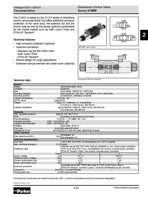
2Technical dataWith electrical connections the protective conductor (PE W ) must be connected according to the relevant regulations.With AMP Junior TimerThe D1MW is based on the D1VW series of directional control valves size NG06, but offers additional corrosion protection of the valve body, the solenoid coil and the anchor tube as well as the typical solenoid con n ections for the mobile market such as AMP Junior Timer and DT04-2P “Deutsch”.Technical features• High corrosion protection (optional)• Solenoid connection:- Standard (as per EN175301-803) - AMP Junior Timer - DT04-2P “Deutsch”•Robust design for rough applications• Extended manual override with rubber cover (optional)Connector DT04-2P “Deutsch”Series D1MW2Ordering CodeDirectionalWet pin 3-chamber Spool Spool Size 4)Only in combination with connection “J” and “W”.D 1WMSeries D1MW2Ordering CodeOther spool types on request.Solenoid options ConnectionDesign series(not required for ordering)Solenoid voltageSurface protectionCodeSolenoid option omitmanual override(Standard)Twithout manual overrideW extended manual override with rubbercoverCode Solenoid voltageK 12 V =J 24 V =Code Connection W 3)Connector as per EN 175301-803J 3)Connector DT04-2P “Deutsch“A 3)2-pin AMP Junior TimerCode Surface protectionomit Standard, only forconnection “J“ and“A“1P 4)Anti corrosion coating acc. to DIN EN ISO 9227 NSS,200 h for extremeconditions.SealsCode Seals N NBR V FPMSeries D1MW2Performance CurvesFlow curves1234567891314Flow [l/min]P r e s s u r e d r o p [b a r ]4812162002060408024121011All characteristic curves measured with HLP46 at 50 °C.1)Only for pressure compensation, no high flow possible.Series D1MW2The diagram below specifies the shift limits for valves with DC & AC solenoids. Valves with spool position “F” or “M” can only be operated up to 70 % of the limits. The specifications apply to a viscosity of 40 mm 2/s and bal-anced flow conditions. The shift limits can be considerably lower at unbalanced flow conditions. To avoid flow rates beyond the shift limits, a plug-in orifice can be inserted in the P-port.Shift limits, DC voltageShift LimitsMeasured with HLP46 at 50 °C, 90 % U nom and warm solenoidsSeries D1MW2DimensionsDimensions with EN 175301-803 Connector B, E, F -styleH, K, M -styleC andD -styleDimensions with 2pin AMP Junior Timer Connector (only C and D -style shown)Dimensions with “Deutsch“ DT04-2P Connector (only C and D -style shown)The space necessary to remove the plug per EN 175301-803, design type AF is at least 15 mm. The torque for the screw M3 of the plug has to be 0.5 to 0.6 Nm.。
THE MW-1 Cyclone RECORD CLEANING MACHINESETUP AND INSTRUCTIONMANUALVPI INDUSTRIES INC., 77 CLIFFWOOD AVE #3BCLIFFWOOD, N.J. 07721**IMPORTANT***IMPORTANT***IMPORTANT***IMPORTANT**YOUR WARRANTEE MAY BE JEOPARDIZED IF YOU DO NOT FOLLOW THESE STEPS WHEN USING YOUR MACHINE ∙Do not use excessive fluid when cleaning.∙Only use VPI fluid. Other fluids may contain chemicals that can damage and warp the machine.∙Drain the catch basin every six records. Open the white clamp on the drain hose and tip the machine back approximately ten degrees. Remember to put something in place to catch the used fluid.∙Shut the vacuum off as soon as the record is dry.∙Clean all fluid spills near the platter. Not doing this could cause the machine to warp. You will not be covered under warrantee if this occurs.∙Adding 25% isopropyl alcohol to VPI RCM fluid made from concentrate will give better cleaning of dirty records, and extend the shelf life of the fluid.FOLLOWING THESE PROCEDURES WILL GIVE YOU MANY YEARS OF USE FROM YOUR CLEANING MACHINE. INTRODUCTIONYour new MW-1 record cleaning machine is capable of giving you many years of trouble-free performance. The MW-1 will microscopically clean all vinyl analog records. (A special adapter and Vacuum Pickup Tube are available for cleaning seven-inch 45-rpm records and ten-inch 78-rpm records). Older 78-rpm shellac records can be cleaned using special VPI fluid. Alcohol based cleaners must never be used on shellac records.1.PRELIMINARY REMARKS∙Save the carton, all internal fillers, and plastic bags.∙Claims for shipping damage can only be filed by the recipient. If damage has occurred, save the carton for inspection by the carrier.Electrical Requirements:MW-1’s are designed to run on 115 Volts AC, 60 Hz or 230 Volts AC, 50 Hz. The shipping carton shows which is the correct voltage for your unit. To prevent electric shock, always plug the MW-1 into a grounded outlet.CAUTION: TO PREVENT FIRE OR SHOCK HAZARD, DO NOT EXPOSE THIS UNIT TO RAIN, OR MOISTURE BEYOND THAT SPECIFIED IN THESE INSTRUCTIONS.2.UNPACKING∙Before lifting the MW-1, remove the plastic bag containing the cleaning fluid and brush. When putting it down, be careful that the waste hose is not caught. Remove the power cord from the box.∙If the hinged, smoked plastic cover has a paper protective covering, do not remove it now. Wait until instructed to do so later.3.UPON RECEIVING YOUR RECORD CLEANER:INITIAL CHECK-OUT PROCEDURE∙Examine the Vacuum Pickup Assembly. Make sure that it shows no signs of damage. Set the assembly aside in a safe, clean place for now.∙Plug the MW-1 into a grounded outlet, which provides the voltage required by your MW-1 as specified on the carton. With the cover open, turn on the switch labeled “turntable.” The turntable is rotated by high torque, 100:1 gear motor and some gear noise is perfectly normal.∙With the cover still open, turn on the switch labeled VACUUM. Your MW-1 is working properly if you hear a loud rushing sound similar to what you would expect from a household vacuum cleaner.∙Turn off both switches.∙Place your MW-1 on a clean dry surface. Allow at least a two-inch clearance behind the MW-1 for the vacuum exhaust vent. (If you are using an alcohol-based record cleaning solution, make sure that the surface on which the MW-1 is on and that is behind its vent CANNOT be marred by alcohol.)Note: The MW-1 will perform best if it is on a reasonably level surface. It is possible for the cleaning fluid to drip over the edge of the record being cleaned if the machine is too far off level.4.PROPER RECORD CLEANING PROCEDURE –THIS UNIT HAS A THERMAL SHUTOFF ON THE TURNTABLEMOTOR. IF THE TURNTABLE STOPS, GIVE IT TIME TO COOL DOWN, AND IT WILL RETURN TO NORMAL OPERATION.∙Your MW-1 was carefully checked before leaving the factory. HOWEVER, since we have no control over the carrier’s trucks, it is imperative that you test the machine with the first record you clean. For this test, select one dispensable record.∙Lift the cover of your MW-1, place this record on the turntable, and screw on the record clamp. Tighten the clamp just enough to hold the record firmly but not so much that the outer rim of the record bows up (dishes).∙Make sure that the Vacuum Pickup Tube is clear of the turntable and is pointing toward the back of the unit. ∙Flip the switch labeled “FWD.” Squirt some of the cleaning fluid onto the groove area of the record with your right hand while pressing the plastic handled brush against the groove area with the left hand. Make sure to get the bristles wet before pressing hard on the area. Take care not to get cleaning fluid on the record’s label. Use enough fluid so that it form s a continuous film over the entire groove surface. As you gain experience, it will become almost automatic to apply the right amount.∙It is time to determine that your MW-1 properly removes the cleaning fluid. The speed with which it does this will vary throughout the country because of differences in line voltage.∙Swing the Vacuum Pickup Tube counter clockwise over the record so that it is almost pointing at the record spindle. Turn on the VACUUM switch. Let the record turn two times and then while keeping the VACUUM switch on press the “REV” switch for the record to be cleaned in the reverse direction. After another two rotations in the reverse direction switch the vacuum and turntable “OFF”. The Vacuum Pickup Tube will lift off the record and can be swung back to its rest position.∙Two turns is normally sufficient to remove all the fluid and leave the record dry. This depends upon how much fluid was on the record to begin with. The record can be vacuumed for two or more turns. Excessive vacuuming can cause a build-up of static electricity.∙ALWAYS turn off the vacuum before turning off the turntable in order to prevent damage to records. If the record is dry; your machine is working properly. If your cover has paper covering it, you can now peel it off.Unscrew the record clamp, lift the record carefully, and repeat the entire operation on the other side.5.ADDITIONAL TIPS∙Do NOT run this machine without liquid on the record.∙It is very important not to overload your MW-1 with cleaning fluid. If fluid leaks out of the machine, the fluid is not being emptied fast enough. The machine should be tipped back at 10 degrees; the hose clamp on the waste hose released, allowing the waste liquid to run out into a waste container. Do this every six records. ∙Low or high line voltage conditions will change the amount of vacuuming time needed. The lower the line voltage, the longer the drying time will be. Make sure that the Vacuum Pickup Tube is free of debris. Gently wipe it with a clean, lint-free, slightly damp sponge each time you finish using your MW-1.∙The velvet surface of the Vacuum Pickup Tube will not last forever. The rate of wear will vary with the amount of grit on your records and your geographical location. A regular maintenance schedule should be established. You should be able to clean one hundred sides before needing to change velvet surfaces.∙Drying the brush between uses will keep it like new.6.MAINTENANCEA.CHANGING THE VACUUM PICKUP TUBEIn time, the velvet covering on the Vacuum Pickup Tube will wear. It is recommended that the tube be replaced after every 200 cleanings (400 sides). A new tube with velvet covering can be ordered from the factory.To change the Vacuum Pickup Tube, proceed as follows:1.Removing the old tube:∙Lift off the whole Vacuum Pickup Tube assembly (it just lifts straight up). Take care not to lose the spring beneath the assembly.∙Pull the Vacuum Pickup Tube out from the rest of the assembly. A slight twisting motion while pulling may facilitate this.2.Inserting the new tube:∙Handle the new tube carefully. Avoid touching the velvet covering.∙Insert the new tube into the black housing with the velvet surfaces facing down. Insert it only so far that the end of the slot is just very slightly to the outside of the edge of the record. If necessary, use a twisting motion when inserting the new tube.∙Now, check to make sure that the slot between the two velvet surfaces is pointing slightly backwards (away from you). If the slot points directly down, the vacuuming action will not be complete. Rotate the tube as necessary.∙Lift off the Vacuum Pickup Tube assembly once more (remember about that spring!) Turn it over and look through the black housing. You should be able to see the end of the Vacuum Pickup Tube.∙Put the Vacuum Pickup Tube assembly back in place again and put a record on the turntable. Clean the record following the normal procedure. When you are vacuuming the fluid, make sure that the whole of the velvet surface is in contact with the reco7.MW-1 CAUTIONS∙Never use more than 25% alcohol by volume in solution to clean records. Use of VPI Fluid will protect the life of your cleaning machine.∙Use alcohol solution on vinyl records only! For all other records, use distilled water or a non-alcohol record cleaning solution.∙When cleaning shellac 78 r.p.m. records, always use a different Vacuum Pickup Tube and brush from the ones used for vinyl records. Many shellac records were made with a carbide abrasive mixed in with the shellac.∙When using an alcohol cleaning solution. DO NOT use the MW-1 near a fire, open flame or burning cigarette, pipe, cigar, etc. The vaporized alcohol in the vacuum exhaust may ignite explosively.VPI INDUSTRIES, INC. LIMITED WARRANTYVPI Industries Inc. (VPI) warrants this unit against defects in materials and/or workmanship for 90 days from the date of purchase by the original retail purchaser. VPI’s sole obligation under this warranty is limited to the repair or replacement, at VPI’s option, of any part(s) found to be defect ive.VPI’s obligation to repair or replace defective parts is the purchaser’s sole and exclusive remedy, and VPI shall not be liable for any direct or indirect injury and/or property damage arising out of the use of the product or defect in or failure of the product.This warranty does not extend to any unit whose serial number has been defaced or altered, or to any product which VPI determines contains a defect of malfunction due to incorrect installation, modification, misuse or servicing by the purchaser, or service technician not authorized by VPI to perform such service. It does not cover trivial or cosmetic defects which do not impair the unit’s normal function.VPI reserves the right to make changes in this product without assuming any obligation to install such change in any product previously manufactured.This warranty to repair or replace defective parts is in lieu of all other express or implied warranties of merchantability or fitness for a particular purpose. There are no warranties that extend beyond the description herein.Some states do not allow exclusion of implied warranties or limitation of incidental or consequential damages, so the above exclusion or limitations may not apply to you. This warranty gives you specific legal rights and you may also have other rights which vary from state to state.Register your Product Online:/warranty/。
MMB万用表伴侣Multimeter Buddy 用户手册User’s Manual用户手册的注意事项:⏹本用户手册如有改变,恕不通知,随时更正,查阅时请以最新版本为准。
请参照封面最下方的用户手册版本号。
⏹若用户发现用户手册中有错误、遗漏等,请与本公司联系。
⏹本公司不承担由于用户错误操作所引起的事故和危害。
⏹本说明书所讲述的功能,不作为将产品用做特殊用途的理由。
MMB万用表伴侣用户手册Multimeter Buddy User’s Manual 警告使用MMB前,请先阅读IntroductionMMB万用表伴侣是一种用电池供电或外部AC/DC电源适配器供电的手持式高精度信号源,可用于输出各种规格的工业信号。
请参阅下表:“输出功能汇总”除了表 1 中的功能以外,MMB还具有以下特点和功能:◆自动电源切换:可通过接通外部AC/DC电源适配器持续工作,无外接电源时,使用电池供电(4节1.5V AA电池)◆电池电量检测:实时监测电池供电并提示用户当前电量◆保存常用输出:可存储和读取多达64组常用输出◆多信息液晶显示:含有输出值、信号类型、电源信息、内存信息等各种提示内容;上下双排显示方便设置和调用常用输出值◆组合按键:不仅可通过数字键键入输出值,还可以通过方向键实现方便的输出值调整◆PC Suite同步软件※:轻松实现仪表的校准、设置和输出等各种功能表1:输出功能汇总目录一.注意事项 (1)二.型号规格 (2)三.技术规格 (3)3.1 标准设备列表 (3)3.2 技术指标 (4)四.外形及接线 (7)4.1 外形尺寸 (7)4.2 液晶显示 (8)4.3 按键说明 (9)4.4 接线说明 (9)4.5 关于精度的说明 (11)五.使用前须知 (13)5.1 使用前的注意事项 (13)5.2 电池使用须知 (13)5.3 安装和更换电池 (14)5.4 电池电量和供电状态指示 (15)六.仪表运行与操作 (15)6.1 开机/关机 (15)6.2 操作构成 (16)6.3 常规操作说明 (16)6.3.1开机 (15)6.3.2切换输出信号类型 (17)6.3.3修改并输出设定值(非频率类信号) (18)6.3.4存储常用输出值(非频率类信号) (21)6.3.5读取常用输出值(非频率类信号) (22)6.3.6频率类信号操作 (24)6.4 参数设置说明 (28)6.4.1密码校验 (27)6.4.2仪表参数设置 (28)6.4.3标定功能 (29)一. 注意事项为了避免触电、伤害、损坏MMB ,或其它设备,请严格遵守所有设备安全规程!必须依照本用户手册(User’s Manual )的规定使用MMB 。
OWNER'S MANUALMODELS MM1, MM1C - HEAT STATIONSupplier Name:MARSHALL AIR SYSTEMS, INC.Address: 419 Peachtree Drive SouthCharlotte, NC 28217Model#: ___________________Serial #': _________________________________________________________Date Received: ___________________Date Installed: ___________________Telephone #: 704-525-6230800-722-3474 Customer ServiceFax #: 704-525-6229Service Referral #: 800-722-3474Local Service: ___________________Local Service #: ___________________MANUFACTURER'S INTRODUCTION The Model MM1 Heat Station features Marshall's own ThermoGlo™ heating technology. Heat radiates from every square inch of the upper flat plate heating surface. This eliminates the need to clean intricate calrod, wire and reflector assemblies. This unit is equipped with an accessory 120 volt receptacle at the back which is fused for a maximum of 5 amperes. It may be used for powering a timer. This receptacle is furnished only on Model MM1. The MM1C Heat Station is equipped with an infinite switch to control the temperature on the ThermoGlo™. GENERAL SPECIFICATIONSModels: MM1, MM1C Heat StationHeight: 19-1/4"Width: 13"Depth: 23-1/4"Electrical: 110/120 volts, AC 840 watts,50/60 Hz, 7 amps and up to 5amps on accessory receptacle220/240 volts, AC 900 watts,50/60 Hz, no accessoryreceptaclePower Cord: 6 ft 3 wire ground type UL rated Weight: 25 lbs.Approvals: UL and NSF110843MM1 RV082799Copyright © 1999 Marshall Air Systems, Inc. All Rights Reserved.MODELS MM1, MM1C - HEAT STATIONTABLE OF CONTENTSINSTALLATION (1)DAILY CHECKLIST AND CLEANING GUIDE (1)MONTHLY MAINTENANCE (1)TROUBLESHOOTING CHART (2)REPLACEMENT PARTS LIST AND ILLUSTRATION (3)THERMOGLO™ & HEATED HOLDING CABINET LIMITED WARRANTY (4)THERMOGLO™ & HEATED HOLDING CABINET WARRANTY RETURN PROCEDURES (5)ILLUSTRATIONSTIMER MOUNTING............................................................................FIGURE 1, PAGE 2 PARTS LIST ILLUSTRATION ............................................................FIGURE2, PAGE 3 WIRING SCHEMATIC (MM1 120V)............................................................ DWG 110266 WIRING SCHEMATIC (MM1 240V)............................................................ DWG 118272 WIRING SCHEMATIC (MM1C 120V).......................................................... DWG 120378 (with infinite switch, without receptacle)WIRING SCHEMATIC (MM1C 120V).......................................................... DWG 118710 (without receptacle and fuse)110843MM1 RV082799Copyright © 1999 Marshall Air Systems, Inc.All Rights Reserved.INSTALLATIONPRE-INSTALLATIONThe Heat Station is packaged to minimize the risk of shipping damage. Immediately upon receipt, make certain to inspect the unit for damage. FILE ALL CLAIMS WITH THE FREIGHT CARRIER.FINAL INSTALLATION1. Unpack unit and remove all protective paper or plastic covering from metal parts.2. Place heat station on stable base.3. If unit includes optional timer brackets, see Timer Mounting Instructions (Figure 1, page 2).4. Plug unit into an AC 120V receptacle for 120V unit or 240V receptacle for 240V unit.DAILY CHECKLIST AND CLEANING GUIDETO USE THE HEAT STATION1. Turn on the power switch.2. Top of switch is red, in on position, indicating power is going to the heater.3. The unit is ready to use after a 15 minute preheat period.CLEANING CHECKLIST1. Turn off the unit and allow it to cool for 30 minutes.2. Pans, lids and wire grates should be removed, washed in the dish machine, rinsed and sanitized.3. Clean unit and base with a damp cloth and cleaner degreaser. DO NOT IMMERSE UNIT IN WATER!DO NOT USE CAUSTIC CLEANING SOLUTIONS!4. Allow sufficient drying time before attempting to use.MONTHLY MAINTENANCEFollow the daily cleaning checklist; there are no periodic adjustments. The only user-replacement item is the5 amp fuse located just below the accessory receptacle only on 120V unit. If this fuse blows do the following:1. Unplug the unit.2. Remove the fuse by unscrewing the fuse cover.3. Replace the fuse with a manufacturer's approved replacement part.110843MM1 RV082799Copyright © 1999 Marshall Air Systems, Inc.All Rights Reserved. 1TROUBLESHOOTING CHART** DISASSEMBLING HEATER VOIDS WARRANTY **Identify problem in the left column and look for probable cause and solution in right hand column. Probable causes listed in the order they are most likely to happen. This sequence should be used to isolate the problem.PROBLEM PROBABLE CAUSE SOLUTION1. No Heat Unplugged Plug inCircuit breaker is tripped Reset breaker; call electrician if tripped twiceCord/plug defective Replace cord/plug Defective power switch Replace switchDefective heating unit Assembly Call Marshall Customer Service 800-722-34742. No power at accessoryreceptacle (only on Model MM1)Fuse blown Replace fuseAccessory appliance draws morethan 5 amps Discontinue using large appliance110843MM1 RV082799Copyright © 1999 Marshall Air Systems, Inc.All Rights Reserved.2MODELS MM1, MM1C - HEAT STATION REPLACEMENT PARTS LISTITEM PART NO.DESCRIPTION1501864Rocker Switch (MM1 MODELS ONLY)500196Infinite Control (MM1C MODELS ONLY)500978Infinite Control Knob (MM1C MODELS ONLY) 2110590 6 Ft. Cord w/Plug3501193Cord Strain Relief4500062Fuse 5 amp (only on 120V unit)5110593Receptacle (only on 120V unit)6500068Fuse Holder (only on 120V unit)7110579Heat GuardOptional110539Timer Brackets (see Figure 1, page 2) REPLACEMENT PARTS ILLUSTRATION110843MM1 RV0827993Copyright © 1999 Marshall Air Systems, Inc.All Rights Reserved.THERMOGLO™ AND HEATED HOLDING CABINET LIMITED WARRANTY MARSHALL AIR SYSTEMS, INC., ("Marshall") warrants to the first purchaser ("Purchaser") all new equipment of its manufacture to be free of defects in material and factory workmanship for a period of one year from date of shipment provided that (i) the equipment is installed in the Continental United States, Canada or Hawaii and operated according to the Owner's Manual while located at the original address of installation, (ii) the warranty registration card has been completed and returned to the factory within fifteen (15) days after installation. Marshall's obligation under this warranty is limited to the repair or replacement at its option of any defective part. It is understood that Marshall's obligation with respect to equipment located outside the Continental United States, Canada or Hawaii is limited to replacement parts only.Because Marshall does not and cannot control Purchaser's installation, use, and maintenance of equipment manufactured by Marshall, this warranty DOES NOT COVER:1. Any equipment calibration.2. Switches.3. Plugs and cords.4. Blown fuses or bulbs.5. Any component disassembled in the field or that has broken seals.6. Any replacement parts used on the equipment which are not purchased from Marshall.7. Accessory components not installed and/or manufactured by Marshall.8. Water or grease accumulation, which will cause electrical failures.9. Labor, except that provided at Marshall's factory.10. Damage due to improper or lack of cleaning, abuse and/or service.SHIPPING DAMAGE must be reported to the carrier and is not covered under this warranty. Marshall will not be liable for damage as a result of improper installation, misuse, abuse, alteration of original design, incorrect voltage, unauthorized service, breakage of fragile items, or any other damage caused by an act out of Marshall's control.The effect of corrosion, fire, and normal wear on the equipment or component parts is not covered by this warranty. This warranty does not cover cooking performance, smoke capture or holding temperatures which is a function of food types, textures, temperatures, equipment line ups and other variables chosen by the Purchaser and over which Marshall has no control. This warranty does not apply to damage caused by accident or to damage caused by the negligence of Purchaser or the employees of Purchaser or to damage caused by lightning generated electrical current or any other Act of God whatsoever. This warranty does not apply to any equipment bearing a serial number which has been tampered with or altered. Marshall reserves the right to accept or reject any such clai m in whole or in part. Marshall will not accept the return of any product without prior written approval from Marshall, and all such approved returns shall be made at Purchaser's sole expense.THIS WARRANTY IS IN LIEU OF ALL OTHER WARRANTIES, EXPRESS OR IMPLIED, INCLUDING THE IMPLIED WARRANTY OF MERCHANTABILITY AND THE IMPLIED WARRANTY OF FITNESS FOR A PARTICULAR PURPOSE, OR PATENT OR OTHER INTELLECTUAL PROPERTY RIGHT INFRINGEMENT, AND EXCEPT FOR THE EXPRESS WARRANTY CONTAINED HEREIN, THE EQUIPMENT IS SOLD "AS IS." REMEDIES UNDER THIS WARRANTY AND UNDER ANY WARRANTY THAT MAY SURVIVE THE DISCLAIMER OF WARRANTIES ARE LIMITED EXCLUSIVELY TO THOSE REMEDIES DESCRIBED ABOVE. NO OTHER REMEDY IS AVAILABLE UNDER THIS WARRANTY OR ANY OTHER WARRANTY. NEITHER THIS WARRANTY NOR ANY OTHER WAR RANTY COVERS, AND MARSHALL WILL NOT BE RESPONSIBLE FOR, ANY INCIDENTAL OR CONSEQUENTIAL DAMAGES, INCLUDING BUT NOT LIMITED TO THE COST OF DISASSEMBLY AND SHIPMENT OF THE EQUIPMENT, PRODUCTION OR PRODUCT LOSSES, INJURY TO OTHER PROPERTY, OR LOST PROFITS RESULTING FROM THE USE OF OR INABILITY TO USE THE PRODUCTS OR FROM THE PRODUCTS BEING INCORPORATED IN OR BECOMING A COMPONENT OF ANY OTHER PRODUCT OR GOODS, OR OTHER LOSSES. WHERE. DUE TO OPERATION OF LAW, CONSEQUENTIAL AND INCIDENTAL DAMAGES CANNOT BE EXCLUDED, THEY ARE EXPRESSLY LIMITED IN AMOUNT TO THE PURCHASE PRICE OF THE EQUIPMENT.FOR INTERNATIONAL INSTALLATIONS - PLEASE CONTACT YOUR LOCAL MARSHALL AIR SYSTEMS RECOGNIZED DISTRIBUTOR.110843MM1 RV082799Copyright © 1999 Marshall Air Systems, Inc.4All Rights Reserved.THERMOGLO™AND HEATED HOLDING CABINET WARRANTYRETURN PROCEDURES:I. RETURN GOODS AUTHORIZATION FOR PARTSFor prompt warranty parts replacement and RGA processing, please call Marshall's Customer ServiceDepartment at 800-722-3474 or 704-525-6230 for assistance. In all cases, a Return Goods Authorization (RGA) number must be issued by Marshall Air Systems, Inc. Unauthorized returns will not be processed.Option #1: Purchaser to return part(s) prepaid to Factory, Marshall to repair or replace at ownexpense if defective, and ship part(s) back to Purchaser prepaid.Option #2: Marshall to furnish replacement part(s) freight prepaid with or without requesting return ofthe defective part(s).Option #3: Purchaser may obtain replacement part(s) from recognized service agency.II. NON-WARRANTY RETURNS:All items returned for customer cancellations are subject to a 20% restocking fee. In the event of an error by Marshall Air Systems, Inc., a Returned Goods Authorization will be issued for full credit. Custom fabricated parts are not returnable.FOR INTERNATIONAL INSTALLATIONS -- PLEASE CONTACT YOUR LOCAL MARSHALLAIR SYSTEMS RECOGNIZED DISTRIBUTOR.110843MM1 RV082799Copyright © 1999 Marshall Air Systems, Inc.5All Rights Reserved.。
MMW-1微机控制立式万能摩擦磨损试
验机使用说明书
目录
1.试验机主要用途 (1)
2.试验机主要技术规格 (1)
3.试验机结构简述 (2)
4.试验机面板系统的操作 (6)
5.试验机的拆箱、吊运、安装、调试与润滑 (8)
1:试验机主要用途
M M W-1型立式万能摩擦磨损试验机,其主要用途与功能均与美国F A L E X6#型多功能试样测试试验机相似(M n l t i-s p e c i m t n.t e t M a c h i n e),它是研制开发各种耐磨损材料的模拟评定测试试验机。
该机以一定的摩擦形式在一定的接触压力下,具有脉宽无级调速系统,可在极低速或高速条件下,用来评定润滑剂,金属,塑料,涂层,橡胶,陶瓷,等材料的摩擦磨损性能。
M M W-1型试验机在摩擦学各个专业技术领域,石油化工,机械,能源,冶金,航天,各大专院校,研究院(所)等部门具有广泛的应用前途。
2:试验机的主要技术规格
1.试验力
3:试验机结构简述(如图1)
立式万能摩擦磨损试验机是由主轴驱动系统,摩擦副专用夹具,油盒与加热器,试验力传感器,摩擦力矩测定系统,摩擦副下副盘升降系统,弹簧式微机施力系统,操纵面板系统等部分组成。
它们都安装在以焊接机座为主体的机架内。
机座的右上方是试验机操作显示系统,左上方是主轴驱动系统和油盒,摩擦副,各种传感仪器等,机座的左下部是试验机弹簧式施力系统和微机自动加荷系统,右下部是工具箱,机座的前后及左侧有门,打开时能清楚看到内部机构,以便进行调试检修。
3.1主轴及其驱动系统
主轴(1)是由S-C Z K Y无级直流电机(2)和P W M C脉宽调速控制系统组成,该系统电机的额定力矩为5N·m,脉宽调速范围为10-1500r/m i n,无级恒扭矩,高速精度为1%.该直流电机最大功
率约 1.2K w,在主轴(1)和直流电机(2)上部
,分别装有从动和主动特制的圆弧齿形带轮(3)、(4),通过圆弧齿同步带(5)把直流电机的功率传递到主轴上。
由于应用了脉宽调速系统使其在低转速下具有高的传动力矩,它完全改变了可控硅无级变速系统在低转速下传动力成倍递减的特点。
3.2油盒与摩擦副加热升温系统:
主轴(1)是空心轴,其最下端有1:7的锥孔,可以安装各种各样的摩擦副上夹头,例如,销盘夹头(10)和销盘摩擦副(11)、(12),空心主轴内有拉杆(6),当销盘摩擦副等夹头装入主轴锥孔内,旋紧拉杆(6)可确保主轴与各个摩擦副上夹头在主轴锥孔内不产生任何相对滑动。
油盒加热系统有两套,分别是不锈钢套式加垫圈(13)和加热板(14),均在220V,条件下,通过继电器对试验温度从室温~100℃进行数显控制与报警,进行工作,在两种油盒加热器中都装有P t—100Ω标准铂电阻。
3.3下导向主轴与下摩擦副副盘及摩擦力矩传感系统。
下导向主轴(15)副盘(16),直线球轴承(17),两个径向球轴承(18),试验力传感器(19),摩擦力传感器(20),止推球轴承(21),背紧螺母(22),滚花螺钉23),再更换夹头与装卸各种摩擦副时必须操作(22)与(23),直线球轴承(17)可使下导向主轴(15)上下运动,摩擦力小,轻便灵活,它可使在施加试验力时具有较高的灵敏度,轴承(18)可使传递摩擦力时数显准确可靠。
本机力值标定,是由专用工具和标准牛顿砝码检定,以确保本试验机与摩擦力矩按计量法规定传递精度准确可靠。
3.4弹簧式微机施力系统
试验机试验力的施加是通过弹簧式施力结构与微机控制步进电机系统自动进行,步进电机(30)通过一对径向止推球轴承
(31),(32),传递一对减速比为80:1的蜗杆(28)蜗轮(29)运行
副。
蜗轮(29)固定着一根丝杠(25),由一对径向止推滚子轴承(27)使下螺母施力板上下移动(有两根固定立柱作导向)压缩施力弹簧(24),通过上施力板,荷重传感器(19)把试验力施加到不同的摩擦副上产生接触压力,并按要求进行试验。
操纵试验力控制按钮,通过微机控制自动加载系统可实现按一定速率加载。
行程限位开关可在试验结束后自动卸载后起限位停机作用。
3.5摩擦副部分
3.6试验机控制面板系统
试验机的控制箱在机座上方右侧是电脑显示器。
打开后盖可看到电脑控制箱,通过相应参数的设置可实现对试验机的操作。
4:试验机面板系统的操作
试验机的操作面板(如图7):
4.1试验操作:
面板如图2所示,首先应接通试验机电源(电源为220V、50H z交流电),按下电源开按扭,及显示器旁的电脑主机开关,从桌面上打开控制系统。
试验之前首先装好试样,选择试验方法,对试验力、摩擦力、进行清零。
并对各参数进行设置。
先手动调整,通过滚花螺钉使试样上升,当上下摩擦副接近时,选择自动加载,当试验力值稳定后试验开始,时间、摩擦力等开始计数。
4.2具体操作可以参照以下步骤:
1.接通电源,检查电源是否正常,若正常,进行第二步操作,若
不正常,检查供电电源及强电板上的空气开关是否已接通。
2.查看主轴轴旋转方向是否正确,该试验机的主轴不可逆转,既
从上往下看是主轴为顺时针旋转。
3.安装试样,具体安装方式可参照图2-图6。
4.试样安装完毕,将上试样夹头镶在主轴下端锥孔内,旋紧拉杆,
下试样放入试样座相应位置,手动旋转滚花螺钉,让下导向主轴上升,使上下摩擦副相互接近。
5.选择试试验验方法,进行参数设定,调整加载速度,按下自动
加载按扭,试验力值稳定后,按下开始按扭试验开始。
6.当做高温长时四球磨损试验时,应将高温油盒安装至试验副盘
上之后接通温度控制器电源。
当温度快要到达设定温度时,手动旋转滚花螺钉,使下导向轴上升,让油盒上升到接近弹簧夹头位置,进行参数设置,继续升温过程中使用自动控制模式达到设定力值。
当温度到达设定温度之后,按下开始按扭,试验开始。
(温度设定参数已完成,不必改变其中的参数)。
7.试验结束后,将试验力设为“零”,系统会自动卸载;或点下
手动加载,将控制条向左拉。
当试验力下降到“零”时,点击停止按扭,手动旋转滚花螺钉,使导向主轴下降,取下试样,分析试验结果。
8.如作低速试验,请将驱动装置更换为1:20减速装置。
9..
10.
11.。