FCC_Part15_RE_Fail问题改善2015.12.1
- 格式:docx
- 大小:1.06 MB
- 文档页数:5
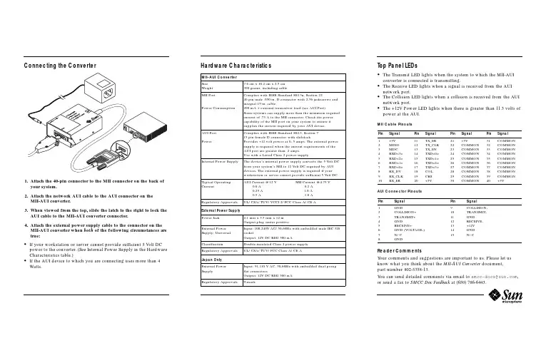
Connecting the Converter1.Attach the40-pin connector to the MII connector on the back ofyour system.2.Attach the network AUI cable to the AUI connector on theMII-AUI converter.3.When viewed from the top,slide the latch to the right to lock theAUI cable to the MII-AUI converter connector.4.Attach the external power supply cable to the connector on theMII-AUI converter when both of the following circumstances are true:•If your workstation or server cannot provide sufficient5Volt DC power to the converter.(See Internal Power Supply in the Hardware Characteristics table.)•If the AUI device to which you are connecting uses more than4 Watts.Hardware Characteristics Top Panel LEDs•The Transmit LED lights when the system to which the MII-AUIconverter is connected is transmitting.•The Receive LED lights when a signal is received from the AUInetwork port.•The Collision LED lights when a collision is received from the AUInetwork port.•The+12V Power LED lights when there is greater than11.3volts ofpower at the AUI.MII Cable PinoutsAUI Connector PinoutsReader CommentsYour comments and suggestions are important to us.Please let usknow what you think about the MII-AUI Converter document,part number802-5358-13.You can send detailed comments via email to*****************,or send a fax to SMCC Doc Feedback at(650)786-6443.MII-AUI ConverterSizeWeight7.6cm x10.2cm x2.5cm300grams,including cableMII PortPower ConsumptionComplies with IEEE Standard802.3u,Section2240pin male.050in.D connector with2-56jackscrews andintegral19in.cable.200mA+external transceiver load(see AUI Port)Some systems can supply more than the minimum requiredcurrent of.75A to the MII connector.Check the powercapability of the MII port on your system to ensure itsupplies the current required by your AUI device.AUI PortPowerComplies with IEEE Standard802.3,Section715pin female D connector with slidelockProvides+12volt power at0-.5amps.The external powersupply is required when the current requirements of theAUI port are greater than.2amps.Use with a Listed Class2power supply.Internal Power Supply The device’s internal power supply converts the5Volt DCfrom your system’s MII to12Volt DC required by AUIdevices.The external power supply is required if yourworkstation or server cannot provide sufficient5Volt DC.Typical OperatingCurrentAUI Current@12V MII Current@4.75V0.0A0.2A0.25A 1.0A0.5A 1.8ARegulatory Approvals UL/CSA/TUV/VCCI2/FCC Class A/CE AExternal Power SupplyPower Jack 2.1mm x5.5mm x12mOutput plug center positiveExternal PowerSupply:UniversalInput:100-240V AC/50-60Hz with embedded male IEC320socketOutput:12V DC REG500mAClassification Double-insulated Class2power supplyRegulatory Approvals UL/CSA/TUV/FCC Class A/CE AJapan OnlyExternal PowerSupplyInput:91-110V AC,50-60Hz with embedded dual prongflat connectorsOutput:12V DC REG500mARegulatory Approvals T-markPin Signal Pin Signal Pin Signal Pin Signal12345678910+5VMDIOMDCRXD<3>RXD<2>RXD<1>RXD<0>RX_DVRX_CLKRX_ER11121314151617181920TX_ERTX_CLKTX_ENTXD<0>TXD<1>TXD<2>TXD<3>COLCRS+5V21222324252627282930+5VCOMMONCOMMONCOMMONCOMMONCOMMONCOMMONCOMMONCOMMONCOMMON31323334353637383940COMMONCOMMONCOMMONCOMMONCOMMONCOMMONCOMMONCOMMONCOMMON+5VPin Signal Pin Signal12345678GNDCOLLISION+TRANSMIT+GNDRECEIVE+GND(VOLTAGE-)N/CGND9101112131415COLLISION-TRANSMIT-GNDRECEIVE-+12VGNDN/CRecycled PaperFCC Class A Notice —United StatesThis device complies with Part 15of the FCC Rules.Operation is subject to the following two conditions:1.This device may not cause harmful interference.2.This device must accept any interference received,including interference that may cause undesired operation.Note –This equipment has been tested and found to comply with the limits for a Class A digital device,pursuant to Part 15of the FCC Rules.These limits are designed to provide reasonable protection against harmful interference when the equipment is operated in a commercial environment.This equipment generates,uses and can radiate radio frequency energy and,if not installed and used in accordance with the instruction manual,may cause harmful interference to radio communications.Operation of this equipment in a residential area is likely to cause harmful interference in which case the user will be required to correct the interference at his own expense.Shielded CablesConnections between the workstation and peripherals must be made using shielded cables in order to maintain compliance with FCC radio frequency emission limits.ModificationsModifications to this device,not approved by Sun Microsystems,Inc.,may void the authority granted to the user by the FCC to operate this equipment.Canadian Class A Notice -Avis Du Minestère des Communications,Classe AThis Class A digital apparatus meets all requirements of the Canadian Interference-Causing Equipment Regulations.Cet appareil numérique de la classe A respecte toutes les exigences du Règlement sur le matériel brouilleur du Canada.MII-AUI ConverterAbout the MII-AUI ConverterThe MII-AUI Converter allows the use of an existing AUI (Attachment Unit Interface)network connection with a system that uses an MII (Media Independent Interface)for its network connection.The converter is compatible with Sun™Ultra™platforms and SunFastEthernet™adapters with an available MII port.Part Number: 802-5358-13Revision A of November 1997©1997Sun Microsystems,Inc.All rights reserved.Sun,Sun Microsystems,the Sun Logo,SunSoft,and Solaris are trademarks or registered trademarks of Sun Microsystems,Inc.in the United States and in other countries.©1997Sun Microsystems,Inc.Tous droits réservés.Sun,Sun Microsystems,le logo Sun,SunSoft,et Solaris sont des marques déposées ou enregistrées de Sun Microsystems,Inc.aux Etats-Unit et dans d’autres pays.。
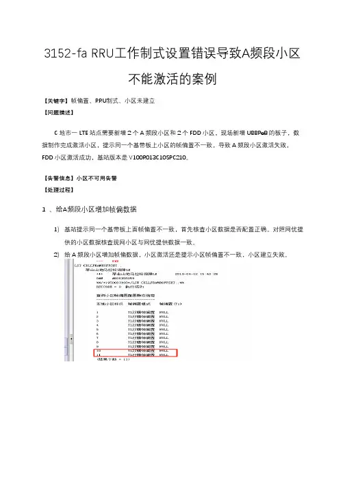
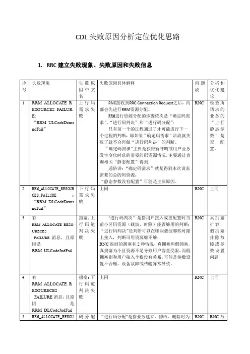
3152-fa RRU工作制式设置错误导致A频段小区不能激活的案例【关键字】帧偏置、RRU制式、小区未建立【问题描述】C地市一LTE站点需要新增2个A频段小区和2个FDD小区,现场新增UBBPe8的板子,数据制作完成激活小区,提示同一个基带板上小区的帧偏置不一致,导致A频段小区激活失败,FDD小区激活成功,基站版本是V100R013C10SPC210。
【告警信息】小区不可用告警【处理过程】1 、给A频段小区增加帧偏数据1)基站提示同一个基带板上面帧偏置不一致,首先核查小区数据是否配置正确。
对照网优提供的小区数据核查现网小区与网优提供数据一致。
2)给A频段小区增加帧偏数据,小区激活还是提示小区帧偏置不一致,小区建立失败。
2、将A频段小区绑定到单独一块基带板上面1)再次新增一块基带板,将A频段小区单独绑定到一块基带板上面。
小区激活,提示载波组合超出RRU载波规格。
2)核查RRU配置数据发现,RRU的工作制式配置为TL模式,将TL模式修改成TDL模式。
小区激活成功。
3)再次将A频段小区和FDD小区绑定到一起,小区激活成功。
3、分析:C市LTE基站FDD小区和A频段小区共基带板导致小区未能建立成功的问题,根因是RRU 制式配置错误。
3152-fa的RRU如果只开A频段,那么RRU的工作制式应该配置成TDL模式,不能配置成双模TL模式。
【根因】RRU工作制式配置错误,导致A频段小区建立失败。
【解决方案】将需开A频段小区的RRU的工作制式改为TDL模式。
【总结】在开通A频段小区时,需要按照站点解决方案正确设置RRU 3152-FA工作制式为TDL。
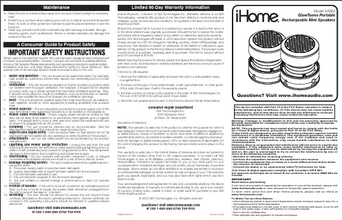
Using the iHM62To unlock and expand each speaker, grip the top and bottom and give a small twist counter-clockwise. DO NOT pull hard once open, as the built in spring will automatically extend the speaker to its proper position.Press speaker down from the top and twist clockwise to lock in place when not in use.Connecting the iHM62The iHM62 is powered by a rechargeable battery in each speaker. When the blue power light turns red, or if you start to notice sound distortion at higher volumes, it's time to recharge the battery.• Connect the larger USB plug to a powered USB port, such as that on a computer. The light on each speaker will stay red while charging and turn blue when fully charged.Note: you can continue to listen to the speaker and/or enjoy lighting effects while it is charging- Press the LED lighting effects button to cycle through 3 lighting effects modes: colors cycle, one color, none.Colors Cycle :- LEDs will fade in and out in sequence: blue, green, amber, red, repeat (color cycle is the default when the unit is powered on).One Color :- Press during cycle mode to hold the last color shown Note:LED will shine at full brightness.None :- Enjoy your music without lighting effects.Note: speaker is still on, indicated by power LED.Charging the iHM62LED Lighting Effects:• Connect a mini-USB plug to the input jack on each speaker.• Connect the stereo 3.5mm audio plug to the headphone jack or line-out of any audio device.• Slide the Power Switch of each speaker to the ON position. The blue power light will come on.• Press play on your audio device and adjust its volume to listen to audio.Note: the larger USB plug is used for charging only, not for audio. Please refer to next section for charging instructions.。
Error MessagesF9001 Error internal function call.F9002 Error internal RTOS function callF9003 WatchdogF9004 Hardware trapF8000 Fatal hardware errorF8010 Autom. commutation: Max. motion range when moving back F8011 Commutation offset could not be determinedF8012 Autom. commutation: Max. motion rangeF8013 Automatic commutation: Current too lowF8014 Automatic commutation: OvercurrentF8015 Automatic commutation: TimeoutF8016 Automatic commutation: Iteration without resultF8017 Automatic commutation: Incorrect commutation adjustment F8018 Device overtemperature shutdownF8022 Enc. 1: Enc. signals incorr. (can be cleared in ph. 2) F8023 Error mechanical link of encoder or motor connectionF8025 Overvoltage in power sectionF8027 Safe torque off while drive enabledF8028 Overcurrent in power sectionF8030 Safe stop 1 while drive enabledF8042 Encoder 2 error: Signal amplitude incorrectF8057 Device overload shutdownF8060 Overcurrent in power sectionF8064 Interruption of motor phaseF8067 Synchronization PWM-Timer wrongF8069 +/-15Volt DC errorF8070 +24Volt DC errorF8076 Error in error angle loopF8078 Speed loop error.F8079 Velocity limit value exceededF8091 Power section defectiveF8100 Error when initializing the parameter handlingF8102 Error when initializing power sectionF8118 Invalid power section/firmware combinationF8120 Invalid control section/firmware combinationF8122 Control section defectiveF8129 Incorrect optional module firmwareF8130 Firmware of option 2 of safety technology defectiveF8133 Error when checking interrupting circuitsF8134 SBS: Fatal errorF8135 SMD: Velocity exceededF8140 Fatal CCD error.F8201 Safety command for basic initialization incorrectF8203 Safety technology configuration parameter invalidF8813 Connection error mains chokeF8830 Power section errorF8838 Overcurrent external braking resistorF7010 Safely-limited increment exceededF7011 Safely-monitored position, exceeded in pos. DirectionF7012 Safely-monitored position, exceeded in neg. DirectionF7013 Safely-limited speed exceededF7020 Safe maximum speed exceededF7021 Safely-limited position exceededF7030 Position window Safe stop 2 exceededF7031 Incorrect direction of motionF7040 Validation error parameterized - effective thresholdF7041 Actual position value validation errorF7042 Validation error of safe operation modeF7043 Error of output stage interlockF7050 Time for stopping process exceeded8.3.15 F7051 Safely-monitored deceleration exceeded (159)8.4 Travel Range Errors (F6xxx) (161)8.4.1 Behavior in the Case of Travel Range Errors (161)8.4.2 F6010 PLC Runtime Error (162)8.4.3 F6024 Maximum braking time exceeded (163)8.4.4 F6028 Position limit value exceeded (overflow) (164)8.4.5 F6029 Positive position limit exceeded (164)8.4.6 F6030 Negative position limit exceeded (165)8.4.7 F6034 Emergency-Stop (166)8.4.8 F6042 Both travel range limit switches activated (167)8.4.9 F6043 Positive travel range limit switch activated (167)8.4.10 F6044 Negative travel range limit switch activated (168)8.4.11 F6140 CCD slave error (emergency halt) (169)8.5 Interface Errors (F4xxx) (169)8.5.1 Behavior in the Case of Interface Errors (169)8.5.2 F4001 Sync telegram failure (170)8.5.3 F4002 RTD telegram failure (171)8.5.4 F4003 Invalid communication phase shutdown (172)8.5.5 F4004 Error during phase progression (172)8.5.6 F4005 Error during phase regression (173)8.5.7 F4006 Phase switching without ready signal (173)8.5.8 F4009 Bus failure (173)8.5.9 F4012 Incorrect I/O length (175)8.5.10 F4016 PLC double real-time channel failure (176)8.5.11 F4017 S-III: Incorrect sequence during phase switch (176)8.5.12 F4034 Emergency-Stop (177)8.5.13 F4140 CCD communication error (178)8.6 Non-Fatal Safety Technology Errors (F3xxx) (178)8.6.1 Behavior in the Case of Non-Fatal Safety Technology Errors (178)8.6.2 F3111 Refer. missing when selecting safety related end pos (179)8.6.3 F3112 Safe reference missing (179)8.6.4 F3115 Brake check time interval exceeded (181)Troubleshooting Guide | Rexroth IndraDrive Electric Drivesand ControlsI Bosch Rexroth AG VII/XXIITable of ContentsPage8.6.5 F3116 Nominal load torque of holding system exceeded (182)8.6.6 F3117 Actual position values validation error (182)8.6.7 F3122 SBS: System error (183)8.6.8 F3123 SBS: Brake check missing (184)8.6.9 F3130 Error when checking input signals (185)8.6.10 F3131 Error when checking acknowledgment signal (185)8.6.11 F3132 Error when checking diagnostic output signal (186)8.6.12 F3133 Error when checking interrupting circuits (187)8.6.13 F3134 Dynamization time interval incorrect (188)8.6.14 F3135 Dynamization pulse width incorrect (189)8.6.15 F3140 Safety parameters validation error (192)8.6.16 F3141 Selection validation error (192)8.6.17 F3142 Activation time of enabling control exceeded (193)8.6.18 F3143 Safety command for clearing errors incorrect (194)8.6.19 F3144 Incorrect safety configuration (195)8.6.20 F3145 Error when unlocking the safety door (196)8.6.21 F3146 System error channel 2 (197)8.6.22 F3147 System error channel 1 (198)8.6.23 F3150 Safety command for system start incorrect (199)8.6.24 F3151 Safety command for system halt incorrect (200)8.6.25 F3152 Incorrect backup of safety technology data (201)8.6.26 F3160 Communication error of safe communication (202)8.7 Non-Fatal Errors (F2xxx) (202)8.7.1 Behavior in the Case of Non-Fatal Errors (202)8.7.2 F2002 Encoder assignment not allowed for synchronization (203)8.7.3 F2003 Motion step skipped (203)8.7.4 F2004 Error in MotionProfile (204)8.7.5 F2005 Cam table invalid (205)8.7.6 F2006 MMC was removed (206)8.7.7 F2007 Switching to non-initialized operation mode (206)8.7.8 F2008 RL The motor type has changed (207)8.7.9 F2009 PL Load parameter default values (208)8.7.10 F2010 Error when initializing digital I/O (-> S-0-0423) (209)8.7.11 F2011 PLC - Error no. 1 (210)8.7.12 F2012 PLC - Error no. 2 (210)8.7.13 F2013 PLC - Error no. 3 (211)8.7.14 F2014 PLC - Error no. 4 (211)8.7.15 F2018 Device overtemperature shutdown (211)8.7.16 F2019 Motor overtemperature shutdown (212)8.7.17 F2021 Motor temperature monitor defective (213)8.7.18 F2022 Device temperature monitor defective (214)8.7.19 F2025 Drive not ready for control (214)8.7.20 F2026 Undervoltage in power section (215)8.7.21 F2027 Excessive oscillation in DC bus (216)8.7.22 F2028 Excessive deviation (216)8.7.23 F2031 Encoder 1 error: Signal amplitude incorrect (217)VIII/XXII Bosch Rexroth AG | Electric Drivesand ControlsRexroth IndraDrive | Troubleshooting GuideTable of ContentsPage8.7.24 F2032 Validation error during commutation fine adjustment (217)8.7.25 F2033 External power supply X10 error (218)8.7.26 F2036 Excessive position feedback difference (219)8.7.27 F2037 Excessive position command difference (220)8.7.28 F2039 Maximum acceleration exceeded (220)8.7.29 F2040 Device overtemperature 2 shutdown (221)8.7.30 F2042 Encoder 2: Encoder signals incorrect (222)8.7.31 F2043 Measuring encoder: Encoder signals incorrect (222)8.7.32 F2044 External power supply X15 error (223)8.7.33 F2048 Low battery voltage (224)8.7.34 F2050 Overflow of target position preset memory (225)8.7.35 F2051 No sequential block in target position preset memory (225)8.7.36 F2053 Incr. encoder emulator: Pulse frequency too high (226)8.7.37 F2054 Incr. encoder emulator: Hardware error (226)8.7.38 F2055 External power supply dig. I/O error (227)8.7.39 F2057 Target position out of travel range (227)8.7.40 F2058 Internal overflow by positioning input (228)8.7.41 F2059 Incorrect command value direction when positioning (229)8.7.42 F2063 Internal overflow master axis generator (230)8.7.43 F2064 Incorrect cmd value direction master axis generator (230)8.7.44 F2067 Synchronization to master communication incorrect (231)8.7.45 F2068 Brake error (231)8.7.46 F2069 Error when releasing the motor holding brake (232)8.7.47 F2074 Actual pos. value 1 outside absolute encoder window (232)8.7.48 F2075 Actual pos. value 2 outside absolute encoder window (233)8.7.49 F2076 Actual pos. value 3 outside absolute encoder window (234)8.7.50 F2077 Current measurement trim wrong (235)8.7.51 F2086 Error supply module (236)8.7.52 F2087 Module group communication error (236)8.7.53 F2100 Incorrect access to command value memory (237)8.7.54 F2101 It was impossible to address MMC (237)8.7.55 F2102 It was impossible to address I2C memory (238)8.7.56 F2103 It was impossible to address EnDat memory (238)8.7.57 F2104 Commutation offset invalid (239)8.7.58 F2105 It was impossible to address Hiperface memory (239)8.7.59 F2110 Error in non-cyclical data communic. of power section (240)8.7.60 F2120 MMC: Defective or missing, replace (240)8.7.61 F2121 MMC: Incorrect data or file, create correctly (241)8.7.62 F2122 MMC: Incorrect IBF file, correct it (241)8.7.63 F2123 Retain data backup impossible (242)8.7.64 F2124 MMC: Saving too slowly, replace (243)8.7.65 F2130 Error comfort control panel (243)8.7.66 F2140 CCD slave error (243)8.7.67 F2150 MLD motion function block error (244)8.7.68 F2174 Loss of motor encoder reference (244)8.7.69 F2175 Loss of optional encoder reference (245)Troubleshooting Guide | Rexroth IndraDrive Electric Drivesand Controls| Bosch Rexroth AG IX/XXIITable of ContentsPage8.7.70 F2176 Loss of measuring encoder reference (246)8.7.71 F2177 Modulo limitation error of motor encoder (246)8.7.72 F2178 Modulo limitation error of optional encoder (247)8.7.73 F2179 Modulo limitation error of measuring encoder (247)8.7.74 F2190 Incorrect Ethernet configuration (248)8.7.75 F2260 Command current limit shutoff (249)8.7.76 F2270 Analog input 1 or 2, wire break (249)8.7.77 F2802 PLL is not synchronized (250)8.7.78 F2814 Undervoltage in mains (250)8.7.79 F2815 Overvoltage in mains (251)8.7.80 F2816 Softstart fault power supply unit (251)8.7.81 F2817 Overvoltage in power section (251)8.7.82 F2818 Phase failure (252)8.7.83 F2819 Mains failure (253)8.7.84 F2820 Braking resistor overload (253)8.7.85 F2821 Error in control of braking resistor (254)8.7.86 F2825 Switch-on threshold braking resistor too low (255)8.7.87 F2833 Ground fault in motor line (255)8.7.88 F2834 Contactor control error (256)8.7.89 F2835 Mains contactor wiring error (256)8.7.90 F2836 DC bus balancing monitor error (257)8.7.91 F2837 Contactor monitoring error (257)8.7.92 F2840 Error supply shutdown (257)8.7.93 F2860 Overcurrent in mains-side power section (258)8.7.94 F2890 Invalid device code (259)8.7.95 F2891 Incorrect interrupt timing (259)8.7.96 F2892 Hardware variant not supported (259)8.8 SERCOS Error Codes / Error Messages of Serial Communication (259)9 Warnings (Exxxx) (263)9.1 Fatal Warnings (E8xxx) (263)9.1.1 Behavior in the Case of Fatal Warnings (263)9.1.2 E8025 Overvoltage in power section (263)9.1.3 E8026 Undervoltage in power section (264)9.1.4 E8027 Safe torque off while drive enabled (265)9.1.5 E8028 Overcurrent in power section (265)9.1.6 E8029 Positive position limit exceeded (266)9.1.7 E8030 Negative position limit exceeded (267)9.1.8 E8034 Emergency-Stop (268)9.1.9 E8040 Torque/force actual value limit active (268)9.1.10 E8041 Current limit active (269)9.1.11 E8042 Both travel range limit switches activated (269)9.1.12 E8043 Positive travel range limit switch activated (270)9.1.13 E8044 Negative travel range limit switch activated (271)9.1.14 E8055 Motor overload, current limit active (271)9.1.15 E8057 Device overload, current limit active (272)X/XXII Bosch Rexroth AG | Electric Drivesand ControlsRexroth IndraDrive | Troubleshooting GuideTable of ContentsPage9.1.16 E8058 Drive system not ready for operation (273)9.1.17 E8260 Torque/force command value limit active (273)9.1.18 E8802 PLL is not synchronized (274)9.1.19 E8814 Undervoltage in mains (275)9.1.20 E8815 Overvoltage in mains (275)9.1.21 E8818 Phase failure (276)9.1.22 E8819 Mains failure (276)9.2 Warnings of Category E4xxx (277)9.2.1 E4001 Double MST failure shutdown (277)9.2.2 E4002 Double MDT failure shutdown (278)9.2.3 E4005 No command value input via master communication (279)9.2.4 E4007 SERCOS III: Consumer connection failed (280)9.2.5 E4008 Invalid addressing command value data container A (280)9.2.6 E4009 Invalid addressing actual value data container A (281)9.2.7 E4010 Slave not scanned or address 0 (281)9.2.8 E4012 Maximum number of CCD slaves exceeded (282)9.2.9 E4013 Incorrect CCD addressing (282)9.2.10 E4014 Incorrect phase switch of CCD slaves (283)9.3 Possible Warnings When Operating Safety Technology (E3xxx) (283)9.3.1 Behavior in Case a Safety Technology Warning Occurs (283)9.3.2 E3100 Error when checking input signals (284)9.3.3 E3101 Error when checking acknowledgment signal (284)9.3.4 E3102 Actual position values validation error (285)9.3.5 E3103 Dynamization failed (285)9.3.6 E3104 Safety parameters validation error (286)9.3.7 E3105 Validation error of safe operation mode (286)9.3.8 E3106 System error safety technology (287)9.3.9 E3107 Safe reference missing (287)9.3.10 E3108 Safely-monitored deceleration exceeded (288)9.3.11 E3110 Time interval of forced dynamization exceeded (289)9.3.12 E3115 Prewarning, end of brake check time interval (289)9.3.13 E3116 Nominal load torque of holding system reached (290)9.4 Non-Fatal Warnings (E2xxx) (290)9.4.1 Behavior in Case a Non-Fatal Warning Occurs (290)9.4.2 E2010 Position control with encoder 2 not possible (291)9.4.3 E2011 PLC - Warning no. 1 (291)9.4.4 E2012 PLC - Warning no. 2 (291)9.4.5 E2013 PLC - Warning no. 3 (292)9.4.6 E2014 PLC - Warning no. 4 (292)9.4.7 E2021 Motor temperature outside of measuring range (292)9.4.8 E2026 Undervoltage in power section (293)9.4.9 E2040 Device overtemperature 2 prewarning (294)9.4.10 E2047 Interpolation velocity = 0 (294)9.4.11 E2048 Interpolation acceleration = 0 (295)9.4.12 E2049 Positioning velocity >= limit value (296)9.4.13 E2050 Device overtemp. Prewarning (297)Troubleshooting Guide | Rexroth IndraDrive Electric Drivesand Controls| Bosch Rexroth AG XI/XXIITable of ContentsPage9.4.14 E2051 Motor overtemp. prewarning (298)9.4.15 E2053 Target position out of travel range (298)9.4.16 E2054 Not homed (300)9.4.17 E2055 Feedrate override S-0-0108 = 0 (300)9.4.18 E2056 Torque limit = 0 (301)9.4.19 E2058 Selected positioning block has not been programmed (302)9.4.20 E2059 Velocity command value limit active (302)9.4.21 E2061 Device overload prewarning (303)9.4.22 E2063 Velocity command value > limit value (304)9.4.23 E2064 Target position out of num. range (304)9.4.24 E2069 Holding brake torque too low (305)9.4.25 E2070 Acceleration limit active (306)9.4.26 E2074 Encoder 1: Encoder signals disturbed (306)9.4.27 E2075 Encoder 2: Encoder signals disturbed (307)9.4.28 E2076 Measuring encoder: Encoder signals disturbed (308)9.4.29 E2077 Absolute encoder monitoring, motor encoder (encoder alarm) (308)9.4.30 E2078 Absolute encoder monitoring, opt. encoder (encoder alarm) (309)9.4.31 E2079 Absolute enc. monitoring, measuring encoder (encoder alarm) (309)9.4.32 E2086 Prewarning supply module overload (310)9.4.33 E2092 Internal synchronization defective (310)9.4.34 E2100 Positioning velocity of master axis generator too high (311)9.4.35 E2101 Acceleration of master axis generator is zero (312)9.4.36 E2140 CCD error at node (312)9.4.37 E2270 Analog input 1 or 2, wire break (312)9.4.38 E2802 HW control of braking resistor (313)9.4.39 E2810 Drive system not ready for operation (314)9.4.40 E2814 Undervoltage in mains (314)9.4.41 E2816 Undervoltage in power section (314)9.4.42 E2818 Phase failure (315)9.4.43 E2819 Mains failure (315)9.4.44 E2820 Braking resistor overload prewarning (316)9.4.45 E2829 Not ready for power on (316)。
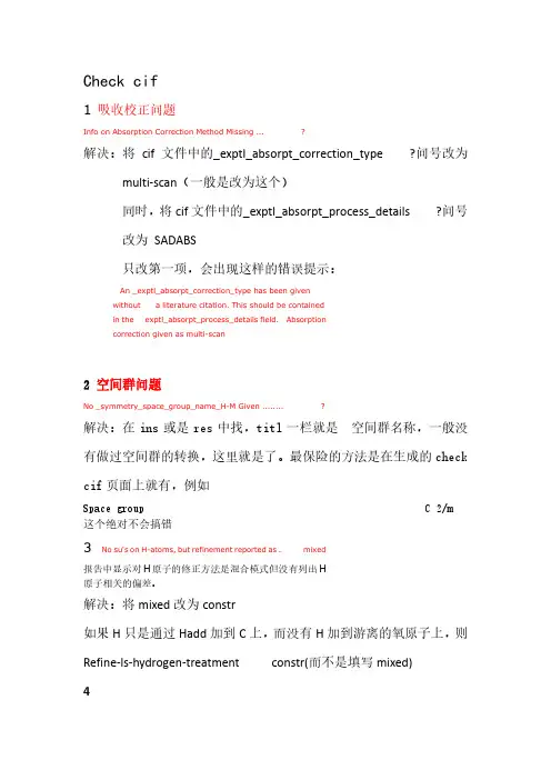
Check cif1 吸收校正问题Info on Absorption Correction Method Missing ... ?解决:将cif文件中的_exptl_absorpt_correction_type ?问号改为multi-scan(一般是改为这个)同时,将cif文件中的_exptl_absorpt_process_details ?问号改为SADABS只改第一项,会出现这样的错误提示:An _exptl_absorpt_correction_type has been givenwithout a literature citation. This should be containedin the exptl_absorpt_process_details field. Absorptioncorrection given as multi-scan2 空间群问题No _symmetry_space_group_name_H-M Given ........ ?解决:在ins或是res中找,titl一栏就是空间群名称,一般没有做过空间群的转换,这里就是了。
最保险的方法是在生成的check cif页面上就有,例如Space group C 2/m 这个绝对不会搞错3 No su's on H-atoms, but refinement reported as . mixed报告中显示对H原子的修正方法是混合模式但没有列出H原子相关的偏差。
解决:将mixed改为constr如果H只是通过Hadd加到C上,而没有H加到游离的氧原子上,则Refine-ls-hydrogen-treatment constr(而不是填写mixed)4Ratio of Maximum / Minimum Residual Density .... 2.72正负残留峰的双值应该接近1,出现这样的错误表明精修不到位,可能还有残余峰。

5G NSA 网络scg-failure 原因掉话问题分析XX目录摘要 (3)一、NSA 5G 网络掉话场景 (4)1.1eNodeB 触发的释放 (4)1.2gNodeB 触发的释放 (5)二、NSA 5G 网络掉话分析 (6)2.1核心网发起释放 (7)2.24G 侧重建或掉话 (8)2.3UE 侧上报SCGFailure 异常释放 (10)三、SCGFailure 应用举例 (11)3.1案例RandomAccessProblem: RAR 波束信号弱RAR 失败,NR 小区添加失败 (11)3.2案例 rlc-MaxNumRetx:SRS 周期配置过小引起RLC 达到最大重传掉话 (13)3.3案例 rlc-MaxNumRetx:终端未开性能模式导致RLC 达到最大重传掉话 (14)3.4案例 scg-changefailure:NR 小区频繁故障导致辅站变更过程中UE 随机接入失败 (16)3.5案例 scg-changefailure:4-5 邻区漏配导致NR 掉话 (18)3.6案例 SynchReconfigFailureSCG:外部小区配置错误导致NR 接入失败 (19)四、经验总结 (21)摘要NSA 组网的一大特点是可以基于现有的 LTE 核心网实现 5G 快速部署,是在5G 初期运营商大规模投资后收益不确定的情况下,既达到快速部署 5G 网络又降低5G 投资的“一石二鸟”过渡方案,所以 5G 商用初期,运营商都选择了 NSA 组网。
但 NSA 网络优化较为复杂,需要 4G、5G 两张网络同步进行,特别发生 5G 用户掉话,如何快速定位问题则非常重要。
本文结合 NSA 网络架构原理和掉话信令流程,分别从 eNodeB 和 gNodeB 两侧进行掉话场景分类,而 4G 侧上报的 ScgFailure 则是主要分析掉话的切入口。
本文通过UE 上报Scg-Failure 问题原因值,列举了常见四大类:“SynchReconfigFailureSCG”、“RandomAccessProblem”、“scg-changefailure”、“rlc-MaxNumRetx” ,并依次进行具体案例举例剖析,总结了一套排查优化手段,形成形成了一套行之有效的处理流程,为 NSA 掉话问题的解决提供了有力指引,为后期 NSA 网络优化提供了借鉴。
升级bios出现error15解决教程升级BIOS出现Error 15解决教程BIOS(Basic Input/Output System)是计算机系统中的一个重要组成部分,它负责启动计算机并管理硬件设备。
随着技术的不断发展,BIOS也需要不断升级以适应新的硬件和软件需求。
然而,在升级BIOS的过程中,有时会遇到Error 15的错误提示,这可能会导致计算机无法正常启动。
本文将为大家介绍一些解决Error 15的方法。
首先,我们需要了解Error 15的含义。
Error 15通常表示BIOS固件无法找到可引导的设备。
这可能是由于BIOS升级过程中出现了错误,或者是升级后的BIOS与硬件设备不兼容所致。
解决Error 15的方法有以下几种:1. 检查硬件连接:首先,我们需要检查计算机的硬件连接是否正确。
确保硬盘、光驱等设备与主板连接良好,没有松动或接触不良的情况。
如果发现问题,可以重新插拔连接线,确保连接稳固。
2. 恢复默认设置:有时,BIOS升级后的设置可能与原来的设置不兼容,导致Error 15的出现。
在计算机启动时,按下Del或F2键进入BIOS设置界面,找到“Load Default Settings”(恢复默认设置)选项,选择并保存。
然后重启计算机,看是否能够解决问题。
3. 刷新BIOS固件:如果以上方法无效,我们可以尝试刷新BIOS固件。
首先,需要下载适用于您的主板型号的最新BIOS固件文件,并将其保存到U盘或其他可启动的存储设备中。
然后,将存储设备插入计算机,并按下特定的按键(通常是Del或F2)进入BIOS设置界面。
在BIOS设置界面中,找到“BIOS Update”(BIOS升级)选项,选择从存储设备中加载固件文件,并按照提示完成刷新过程。
刷新BIOS固件可能需要一些时间,请耐心等待。
完成后,重启计算机,看是否能够解决Error 15的问题。
4. 寻求专业帮助:如果以上方法仍然无法解决Error 15的问题,我们建议寻求专业的计算机维修师傅的帮助。
NSA VoLTE 掉话原因分析处理XX分公司目录1 概述 (3)1.1 版本信息 (3)1.2网络拓扑图 (3)2 NSA VoLTE 掉话问题 (3)2.1问题背景 (3)2.2问题分析 (4)2.3解决措施 (4)2.4.4现场验证 (5)3 整体测试验证情况 (6)3.14G数据业务验证 (6)3.1.1用户感知指标:(上行优良比)(≥5M bp s) (6)2.1.2用户感知指标:(下行优良比)(≥12M bp s) (6)3.1.3切换指标:切换成功率 (6)3.1.4切换失败原因分析 (7)3.2V oL T E验证 (7)3.2.1覆盖率 (7)3.2.2接通率 (8)3.2.3掉话率 (8)3.2.4M O S优良比(≥3.5比例) (8)3.2.5呼叫建立时延(秒) (8)3.2.6切换成功率,切换失败原因分析 (8)3.3关键KP I (8)3.3.1接通率 (8)3.3.2切换成功率 (9)3.3.3V o l t e接通率 (9)4 总结 (10)1概述1.1版本信息项目相关信息升级时间2019 年 4 月 15 日 0:00~4:00eNodeB BTS3900 V100R015C10SPC100测试工具(终端跟踪工具) 4G:鼎利5G:Mate 20 X1.2网络拓扑图2NSA VoLTE 掉话问题2.1 问题背景NSA 用户做 VoLTE,由 NSA 锚点站切换到 17B LTE only 存量站点失败。
测试手机在R15协议版本基站驻留(已添加N R),拨打V o LTE 电话,向R12.1协议版本基站移动,触发切换,切换后 VoLTE 会发生掉话。
2.2 问题分析NSA 终端在 NSA 区域下使用 NR PDCP,而17B 及之前的 LTE 版本不支持 R15 协议,无法识别N R P D C P,所以当17B基站接收到19B基站发出的切换准备消息时,因为协议不兼容,不能识别切换准备消息中的 NR P DCP,最终导致切换准备失败。
fcc par 15标准FCC Part 15标准是美国联邦通信委员会(Federal Communications Commission,简称FCC)制定的无线电设备的无线电频率电磁兼容性(EMC)标准。
它规定了无线电设备的电磁辐射和抗扰度的限制要求,以确保无线电设备不会对其他设备或无线电服务造成不良影响。
FCC Part 15标准包括两种类别:Part 15 Class A和Part 15 Class B。
Class A适用于商业、工业或业务用途的设备,而Class B适用于家庭或个人使用的设备。
这些标准适用于所有使用电磁波频率的设备,包括无线电发射器、计算机设备、数字设备、电视接收器、监视器等等。
FCC Part 15标准还包含了多个子标准,例如Part 15.107、Part 15.109、Part 15.207、Part 15.209等等,每个子标准都包含了特定的测试要求和限制。
具体来说,FCC Part 15的几个子部分分别是:Subpart A:这是FCC Part 15的概述性规范,包括了一般的规则和定义,旨在确保设备的电磁辐射不会产生干扰其他电子设备或无线电通信系统。
Subpart B:这是关于计算机设备的规范,定义了计算机设备的电磁辐射限值、测试方法和标签要求。
它规定了设备应该符合的辐射限制,以保证设备在正常操作时不会影响其他设备的功能。
Subpart C:这是关于电视接收设备的规范,规定了这类设备所产生的无线电干扰限值,以确保电视接收器能够正常接收广播信号而不受其他设备的干扰。
Subpart D:这是关于无线电辐射检测仪器的规范,规定了无线电测量设备的技术要求和测试程序,确保其准确地测量和检测电磁辐射。
Subpart E:这是关于低功率设备的规范,用于管理使用低功率无线电频谱的设备,如无线耳机、无线键盘等。
它规定了这些设备应满足的频谱使用条件和技术要求,以避免干扰其他设备或频段。
系统消息解析1 MIB (Master Information Block)解析MIB主要包含系统带宽、PHICH配置信息、系统帧号。
(下图为实测信令)➢DL_Bandwidth系统带宽,范围enumerate(1.4M(6RB,0),3M(15RB,1),5M(25RB,2),10M(50RB,3),15M(75RB,4),20M(100RB,5)),上图为n100,对应的系统带宽为20M(100RB,带宽索引号为5)。
➢Phich_Duration当该参数设置为normal时,PDCCH占用的OFDM符号数可以自适应调整;当该参数设置为extended时,若带宽为1.4M,则PDCCH占用的OFDM符号数可以取3或4,对于其他系统带宽下,PDCCH占用的符号数只能为3。
➢PHICH-Resource该参数用于计算小区PHICH信道的资源;➢SystemFrameNumber系统帧号。
系统帧号,用于UE获取系统时钟。
实际SFN位长为10bit,也就是取值从0-1023循环。
在PBCH的MIB广播中只广播前8位,剩下的两位根据该帧在PBCH 40ms周期窗口的位置确定,第一个10ms帧为00,第二帧为01,第三帧为10,第四帧为11。
PBCH 的40ms窗口手机可以通过盲检确定。
➢Spare:预留的,暂时未用2 SIB1 (System Information Block Type1)解析SIB1上主要传输评估UE能否接入小区的相关信息及其他系统消息的调度信息。
主要包括4部分:➢小区接入相关信息(cell Access Related Info)➢小区选择信息(cell Selection Info)➢调度信息(scheduling Info List)➢TDD配置信息(tdd-Config)SIB1消息解析(UE侧):RRC-MSG..msg....struBCCH-DL-SCH-Message......struBCCH-DL-SCH-Message........message..........c1............systemInformationBlockType1..............cellAccessRelatedInfo//小区接入相关信息................plmn-IdentityList//PLMN标识列表..................PLMN-IdentityInfo....................plmn-Identity ......................mcc//460 ........................MCC-MNC-Digit:0x4 (4) ........................MCC-MNC-Digit:0x6 (6) ........................MCC-MNC-Digit:0x0 (0) ......................mnc//00 ........................MCC-MNC-Digit:0x0 (0) ........................MCC-MNC-Digit:0x0 (0) ....................cellReservedForOperatorUse:notReserved (1) ................trackingAreaCode:11100(890C)//TAC跟踪区(890C)为16进制数,转换成十进制为35084,查TAC在该消息中可以查到,此条信元重要。
S720 SPORTRADIO CONTROL AIRPLANEQUICK START GUIDE OMP S720 航模运动飞机快速上手指南Packing List 开箱内含:①. Fuselage 机身 ②. Left Wing 左机翼 ③. Right Wing 右机翼④/⑤. Horizontal Stabilizers 左尾翼/右尾翼 ⑥. Controller 遥控器⑦. Battery & Charger 充电器、电池 ⑧. Landing Gear 起落架⑨. Manual & Screw Driver螺丝刀、说明书INSTALLATION 组装飞机1. Gear Installation 安装起落架和尾轮:Insert the left/right landing gear into the socket under the front of the fuselage.Ensure the landing gears are locked firmly with the fuselage.Insert the rear gear into the tail wheel socket below the rear of the fuselage. Ensure the rear gear is locked firmly with the fuselage.2. Wing Set Installation 安装机翼:Insert the locking hooks of the wing set through the square holes of the fuselage until a "click" sound. Ensure the aileron levels on the fuselage are fully insert into the aileron of the wings. Be sure to verify line up of round pin of wing as well.CAUTION 注意:Ensure the wings are inserted securly, as well as the aileronsalign withthe wings. Improper installation may cause crash due to rollingmovement out of control.将左/右起落架分别插入机身前部下方的起落架插座,用力插到底,确保左/右起落架与机身内的插座锁扣在一起。
WarningThis device complies with Part 15 of the FCC Rules. Operation is subject to the following two conditions: (1) this device may not cause harmful interference, and (2) this device must accept any interference received, including interference that may cause undesired operation.Changes or modifications not expressly approved by the party responsible for compliance could void the user's authority to operate the equipment.Note: This equipment has been tested and found to comply with the limits for a Class B digital device, pursuant to Part 15 of the FCC Rules. These limits are designed to provide reasonable protection against harmful interference in a residential installation. This equipment generates, uses and can radiate radio frequency energy and, if not installed and used in accordance with the instructions, may cause harmful interference to radiocommunications. However, there is no guarantee that interference will not occur in a particular installation. If this equipment does cause harmful interference to radio or television reception, which can be determined by turning the equipment off and on, the user is encouraged to try to correct the interference by one or more of the following measures:—Reorient or relocate the receiving antenna.—Increase the separation between the equipment and receiver.—Connect the equipment into an outlet on a circuit different from that to which the receiver is connected.—Consult the dealer or an experienced radio/TV technician for help.NOTE: This device and its antenna(s) must not be co-located or operation in conjunction with any other antenna or transmitterPair the Gateway with APPSelect [Gateway ]3Activate the APPPress “ ”21。
1.RE_TEST(Radiated emission limits)
在361.8,723.6MHz
2.依据PCB布局,芯片手册,天线原理追踪原因如下:
(1)电源部分;
(2)芯片(ADM2582E)PCB布局;
3.测试验证及解决方案
(1)验证是否是AP辐射超限:
抽样1.测试数据如下:
抽样2.测试数据如下:
抽样3.测试数据如下:
测试过程中,AP烧录出厂程序,接通电源利用天线进行测试无线接收,可以测试到抽样的三个AP在362MHZ附近产生了杂散信号,
断开电源即AP不工作时测试不到上述强度的杂散信号。
(2)
①电源部分影响及解决方案
直流48V供电测试 AC-DC_48V测试
上述测试分别采用直流和AC-DC_48V电源分别给AP供电,用频谱仪外接天线,在AP电路板周围逐步移动,频谱仪设置参数不变情况下,AP没有辐射杂散信号。
直流48通过经N1给AP供电测试 AC-DC_48V通过N1给AP供电测试直流48V及AC-DC_48V两种方式都给N1供电,再经网线给AP供电,测试过程中都能在362MHz附件收到杂散信号。
②芯片周围布局影响验证及解决方案
排除电源(用直流电供电)影响基础上,验证芯片布局影响:用频谱仪外接天线,在AP电路板周围逐步移动,频谱仪设置参数不变情况下,在芯片ADM2582布局区域,接收到杂散信号,和FCC-part15测试到频点一致。
@362MHZ频点杂散信号
在芯片ADM2582区域进行屏蔽处理后再进行接收测试,取样的两块儿AP已经得到改善即杂散已经被衰减掉。
测试数据如下:
芯片屏蔽后测试数据
该方法在找EMI 源头非常有效,这一点在后来整改中也验证了这一推断。
解决方法自然也有多种途径。
2015.12。