Beckhoff测量模块
- 格式:pdf
- 大小:14.38 MB
- 文档页数:9
元件介绍倍福模块:控制柜现在所用到的模块主要是:CPU 、DI 、AI 、DO 端子及总线端子。
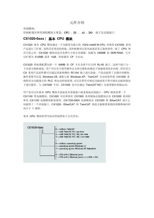
CX1020-0xxx | 基本CPU 模块CX1020 基本CPU 模块通过一个功能更为强大的1GHz Intel® M CPU 对现有CX1000 系列产品进行了扩展。
虽然具有更高的性能,该控制器却无需风扇或者其它旋转部件。
除了CPU 和芯片组之外,CX1020 模块还包含各种尺寸的主存储器,标配为256MB 的DDR RAM,它可以扩展为512MB 或者1GB。
控制器从CF 卡启动。
CX1020 的标准配置包括一个64MB 的CF 卡以及两个以太网RJ 45 接口。
这两个接口与一个内部交换机相连,用户可以在不使用额外以太网交换机的情况下创建线型拓扑结构。
所有其它CX 系列产品组件都可以通过设备两侧的PC104 接口进行连接。
产品还提供了无源冷却模块。
操作系统可以是Windows CE 或嵌入版Windows XP。
TwinCAT 自动化软件把CX1020 系统转化为功能强大的PLC 和运动控制系统,可以在带有可视化功能或者不带可视化功能的情况下进行操作。
与CX1000 不同,CX1020 也可以通过TwinCAT NC I 完成带插补的轴运动。
用户也可以在基本CPU 模块中添加更多系统接口或者现场总线接口。
CPU 模块需要一个CX1100 型电源模块。
CX1020 可以和所有CX1500 系列现场总线模块以及CX1000 系列的所有CX1100 电源模块配套使用。
CX1100-0004 电源模块在CX1020 和EtherCAT 端子之间提供了一个直接接口。
CX1020,EtherCAT 和TwinCAT 的组合能够使系统的周期和响应时间小于 1 微秒。
基本CPU 模块的型号标识符按照如下方式导出:CX1020-0000处理器Intel® Celeron® M ULV,时钟频率 1 GHz内部闪存64 MB CF卡内部主存256 MB DDR RAM (可以扩展到512MB,1G 字节)接口 2 x RJ 45 (内部交换机)诊断用LED 显示1×电源诊断,2×局域网连接/功能诊断,1×WD 诊断,1×闪存访问诊断扩展插槽1×I+II 型CF 卡插槽,带有弹出装置时钟由由内部电池支持的时钟,用于时间和日期操作系统微软公司的Windows CE 或者嵌入版Windows XP控制软件TwinCAT PLC 实时系统,NC PTP 实时系统,NC I 实时系统系统总线16 位ISA(标准PC104 接口)电源通过系统总线(通过CX1100 电源模块)最大功耗11W(包括CX1000-N00x 系统接口)尺寸(W x H x D) 76 mm x 100 mm x 91 mm近似重量550 g工作温度0 °C ... +50°C储藏温度-25 °C ... +85 °C相对湿度95%,无冷凝抗振动/抗冲击性能符合EN 60068-2-6/EN 60068-2-27/29 标准符合EN 61000-6-2(ESD,脉冲)EN 61000-6-4 标准抗电磁及瞬时脉冲干扰/静电放电防护等级IP 20DI端子:EL1004:EL1004 数字量输入端子从现场级获得二进制控制信号,并把数据以电隔离的信号形式传输到更高层的自动化单元。
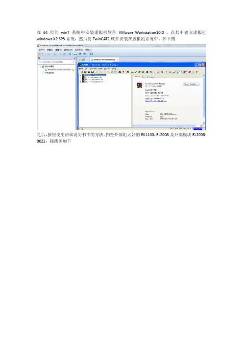
在64位的win7系统中安装虚拟机软件VMware Workstation10.0 ,在其中建立虚拟机windows XP SP3系统,然后将TwinCAT2软件安装在虚拟机系统中。
如下图
之后,按照使用倍福说明书中的方法,扫查外部组太好的EK1100,EL2008及外部模块EL2008-0022,接线图如下
要保证正确的实物接线,上电后,会有相应的指示灯亮起或亮闪,具体看资料,不再赘述。
接下来就是在打开的TwinCAT2中扫查IO模块了,右击I/O Devices 然后选择Scan Devices
然后会出现下面的错误,扫查出是Ethernet设备
我们扫查的是EtherCAT的设备,应该出现的是下面结果,扫查出的是EtherCAT设备
如何解决??
1、首先确定外部接线正确,网线插好,保证PC和设备正常连接
2、安装TwinCAT的驱动,安装好后,点showbindings,会显示两个驱动
(已经安装好的驱动)
3、在网络和共享中关闭虚拟机网络连接,
4、虚拟机中设置“桥接模式”,(桥接模式是用主机本身网卡与外界通讯)
然后就可以正常扫查了。
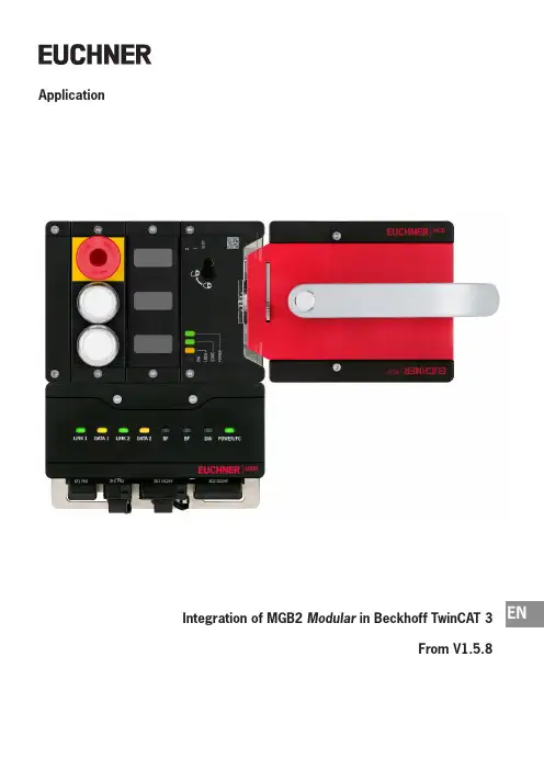
ENApplicationIntegration of MGB2 Modular in Beckhoff TwinCAT 3From V1.5.8Application MGB2Integration of MGB2 Modular in Beckhoff TwinCAT 32(Application) AP000236-01-02/21Contents1.About this document (4)1.1. Version ..........................................................................................................................................41.2. Scope ............................................................................................................................................41.3. Target group ..................................................................................................................................41.4.Supplementary documents (4)1.5. Notice (4)2. Components/modules used (5)2.1. EUCHNER (5)2.1.1. Items included in the MGB2 Modular set (5)2.2. Others ...........................................................................................................................................52.3. Software . (6)3. Functional description ...........................................................................................64.Overview of the communication data (7)4.1. Input ..............................................................................................................................................74.2. Output . (7)5. Installing the GSD file ............................................................................................86. Setting the control system parameters ..................................................................87.TwinSAFE and PROFIsafe hardware addressing (9)7.1. TwinSAFE .......................................................................................................................................97.2. PROFIsafe .. (9)8. Configuration of the MBM and the I/O peripherals (10)8.1. Adding the I/O devices in the project ..............................................................................................108.2.Setting the MGB2 Modular parameters .........................................................................................148.2.1. PROFINET .....................................................................................................................148.2.2. PROFIsafe ....................................................................................................................168.3.Assigning PROFINET device name to the bus module MBM (17)9. PLC program creation (19)9.1. Structure of the connection for PROFINET I/O configuration .............................................................199.2. Structure for readability of the inputs/outputs .................................................................................209.3.Function block FB_EUCHNER_MGB2modular ........................................................................229.3.1. Copying the CPU input structure to the MGB2 Modular structure .....................................229.3.2. Copying the MGB2 Modular output structure to the CPU structure ...................................239.4. PROFINET program .......................................................................................................................239.5. EtherCAT program ........................................................................................................................249.6. Main program MAIN ............................................................................................................249.7.Linking the program variables (24)Application MGB2Integration of MGB2 Modular in Beckhoff TwinCAT 39.8. Transferring program to the PLC (27)9.9. Observing the non-safe variables (27)10. Configuration of TwinSAFE – ProfiSAFE (28)11. Creating the safety program (35)11.1. Example of a safety program (35)11.2. Transferring safety program (37)12. Important note – please observe carefully! (38)3 AP000236-01-02/21 (Application)Application MGB2Integration of MGB2 Modular in Beckhoff TwinCAT 34(Application) AP000236-01-02/211. About this document1.1.Version1.2. Scope This document is used for integration and configuration of MGB2 Modular using BECKHOFF TwinCAT 3.1.3.Target groupDesign engineers and installation planners for safety systems on machines, as well as setup and servicing staff possessing special expertise in handling safety components as well as expertise in the installation, setup, programming and diagnostics of programmable logic controllers (PLCs) and bus systems.1.4. Supplementary documentsThe overall documentation for this application consists of the following documents:1.5. NoticeThis application is based on the MGB2 Modular operating instructions. Please refer to the operating instructions for technical details and other information.5AP000236-01-02/21 (Application)Application MGB2Integration of MGB2 Modular in Beckhoff TwinCAT 3EN2. Components/modules used2.1.EUCHNER2.1.1. Items included in the MGB2 Modular setTip: More information and downloads about the aforementioned EUCHNER products can be found at . Simply enter the order number in the search box.2.2. OthersApplication MGB2Integration of MGB2 Modular in Beckhoff TwinCAT 36(Application) AP000236-01-02/212.3.Software3. Functional descriptionThe MGB2-L1HB-PN-.. is a guard locking device in accordance with EN ISO 14119 according to the closed-circuit current principle, the MGB2-L2HB-PN-.. is a guard locking device in accordance with EN ISO 14119 according to the open-circuit current principle. In this example, all safety functions are processed via the PROFIsafe protocol. The MGB2 Modular is con-nected to a CX9020-0110-M930 from BECKHOFF.7AP000236-01-02/21 (Application)Application MGB2Integration of MGB2 Modular in Beckhoff TwinCAT 3EN4. Overview of the communication data4.1.Input4.2.OutputTip: The individual abbreviations are explained in the operating instructionsApplication MGB2Integration of MGB2 Modular in Beckhoff TwinCAT 38(Application) AP000236-01-02/215. Installing the GSD fileYou will require the corresponding GSD file in GSDML format to integrate the MGB2 Modular into the TwinCAT 3 hardware configuration:ÌGSDML-V2.33-EUCHNER-MBM_2512512_T14-YYYYMMDD.xmlYou will find the GSD files in the download area at . Always use the latest GSD file.Unzip the content of the GSDML file into the following directory: ÌC:/TwinCAT/3.1/Config/Io/ProfinetFigure 1:Content of the ZIP fileFigure 2: GSDML file path for TwinCAT 36. Setting the control system parametersSpecify the cycle time for the PlcTask. The value 2 must be set for a PROFINET application.Figure 3: PlcTask parameters9AP000236-01-02/21 (Application)Application MGB2Integration of MGB2 Modular in Beckhoff TwinCAT 3EN7. TwinSAFE and PROFIsafe hardware addressing7.1.TwinSAFEThe TwinSAFE address must be set for the TwinSAFE logic module EL6910 and the fail-safe output module EL2904. It isset using the DIP switches on the left side of the TwinSAFE terminals.7.2. PROFIsafeThe PROFIsafe address (F_Dest_Add) is set on the bus module MBM using the DIP switches. The PROFIsafe address must be set to the value configured.The DIP switch setting is as follows from the F_Dest_Add 12 as configured in the hardware configurator:Table 1: DIP switch settingsApplication MGB2Integration of MGB2 Modular in Beckhoff TwinCAT 310(Application) AP000236-01-02/218. Configuration of the MBM and the I/O peripherals8.1.Adding the I/O devices in the projectAdd the devices as follows:1. Open Solution Explorer , click I/O , then right-click Devices and select Scan from the context-sensitive menu.2.Select the PROFINET and EtherCAT controllers.Figure 4: Solution Explorer Figure 5: Selecting the controllers3. Activate the search for PROFINET devices in the following pop-up window, Scan for BoxesEN4. Compare the MAC address on the type label with the MAC address of the devices available in the network, and add theMBM to PROFINET with Add Devices.Figure 6: Adding MBM5. Then scan the real configuration. After completion of the scanning process, the hardware configuration appears asshown in Figure 7.Figure 7: Structure of the modules usedEN6. Complete the configuration of the MGB2 Modular with the modules used in the example. Begin by right-clicking on Term 2(EmptySlot), and use Insert New Item... to insert the module PROFIsafe 2 Bytes , PROFIsafe 4 Bytes orPROFIsafe 8 Bytes.Figure 8: Adding PROFIsafe modules Figure 9: Adding additional submodules7. Add modules and submodules to MGB2 Modularcorresponding to your layout.Figure 10: Hardware layout, MGB2 Modularset8.2. Setting the MGB2 Modular parameters8.2.1. PROFINETThe following PROFINET parameters must be set:ÌDevice name/station name (factory setting from GSD file): [euchner-mbm].ÌIP address: fixedFigure 11: PROFINET parametersFigure 12: PROFINET real time settingsÌIO cycle real time settingsUpdate time: Calculate update time automatically (recommended)Watchdog time: accepted update cycles without IO data: 3 (recommended)EN8.2.2. PROFIsafeThe following PROFIsafe parameters must be set:ÌF_Dest_Add (PROFIsafe address): 12 (TwinCAT 3 sets the default PROFIsafe address; addressing can be changed manu-ally).ÌF_WD_Time (time during which the control system expects a response from the PROFIsafe device): 600 ms. Factory setting from GSD file: [600 ms].Figure 13: PROFIsafe parameters8.3. Assigning PROFINET device name to the bus module MBM1. To assign the name to MGB2 Modular via TwinCAT, right-click the PROFINET controller and then select Scan.EN2. Select the MBM from the list. Enter the station name and assign it using Set Stationname. Additionally assign the IPaddress with Set IP configuration.Figure 15: Assigning device namesEN9. PLC program creationThe following program structure is used for PROFINET communication (non-safe communication):9.1.Structure of the connection for PROFINET I/O configurationThe input/output structure of the MGB2 Modular sets is mapped equivalently to the communication data in the ST_MGB-2modular_PN_IO structure.Figure 16:ST_MGB2modular_PN_IO9.2. Structure for readability of the inputs/outputsThe inputs and outputs of the MGB2 Modular are prepared for better readability in the ST_MGB2modular_IO structure. The data structure shown on the data sheet [chapter 4] is used as the template for this.Figure 17: Structure of inputsFigure 18: Structure of outputsEN9.3. Function block FB_EUCHNER_MGB2modularThe structure of the variables is copied to the structure of the inputs/outputs in the function block FB_EUCHNER_MGB2modular.9.3.1. Copying the CPU input structure to the MGB2 Modular structureFigure 19: Copying the CPU input structureEN9.3.2. Copying the MGB2 Modularoutput structure to the CPU structureFigure 20: Copying the MGB2 Modular output structures9.4. PROFINET programThe variable structure for PROFINET diagnostics is created in the PRG_ProfiNET program. Additionally, an instance of the function block FB_EUCHNER_MGB2modularis called.Figure 21: PRG_ProfiNET program9.5. EtherCAT programThe EtherCAT diagnosis can be read with the PRG_EtherCAT program.Figure 22: PRG_EtherCAT9.6. Main program MAINThe main program MAIN is used to call the subprograms PRG_ProfiNET and PRG_EtherCAT.Figure 23: MAIN program9.7. Linking the program variablesLinking establishes a connection between the MGB2 Modular input and output variables and the program structure. The CPU program must first be compiled for this purpose. The program can be compiled with Build Solution (Ctrl+Shift+B). You can then find the variables to be linked under the created CPU instance.1. Double-click the variable to be linkedEN2. Link the variables withLinked to...3. Select the input area to be linked, and complete with OKAll created variables must be linked as described in this example.Figure 24: Variables to be linked9.8. Transferring program to the PLCTransfer the program to the control system by clicking Activate configuration , and set the control system to Run mode.9.9. Observing the non-safe variablesThe inputs and outputs of the MGB2 Modular can be viewed using the block interface of the PRG_ProfiNET program. Go.online by clicking LoginEN10. Configuration of TwinSAFE – ProfiSAFEThe following chapter describes the configuration the TwinSAFE output and the ProfiSAFE connection of the MGB2 Modular.1. Set the PRG_TwinSAFE program as the PLC program.2. PRG_TwinSAFE variable declaration: The xTwinSAFE_Run and xTwinSAFE_Ack variables are required as transfer variablesto the safe control system.Figure 26: PRG_TwinSAFE variable declaration3. The submodule’s S3 button is used to implement acknowledgment of the safe control system in the event of an error.For this purpose, assign the variables as shown in Figure 27.Figure 27: Acknowledgment using the submodule’s button.4. Call PRG_TwinSAFE in the main programFigure 28: MAIN (PRG)EN5.Add the safety projectFigure 29:Adding safety project6. Create the target system: the Beckhoff terminal EL6910 must be selected as the target system. The terminal functionsas the PROFIsafe controller as well. The safe address is also entered. Map Serial Number and Map Project CRC can be activated for expanded diagnostics.Figure 30: Target system7. In the next step, the variables from PRG_TwinSAFE are assigned to the created Alias Devices ErrorAcknowledgementand Run. Open the properties by double-clicking the variable.Figure 31: Alias ErrorAcknowledgement Figure 32: Alias Run31AP000236-01-02/21 (Application)Application MGB2Integration of MGB2 Modular in Beckhoff TwinCAT 3EN8.Add the PROFIsafe connection:Figure 33:Adding PROFIsafe connectionApplication MGB2Integration of MGB2 Modular in Beckhoff TwinCAT 332(Application) AP000236-01-02/219. PROFIsafe settings of the MGB2 Modular : The assignment (mapping) to the slot PROFIsafe 2 Bytes , the safe address(physical DIP switch setting) and the F_WD_Time (600 ms from GSDML factory setting) must be set.Figure 34: PROFIsafe settings33AP000236-01-02/21 (Application)Application MGB2Integration of MGB2 Modular in Beckhoff TwinCAT 3EN10.Add the TwinSAFE connection to terminal EL2904.Figure 35: Adding TwinSAFE connection11.Set terminal parameters: link to physical device and FSoE address (Fail Safe over EtherCAT; physical DIP switch setting).Application MGB2Integration of MGB2 Modular in Beckhoff TwinCAT 334(Application) AP000236-01-02/21Figure 36: TwinSAFE settings EL290435AP000236-01-02/21 (Application)Application MGB2Integration of MGB2 Modular in Beckhoff TwinCAT 3EN11. Creating the safety programThe safety engineering application is implemented in the sal (sal: Safety Application Language) worksheet belonging to theTwinSAFE group. It represents only an example of an application.11.1. Example of a safety programIn the following example, the safe output of terminal EL2904 (channel 1) is controlled by the bit LM_FI_UK. The conditionsfor the bit LM_FI_UK are met if the door is closed, the bolt tongue is in the locking module and guard locking is active.Figure 37: Example of a safety programApplication MGB2Integration of MGB2 Modular in Beckhoff TwinCAT 336(Application) AP000236-01-02/21The variables are assigned for the TwinSAFE group (mapping) after addition of the blocks. Mapping must be performed for the variables xLM_FI_UK , xFO_1, Err Ack and Run/Stop.Figure 38: Mapping xLM_FI_UK Figure 39: Mapping xFO_137AP000236-01-02/21 (Application)Application MGB2Integration of MGB2 Modular in Beckhoff TwinCAT 3ENFigure 40: Mapping Err Ack Figure 41: Mapping Run11.2. Transferring safety programSave the overall project with Save Alland transfer the configuration with Activate Configuration. Subsequentlycheckand transfer the TwinSAFE program to the control system. The user name [default: Administrator], the password [default: TwinSAFE] and the serial number of the target system will be required for transfer.Application MGB2Integration of MGB2 Modular in Beckhoff TwinCAT 338(Application) AP000236-01-02/2112. Important note – please observe carefully!This document is intended for a design engineer who possesses the requisite knowledge in safety engineering and knows the applicable standards, e.g. through training for qualification as a safety engineer. Only with the appropriate qualification is it possible to integrate the example provided into a complete safety chain.The example represents only part of a complete safety chain and does not fulfill any safety function on its own. In order to fulfill a safety function, the energy switch-off function for the danger zone and the software must also be considered in the safety evaluation, for example.The applications provided are only examples for solving certain safety tasks for protecting safety doors. The examples cannot be comprehensive due to the application-dependent and individual protection goals within a machine/installation.If questions concerning this example remain open, please contact us directly.According to the Machinery Directive 2006/42/EC, the design engineer of a machine or installation has the obligation to perform a risk assessment and take measures to reduce the risk. While doing this, the engineer must comply with the appli-cable national and international safety standards. Standards generally represent the current state-of-the-art. Therefore, the design engineer should continuously inform himself about changes in the standards and adapt his considerations to them. Relevant standards for functional safety include EN ISO 13849 and EN 62061. This application must be regarded only as assistance for the considerations about safety measures.The design engineer of a machine/installation has the obligation to assess the safety technology himself. The examples must not be used for an assessment, because only a small excerpt of a complete safety function was considered in terms of safety engineering here.In order to be able to use the safety switch applications correctly on safety doors, it is indispensable to observe the stan-dards EN ISO 13849-1, EN ISO 14119 and all relevant C-standards for the respective machine type. Under no circumstances does this document replace the engineer’s own risk assessment, and it cannot serve as the basis for a fault assessment.In particular in relation to a fault exclusion, it must be noted that a fault can be excluded only by the machine's or installation's design engineer and this action requires justification. A general fault exclusion is not possible. More information about fault exclusion can be found in EN ISO 13849-2.Changes to products or within assemblies from third-party suppliers used in this example can lead to the function no longer being ensured or the safety assessment having to be adapted. In any event, the information in the operating instructions on the part of EUCHNER, as well as on the part of third-party suppliers, must be used as the basis before this application is integrated into an overall safety function. If contradictions should arise between the operating instructions and this doc-ument, please contact us directly.Use of brand names and company namesAll brand names and company names stated are the property of the related manufacturer. They are used only for the clear identification of compatible peripheral devices and operating environments in relation to our products.Application MGB2Integration of MGB2 Modular in Beckhoff TwinCAT 339 AP000236-01-02/21 (Application)EUCHNER GmbH + Co. KGKohlhammerstraße 1670771 Leinfelden-EchterdingenGermany***************Edition:AP000236-01-02/21Title:Application MGB2Integration of MGB2 Modular in Beckhoff TwinCAT 3Copyright:© EUCHNER GmbH + Co. KG, 02/2021Subject to technical modifications; no responsibility is accept-ed for the accuracy of this information.。


塔基模块
模块供电EL9210
安全模块EL6900
本组为输出4回路
ETHERCAT通讯模块EK1110
数字量输入
E1104
通过以太网通讯,
实现模块的拓展,
用于一组模块和另
一组模块串联
输入2的通道有信号
时指示绿灯亮
输入4的通道有信号
时指示绿灯亮
数字输入1、2、3、4通道
为信号的反馈接收点,采
集到的数字信息将由此通
道提交给PLC
数字量输出EL2004
输出2正常输出24V
时,指示绿灯亮
输入4回路
模拟量输入EL3122
ETERCAT 通讯模块EK1521
CANOPE 通讯模块EL6751
通讯正常
CPU
状态错误
机舱模块
数字量输入EL1104
数字量输出EL2004
系统端子模块EL9410
安全模块EL1904
模拟量输入EL3122
模拟量输入EL3204
模拟量输入EL3062
EL4002
系统端子模块EL9410
位置测量端子模块EL5001
位置测量模块EL5151
EL6731。
BECKHOFF产品简明操作指南_彩色1.BECKHOFF控制器操作指南(a)上电和初始化控制器:将控制器连接到电源,并确保所有必需的电缆正确连接。
然后,按下电源按钮启动控制器。
在初始化过程完成后,可以通过配置软件进一步配置控制器。
(b)配置IO接口:BECKHOFF控制器通常具有多个IO接口,用于连接不同类型的传感器和执行器。
可以使用配置软件为每个IO接口分配正确的功能,并设置相应的参数。
(c) 编程控制器:使用BECKHOFF提供的编程软件进行控制器编程。
BECKHOFF支持多种编程语言和开发环境,如TwinCAT和CODESYS。
根据您的需求选择合适的工具,并使用其提供的函数和API进行编程。
2.BECKHOFF伺服驱动器操作指南(a)连接伺服驱动器:将伺服驱动器连接到控制器,并确保所有必需的电缆正确连接。
在连接完成后,将伺服驱动器的电源开关打开。
(b)配置驱动器参数:使用BECKHOFF提供的配置软件进行驱动器参数的配置。
参数包括控制模式、加速度、速度限制等。
根据您的应用需求进行适当的参数设置。
(c)运行伺服系统:完成驱动器参数配置后,您可以开始运行伺服系统。
使用控制器上的操作面板或编程软件发送运动指令,驱动伺服电机运动。
3.BECKHOFF触摸屏操作指南(a)启动触摸屏:将触摸屏连接到控制器,并确保所有必需的电缆正确连接。
将电源开关打开,触摸屏将自动启动。
(b)配置触摸屏界面:BECKHOFF触摸屏可以根据用户需求进行界面配置。
可以使用触摸屏软件进行界面设计,包括添加按钮、文本框、图表等元素。
您可以根据需要创建多个界面,并在触摸屏上进行切换。
(c)与控制系统交互:使用触摸屏上的按钮、滑块等元素与控制系统进行交互。
触摸屏可以接收用户输入,并将相应的指令发送给控制器。
同时,它还可以显示控制系统的状态信息,如传感器值、报警信息等。
综上所述,BECKHOFF产品的操作相对简单,通过正确的连接和配置,您可以轻松地实现各种工业自动化应用。

01 2013随着 Windows 7 的问世,多点触摸屏在 PC 上的应用也越来越受到人们的欢迎。
而多点投射式电容触控技术主要应用于工业领域。
显示器正面使用一块防眩光玻璃板构成。
即使带了手套也能够轻松响应触摸操作。
即使手指间的距离只有 1 cm ,五只手指也能够被单独检测出来。
这两种系列的多触点控制面板专为控制柜安装以及安装臂安装而设计。
CP29xx 系列嵌入式面板的前面板防护等级为 IP 65,后面板防护等级为 IP 20。
CP39xx 系列控制面板适合安装臂安装,所有表面的防护等级均为 IP 65。
操作人员可在距离工业 PC 远达 50 m 的地方操作带 DVI/USB 扩充接口的控制面板。
新产品:用于多触点控制面板的安装臂适配器用于 CP3xxx 系列控制面板的安装臂适配器可旋转且可向前和向后倾斜 20°。
带 48-mm 管的标准安装臂系统可与适配器连接。
安装臂可从(C9900-M750)上方或(C9900-M751)下方选配安装。
CP2xxx 和 CP3xxx系列多触点控制面板带安装臂适配器 C9900-M750和 USB 接口 C9900-E274 的CP39xx 系列控制面板CP29xx 系列嵌入式控制面板后视图2使用第三代 Intel ® Core™ i5 和 i7 的 PC高性能控制面板:采用 Intel ® ®的 CP77xx 系列面板型 PCBeckhoff 将第三代 Intel ® Core™ i5 和 Core™ i7 处理器引入到其最新的基于工业 PC 的控制技术中。
时钟频率明显提升、图形处理器性能明显改进。
多核处理器可与专为配合其使用而开发的 TwinCAT 3 组合使用。
具有高计算能力和低能耗的控制面板:Beckhoff 坚固耐用型 CP77xx 系列面板型 PC 在一个轻薄小巧、防水防尘的铝制机箱(防护等级为 IP 65)内集成了一台 TFT 显示器和一台 PC 。

总线耦合器BECKHOFF BK3120现货和技术参数BECKHOFF BK3120是通讯模块,勇控自动化有现货,BK3120是一款具有高性能和低功耗的无线通信模块,主要用于物联网领域。
它采用低功耗蓝牙5.0协议,支持BLE(低功耗蓝牙)和BR(基本速率)等多种蓝牙通信方式,具有较长的通信距离和较快的数据传输速率。
BK3120模块的通信原理主要包括以下几个方面:1. 蓝牙连接:BK3120模块通过与其他设备建立蓝牙连接来实现通信。
它可以作为主设备(Central)或从设备(Peripheral)来进行通信。
在BLE通信中,主设备负责发起连接请求并控制通信,而从设备负责响应连接请求和发送数据。
2. 数据传输:BK3120模块通过蓝牙连接进行数据传输。
它支持多种数据传输方式,如属性协议(GATT)和串口协议(SPP)。
在GATT传输中,数据以属性的形式进行封装和传输,包含服务(Service)和特征(Characteristic)等信息;在SPP传输中,数据以类似于串口的方式进行传输。
3. 信号强度指示(RSSI):BK3120模块可以通过信号强度指示来评估通信信号的质量。
它可以测量接收到的信号强度,并根据信号强度的变化来判断通信距离的远近。
4. 低功耗设计:BK3120模块采用了一系列的低功耗技术,以降低功耗并延长电池寿命。
它支持多种睡眠模式和功耗优化算法,在不需要进行通信时可以进入低功耗状态,并根据需求灵活地调整功耗级别。
总的来说,BK3120模块通过蓝牙连接实现无线通信,并支持多种数据传输方式。
它具有高性能、低功耗和灵活性等特点,适用于物联网领域的各种应用场景。
BECKHOFF EK1100倍福EK1122BECKHOFF EK1101模块买BECKHOFF倍福,找勇控自动化买WAGO万可,也请找上海勇控自动化。
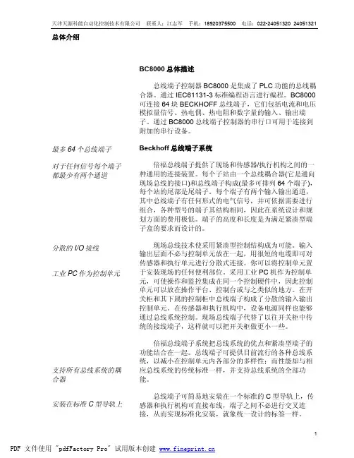
如何正确使⽤Beckhoff产品_2006.01 BECKHOFF⾃动化新技术倍福中国2006年全国销售会议资料如何正确使⽤BECKHOFF 产品(硬件部分)2006年1⽉⽬录第四章正确使⽤Beckhoff 产品(硬件部分) (5)4.1 综述 (5)4.1.1 K-bus 本地总线控制技术 (5)4.1.2 Lightbus 总线技术 (5)4.1.3 通⽤现场总线技术 (5)4.1.4 TwinCAT 实时核技术 (6)4.1.5 EtherCAT 实时以太⽹技术 (6)4.1.5.1 I/O层超⾼速实时以太⽹ (6)4.1.5.2 ⼯作原理 (6)4.1.5.3 端⼦实现以太⽹ (6)4.1.5.4 协议 (7)4.1.5.5 性能 (7)4.1.5.6 EtherCAT 替代PCI (8)4.1.5.7 拓扑结构 (8)4.1.5.8 分布时钟 (8)4.1.5.9 热连接 (8)4.1.5.10 诊断 (9)4.1.5.11 总线端⼦ (9)4.1.5.12 开放性 (9)4.2 产品分类 (9)4.2.1 IPC 类产品 (9)4.2.2 嵌⼊式 PC CX1000 类产品 (10)4.2.3 现场总线类产品 (10)4.2.4 驱动技术类产品 (13)4.2.5 TwinCAT 类产品 (13)4.3 常见问题问答 (14)4.3.1 IPC 类 (14)A001. 使⽤⼯控机应注意的问题 (14)产品中常见技术术语的定义和解释(CP-Link,ADS) (15)A002. BeckhoffA003. 如何解决⼯控机和CX系列的耐温问题? (16)A004. 如何使⼯控机保持安全运⾏ (16)4.3.2 嵌⼊式 PC CX1000 类 (17)B001. 如何恢复 CX1000 /doc/61b15de9daef5ef7ba0d3cb9.html 的出⼚设置 (17)B002. CX1000 系统的供货时间是多长? (18)B003. 什么情况下选⽤ /doc/61b15de9daef5ef7ba0d3cb9.html 和 Windows XP 嵌⼊式操作系统? (18) B004. 如何选择闪存⼤⼩(Windows /doc/61b15de9daef5ef7ba0d3cb9.html /Windows XP 嵌⼊式)? (18) B005. 什么情况下使⽤ 16/32 MB 和 64/128 MB 内存? (19)B006. 什么情况下使⽤ CF 卡和 IBM 微型驱动硬盘? (19)B007. 哪⾥可以找到 CX1000 的技术⽂档资料? (19)B008. 哪些选件(如:现场总线接⼝、附加的串⾏接⼝) 是预安装件,哪些选件可单独订货? (19)B009. CX1000 系统可以连接多少个现场总线接⼝,如何对它们进⾏组态? (20)B010. 能否使⽤ 2 个 CX1000 CPU ⽤于冗余系统? (20)B011. 现有的现场总线接⼝能否既⽤于 Windows /doc/61b15de9daef5ef7ba0d3cb9.html ⼜能⽤于Windows XP 嵌⼊式系统? (20)B012. 什么情况下使⽤ CX1000 带 TwinCAT (PLC 或 NC PTP) 软件的全版本(包括编程/组态⼯具) 或使⽤只安装有运⾏核软件的版本? (20)B013. 需要在我的 CX1000 中注册 TwinCAT (PLC 或 NC PTP 运⾏核) 吗?(20)B014. 当更换⼀套新的 CF 卡时,需要重新注册 TwinCAT (PLC 或 NC PTP 运⾏核) 吗? (20)B015. 在我⽤ CF 卡安装新的映像(更新)后,CX1000 如何检测我在 CX1000 上安装有 TwinCAT PLC (或 NC PTP 运⾏核)?(20)B016. 在 CX1000 上使⽤ TwinCAT NC PTP,可以运⾏多少个轴? (20)B017. CX1000 可以运⾏ TwinCAT NCI 吗? (20)B018. 哪些可视化软件可以⽤于 Windows /doc/61b15de9daef5ef7ba0d3cb9.html 和 Windows XP 嵌⼊式操作系统? (21)B019. 什么情况下使⽤ SCADA 软件和微软开发⼯具? (21)B020. Windows /doc/61b15de9daef5ef7ba0d3cb9.html 和 Windows XP 嵌⼊式映像为何不同,它们之间的区别是什么? (21)B021. 我的应⽤程序可以使⽤多少 RAM ? (21)B022. 我可以更新新的映像版本吗? 如何做? (21)B023. CX1000 的性能如何? (21)B024. 哪些型号的控制⾯板可以⽤于 CX1000? (22)B025. CX1000 可以连接多少个本地端⼦ CX1000? (22)B026. CX1000 中如何与 UPS 系统连线? (22)B027. CX1000 的启动时间是多少? (22)B028. 什么类型的设备可以连接到 USB 接⼝? (22)B029. CX1000 完成了哪些认证并取得了哪些认证证书? (22)B030. CX1000 除可以运⾏于 Windows 操作系统以外,还可以运⾏于哪些操作系统? (22)B031. CX1000 系统能预安装⽤户⾃⼰定制的映像吗? (23)B032. 可以同时使⽤ CX1000-N002 (2xRS232) 和 CX1000-N005 (2xRS422/485) 模块吗? (23)B033. 为什么在样本中出现的导向开关不可⽤? (23)4.3.3 现场总线类 (24)C001. 如何正确设定现场总线的波特率?组⽹时应注意的问题。
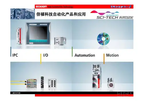
德国倍福(BECKHOFF)产品特点总结德国倍福产品是基于PC控制技术的开放式控制系统,产品范围包括工业PC、现场总线组件、驱动技术和自动化软件。
这些产品既可以作为独立的组件使用,也可将它集成到一个完整的控制系统中,适用于各行业领域。
倍福产品同一标杆的产品也就是竞争对手主要是欧美系一线品牌的自动化产品,例如西门子、AB等,下面我们通过对比对倍福的产品各组成部分进行一个特点分析:1、倍福的现场总线产品技术在国内有过很多成功项目,支持IE61131-3标准PLC语言,支持LIGHTBUS、ProfiBUS、InterBUS、CANopen、DeviceNet、ControlNet、Modbus、SERCOS、RS485、RS232和Ethernet TCP/IP、USB,还有ProfiNET、CC-Link和EtherCAT等现场总线,并可以将不同的现场总线协议整合到一个控制器中,可以根据要求选择不同的总线系统,各种总线系统都采用统一的编程语言。
产品组态灵活,功能强大,精确配置I/O点数,充分考虑用户整体方案综合成本,节省大量布线和空间,为用户提供完善满意的售前售后服务和技术支持!2、各种I/O通用于所有的现场总线系统,只是由不同协议的现场总线耦合器来提供不同的现场总线类型,方便产品的长期应用和选择。
各种I/O端子,包括2点、4点、8点数字量信号(5VDC\24VDC\48VDC\120VDC\230VDC\NAMUR\高速计数器等),模拟量(0-10V,±10V,0-20mA,4-20mA热电偶、热电阻、电阻桥、可接示波器和直接与5/1A电流互感器相连,它可通过现场总线系统进行网络分析和供电管理,采集电流、电压、有效功率、视在功率和功率因数cosφ,每秒64000次采样计算有效值,其测量精度可达到全刻度值的0.1%,广泛用于对电网参数有要求的供配电系统中;也可以控制5.5KW以下电机,通过现场总线对电机进行控制,可以采集电机的电流、电压、有效功率、视在功率和功率因数cosφ以及通断次数,并进行相关的保护。
beckhoff模块说明beckhoff模块说明一、简介beckhoff模块是一种高性能的工业控制模块,广泛应用于各种自动化系统中。
它具有模块化的设计,可以根据实际需求进行灵活组合和配置,满足各种复杂控制任务的要求。
beckhoff模块采用先进的技术和可靠的质量,为工业生产提供了可靠的保障和高效的控制。
二、技术特点1. 高性能:beckhoff模块采用了先进的控制算法和高速通信技术,实现了高精度、高速度的控制。
它可以满足工业生产对精度和速度的要求,提高生产效率和产品质量。
2. 模块化设计:beckhoff模块的设计十分灵活,可以根据实际需求进行灵活组合和配置。
它提供了各种模块,包括数字输入/输出模块、模拟输入/输出模块、通信模块等,用户可以根据实际情况选择合适的模块,组成自己需要的控制系统。
3. 可编程性:beckhoff模块支持多种编程语言,包括C语言、ST语言等,用户可以根据自己的需求选择合适的编程语言进行编程。
它还提供了友好的开发环境和丰富的函数库,方便用户进行编程和调试。
4. 可靠性:beckhoff模块采用了可靠的硬件设计和工艺制造,经过严格的测试和验证,具有良好的稳定性和可靠性。
它能够在恶劣的工作环境中正常工作,并且具有长寿命和低故障率。
三、应用领域beckhoff模块广泛应用于各个领域的自动化系统中,包括工业生产、能源管理、物流运输、医疗设备等。
它可以用于控制各种设备和系统,如机床、输送系统、制造设备等。
同时,beckhoff模块还可以与其他系统进行集成,实现整个生产过程的有效管理和控制。
四、使用案例1. 机床控制:beckhoff模块可以应用于机床控制系统中,实现对机床的高精度、高速度的控制。
它可以控制机床的加工过程、运动轨迹等,并且可以进行数据采集和监控,提高生产效率和产品质量。
2. 物流运输:beckhoff模块可以应用于物流运输系统中,实现对物流运输过程的控制和管理。
它可以对货物进行追踪、定位和分拣,提高物流运输的效率和安全性。
台达CAN模块与BECKHOFF_CAN主站通讯实现方法台达CAN模块与BECKHOFF CAN主站通讯实现方法摘要:本文主要介绍基于标准的CANopen协议,如何实现不同厂牌工业产品之间的高速通讯。
以台达COPM-SL 模块和BECKHOFF EL6751系列CAN主站为例。
关键词:CANopen、主站、高速通讯实现步骤:一、首先打开Delta CANopenBuilder软件。
〉Master parameter。
1,单击Network—2,弹出对话框,如下进行设置,设置完毕后,单击OK。
3,单击Network—〉Online:4,弹出对话框如下,将Simulated online选中,单击OK。
5,单击Network—〉Download:6,等待进度条进行,当进度条结束后,以下对话框会自动消失,如果单击“OK”,则会取消这次下载。
二、通过Twincat PLC Control建立beckhoff PLC程序,将D32——D63设置成T %I* :INT 类型,将D0——D31设置成AT %Q* :INT类型。
A1,打开TwinCAT System Manager软件2,在configuartion状态下进行扫描,扫描出Ethercat slave EK1100,以及EL6751模块。
3,将波特率设置成和从站一样的速率125K。
4,左键单击“Device 2(EL6751)”,单击“Append BOX…” 5,选中“CANopen Node”,单击OK。
6,在新建的Box4中插入“TxPDO1”,“RxPDO1”7,在“TxPDO1”,“RxPDO1”中分别插入4个 UINT类型数据。
,但分别注意,“TxPDO1”与“RxPDO1”起始数据地址都为0 (0x0),SIZE为2是两个数据区。
新建TxPDO,或在TxPDO1下新建数据,必须依次往下设置,不如TxPDO1下面的4个UINT类型数据地址分别为0,2,4,6。
Beckhoff 的自动化技术适用于各种信号和现场总线,可为
所有常用的 I/O 信号、模拟量信号和现场总线系统提供全
系列的现场总线组件。
EtherCAT 是用于实现工业自动化的
以太网解决方案,具有性能优异和操作简单的特点。
本书详述了 Beckhoff 现场总线模块中的测量模块、高精度
模块、XFC 模块和宽温模块。
目录
现场总线端子模块简介
测量模块的的应用
• 只有 12mm 宽的测量仪器
——基于现场总线的测量模块
• 称重模块介绍
• 三相电力模块介绍
• 万用表介绍
• 振动测量模块介绍• 温度测量模块介绍• 高精度模块• XFC 模块• 宽温模块SCOPE VIEW 2 软件介绍
只有 12 mm 宽的测量仪器
——基于现场总线的测量模块
称重模块介绍三相电力测量模块介绍
EL3356 和 EL3356-0010 称重测量端子模块可以直接连接一个电阻桥或者 1 个 6 线制的称重传感器,最终的重量值作为一个过程数据在模块内部计算,不需要在 PLC 上面进行额外的计算。
为了满足各种需求,这系列模块有以下特点:
• 测量误差 <0.01%
• 高分辨率:16 位(EL3356)或者 24 位(EL3356-0010)
• 采样时间:10 ms(EL3356)或者 100 μs(EL3356-0010)
• 电路自整定——消除温漂和时漂
• 分布式时钟模式——可以获取采样数据的具体时间(仅 EL3356-0010)
• 手动输入传感器的铭牌参数(如 KG 和 mV/V)以及通过整定程序来整定传感器的参数(如零平衡点)
• 预制皮重功能,可以在测量值中去掉产品外包装的重量
• 针对高速动态称重的特殊功能
可以使用 EL3356 来实现高精度慢速称重测量任务,而 EL3356-0010 特别适合用于快速、准确监测扭矩或张力的传感器。
此类传感器的应用范围包括:
• 称重任务:慢速料仓测量或快速装袋
• 运动部件的张力测量
• 静载荷下的变形测量和变形报警
• 通过传感器变形进行压力测量EL3403、EL3413 和 EL3773 EtherCAT 电力测量端子模块可以直接通过现场总线对相连工厂或建筑物电网进行能耗分析,也可以对各个用电设备进行具体的能耗数据分析。
EL3403 测量范围为500V AC 3~,1A,通过测量到电压(U)和电流(I)的有效值,EL3403可以计算出有功功率(P),能源消耗(W)以及功率因数(cos j)等。
EL3413 测量范围为 690 V AC 3~,5A,专为直接监测高性能发电机而设计,例如,可用于风力发电行业。
电流输入回路之间互相电气绝缘。
EL3773 测量范围为 500V AC 3~/410V DC,1A AC/1.5A DC。
这是一款极端高速的测量设备,能够以最高达每 100 μs 采样一次的速度测量数值,然后将测量数据传输至控制器。
控制器拥有足够的运算能力来进行有效值或性能的计算,且用户能执行基于所测电压电流的复杂自定
义算法。
万用表模块介绍振动测量模块介绍
端子模块 EL3681/KL3681 能够测量宽输入范围内的电流和电压。
与高级数字万用表一样,其测量范围可自动切换。
目前有两种电流通路可用于电流测量:小电流通路最大为 1 A ,大电流通路最大为 10 A。
交流电、直流电以及测
量的各种量程都可以在模块内部设置。
这款端子模块优点如下:
• 使用现场总线技术的紧凑型万用表
• 测量范围自动切换
• 高精度
• 抗干扰能力良好
测量范围如下:
• DC 300mV/100mA
• DC 3V/1A
• DC 30V/10A
• DC 300V
• AC 300mV/100Ma
• AC 3V/1A
• AC 30V/10A
• AC 300V EtherCAT 端子模块 EL3632 为双通道超采样输入端子模块,每通道每秒的采样率最高可达 50000 次。
至少每20 μs 采样一个模拟量输入值,并存储在缓冲器内,用于 EtherCAT 主站检索。
在二线制模式下,EL3632 最多可连接 2 个 IEPE 传感器。
IEPE 传感器是动态振动传感器,注意:此类动态传感器仅适用于最高与最低极限频率的振动,不适用于无动态运动的静止位置。
除了滤波以外,EL3632 不会对产生的振动振幅值进行预处理,而是由控制器进行处理。
带有数学函数的TwinCAT 功能库可用于评估控制器上的信号。
这将发挥 PC 平台的所有优势,例如,可充分发挥系统性能和灵活性。
另外客户自身的软件也可以用来分析传感器的数据。
加速度传感器应用场合:
• 车速检测、收费站地磅、闯红灯拍照等
• 车床中用于动态切削力的测量
• 用于重要位置出入口、周界安全防护等
•
玻璃破碎报警装置
温度测量模块介绍
高精度模块
XFC 模块1. 热电偶
热电偶传感器使用两线制的方式与 EL331X 模块直接连接。
热电偶是性价比高且易于安装的传感器,可用于测量温度,视热电偶类型的不同,可测量 -200至 +2,300 °C 范围内的温度。
线性化和冷端补偿通过模块内部的特性曲线完成。
断线时,故障 LED 会发出报警指示。
EL3314 的尺寸为 12 mm x 100 mm x 70 mm ,一个 12mm 宽的模块可以测量 4 路热电偶传感器的温度,EL3318 高密度模块可以测量 8 路热电偶传感器温度。
EL3314-0010 则是高精度模块,精度达到 0.01 °C 。
2.铂电阻 EL 320x 系列模拟量输入端子模块可以直接连接电阻式传感器。
端子模块内的微处理器根据设定的特性曲线,将电阻值转换成温度值,并将其线性化。
除此之外,断线情况将报告给控制器,并由 LED 指示灯发出报警。
温度测量可在 -200 至 +850 °C 范围内进行。
温度转换功能可设置为开启或者不开启。
使用三线制或四线制连接可达到最大测量精度(与精度合适的传感器配套使用)。
对于二线制测量,推荐使用 PT1000 或者 Ni1000 传感器。
EL320x-0010 型号的精度较高,分辨率达到 0.01 °C / 数位,需要四线制连接。
(x 代表测量的通道数,分别有 1 路,2 路和 4 路测量)。
XFC 技术(eXtreme Fast Control Technology )基于优化的控制和通讯架构,由先进的工业 PC 、具有可扩展实时特性的超高速 I/O 端子模块、EtherCAT 高速工业以太网系统和 TwinCAT 自动化软件组成。
采用 XFC 技术后,可以实现 100 μs 的 I/O 响应时间。
因此,该技术为以前由于受技术限制而无法满足性能要求的用户提供了一种全方位提升控制性能的新理念。
一般模拟量的分辨率在 12-16 位之间,分
辨率越高,精度越高,Beckhoff 的高精度
模拟量输入模块的分辨率可以达到 24
位,即对于 0-20 ma 的电流信号,电流增
加 0.00000119 ma ,数字量增加 1,另外温
度测量模块的精度可以达到 0.01°。
Top view contact assembly connection
Top view contact assembly connection
2-wire 3-wire 4-wire
宽温模块SCOPE VIEW 2 软件介绍
长期以来,Beckhoff 总线端子模块系统在设备自动化和楼宇自动化领域已得到成功应用,其工作温度范围符合0 …55°C 的标准,可完全满足这些应用领域的要求。
除了满足这些要求之外,Beckhoff 已将一些精心挑选的标准总线端子模块和耦合器的工作温度范围拓展为-20 …+60°C,即宽温模块。
Scope view 2 软件是 Beckhoff 提供的一个用来做信号分析以及数据采集的工具软件,使用 TwinCAT Scope 2 能够充分利用新一代 PC 的图形功能,它具备独立的记录器和观测器。
记录器可以在同一时刻内记录不同通道中的数据并立即保存,需要记录的数据可以来自不同设备。
观测器从记录器采集并显示这些数据。
通过目标浏览器可以选择所要采样的目标设备,并且可以查看到目标设备的变量信息,示波图是在先前的配置基础上实现的,而图表则是 Scope View 2 的实际显示区域。
它们提供 X 轴作为示波图的时间轴。
Y 轴则对应实际采样数据的大小,可以根据采样数据设置上下限。
每个示波图都可以显示多条曲线,而每条曲线则代表一个采样的通道数据。
所有的曲线都可以设置独立的采样周期,并且采样的总时间可以高达几天,即使停止波形显示之后,采集数据的过程依然在后台进行。
Scope view 2 也适合于测量方面的应用,例如:电力测量端子模块以及万用表端子模块都可以使用 Scope view 2做为软件示波器来显示曲线,
采样精度可以达到微秒级。