Alumina–zirconium ceramics synthesis by selective laser sintering.
- 格式:pdf
- 大小:963.49 KB
- 文档页数:5

第30卷第3期硅酸盐学报Vol.30,No.3 2002年6月JOURNAL OF THE CHINESE CERAMIC SOCIETY J u ne,2002一水硬铝石热分解动力学研究李浩群,邵天敏,陈大融(清华大学摩擦学国家重点实验室,北京 100084)摘 要:分别采用等温过程、非等温过程热重-差热联合法测定一水硬铝石(β-AlOOH)的TGA曲线.利用X射线衍射仪对分解前后试样进行了物相分析.经数据处理,得到了不同时段、不同方法下热分解反应的动力学参数E,A和相应的反应机制.结果表2明,一水硬铝石在400℃时开始缓慢反应,反应峰温在510℃附近.其热分解机制比较复杂,并且在转变分数0.85<α<0.90这一区段呈现一个目前无法解释的机制,这可能是两种反应机制同时控制的结果,或者需要建立新的模型.关键词:一水硬铝石;热分解;动力学分析;热重分析;差热分析;X射线衍射中图分类号:TQ170.1 文献标识码:A 文章编号:0454-5648(2002)03-0335-05KINETIC ANALYSIS OF DIASPORE THERMAL DECOMPOSITIONL I Haoqun,S HA O Tianmin,CHEN Darong(The State K ey Laboratory of Tribology,Tsinghua University,Beijing 100084)Abstract:The TG A curves of both isothermal and non-isothermal process of diaspore(β-AlOOH)are obtained by unite of thermo2 gravimetry(TG)and differential thermal analysis(DTA).The phase identification is carried out by X-ray diffraction(XRD)before and after the thermal treatments.The kinetic analysis is established by means of linear regression and twenty common reaction mech2 anism functions are examined.Reaction mechanisms and Arrhenius parameters corresponding to different sections of fraction reacted (α)are presented.It shows that the decomposition of diaspore takes place at temperature of400℃,the peak temperature is about 510℃.The mechanism of this reaction is complicated and within the section of0.85<α<0.90,the reaction mechanism can not be interpreted by any existing kinetic model.It is presumed that two reaction models controlled the reaction simultaneously in this section or a new model should be found.K ey w ords:diaspore;thermal decomposition;kinetic analysis;thermogravimetry;differential thermal analysis;X-ray diffraction α-Al2O3是一种性能优良的陶瓷材料,其工业生产主要是通过煅烧氧化铝水合物来制备.氧化铝水合物Al2O3・x H2O在加热过程中经过各种中间相变最终转化为α-Al2O3,其中,一水软铝石(boehmite,α-AlOOH)、拜尔石[bayerite,β-Al(OH)3]、三水铝石[gibbsite,α-Al(OH)3]的转化过程已经得到了广泛深入的研究[1,2],相比之下,收稿日期:2001-08-17.修改稿收到日期:2001-12-03.基金项目:国家自然科学基金资助项目(59775033).作者简介:李浩群(1973~),男,博士研究生.通信联系人:邵天敏(1963~),男,博士,副教授.人们对一水硬铝石(diaspore,β-AlOOH)的转化过程了解不多.一般认为,由于一水硬铝石和刚玉中的氧原子子晶格都为六方密排列结构,因而一水硬铝石不经任何中间相变直接转变为刚玉.在实际相变过程中,有1/4的氧原子发生迁移、重排形成六方子晶格[3].Carim等人[4]发现在真空条件下,人工合成的一水硬铝石向刚玉的转变过程中形成了过R eceived d ate:2001-08-17.Approved d ate:2001-12-03. Biography:L I Haoqun(1973—),male,postgraduate for doctor degree. Correspondent:SHAO Tianmin(1963—),male,doctor,associate professor.E-m ail:lihq@渡相,并将其命名为α’-Al 2O 3.在中国,绝大部分铝土矿为一水硬铝石型铝土矿[5],其中的一水硬铝石都是和脉石矿共生在一起的,鉴定一水硬铝石及其杂相的结构特征并分析其热分解机理,不仅对控制氧化铝的工业生产过程,而且对直接将一水硬铝石型矿石应用于表面工程领域,如制备氧化铝基复合陶瓷涂层,具有积极的理论指导作用.1 模型判别理论基础50年代以来,人们采用各种的热分析方法来研究固态反应动力学,如热重法(TG )、微分扫描量热法(DSC )、差热法(D TA )、质谱法(MS )、气相色谱法(GC )和X 射线衍射法(XRD )等.经典的固态反应动力学的基本理论是建立在等温过程和均相反应基础上的.对于均相反应,若假设物质的转变分数为α,则从反应开始到结束的整个期间内,α的数值就在0~1的范围之内作单调的变化,反应物的相对浓度应为(1-α),则反应速率方程通常遵循以下速率公式:d αd t=kf (α)(1)引入Arrhenius 方程k =A e -E R T和控温速率β=d T/d t ,方程变为d αd t =A βe -E R T f(α)(2)式中:t 为时间;k 为速率常数;T 为绝对温度;A 为频率因子;E 为反应活化能;R 为气体常数;f (α)为反应机制函数.在此基础上,通过对实验数据的处理,研究人员提出了多种分解机理,推导出一系列动力学方程式.对式(1)、式(2)进行移项积分或微分处理,总可以找到反应模式(机制函数)与时间或温度之间的线性关系,因此,将实验数据以不同反应模式对时间或温度作图,相应的线性关系最好的反应模式即为反应机制.研究中采用计算机处理,将实验数据与20种常用的反应模式(机制函数)进行拟合,由线性回归判断出与之符合最好的反应机制函数[6],在此基础上求出有关的动力学参数,提高了所求动力学参数的精度和机制函数的准确性.2 实 验免检一水硬铝石矿石经粉碎、研磨、酸洗处理、充分洗涤后于120℃烘干.经-200~+500目筛制成试样.其分析组成见表1.热分析实验在TG A92型高温综合热分析仪上进行,仪器热重分析灵敏度为0.001mg.差热分析灵敏度为1mV ,工作温度表1 试样元素组成 T able 1 E lement composition of sample%ElementO Al Si Ti Fe w 49.6942.67 1.13 4.93 1.59x63.9232.550.832.120.59区间为室温至2400℃.以光谱纯Al 2O 3粉作为参比物,气氛为空气,试样1:从室温升至400℃,保温1h ,升温速率β=10℃/min ;试样2:从室温升至500℃,保温0.5h ,升温速率β=10℃/min ;试样3:从室温升至1200℃,升温速率β=5℃/min.所得TG A 曲线分别如图1、图2、图3所示.热重数据漂移0.25~0.50mg ,在数据取值中均加以扣除.试样反应前后利用XRD 技术进行物相鉴定,其分析结果见图4.图1 β-AlOOH 在400℃下等温过程中分解的TG A 曲线Fig.1 TG A plot for β-AlOOH under isothermal processat 400℃图2 β-AlOOH 在500℃等温过程中分解的TG A 曲线Fig.2 TG A plot for β-AlOOH under isothermal processat 500℃・633・ 硅 酸 盐 学 报 2002年 图3 β-AlOOH 在1200℃非等温过程中分解的TG A 曲线Fig.3 TG A plot for β-AlOOH under non-isothermal pro 2cess at 1200℃图4 一水硬铝石试样XRD 分析Fig.4 XRD patterns of the diaspore samples 1———Before heat treatment ;2———Treated at 500℃; 3———Treated at 1200℃3 实验数据处理在反应中的某一时刻,转变分数可由下式求得:α=w 0-w tw 0-w ∞(3)式中:w 0为试样在反应前的初始质量;w t 为反应进行到t 时刻试样的质量;w ∞为反应结束后试样的质量,所得出的转变分数与时间的关系曲线见图5.从α数据中判断出反应起始温度(时间),并计算出质量损失率,与理论值相对照,如表2所示.图5 不同加热条件下转变分数α随时间变化曲线Fig.5 Plots of fraction reacted αagainst time under differ 2ent heating conditions 表2 一水硬铝石在不同条件下的反应起始温度和质量损失T able 2 DTA temperatures and m ass loss of diaspore samplesunder different conditionsConditions ofheat treatment DTA temperature /℃Start temperature Peak temperatureMass loss/%Experimental value Theoretic valueSample 1Mass loss is tiny and the re 2action proceed very slowlySample 242250411.5Sample 3First stage Second stage419915512117712.51.515.0对于等温过程实验数据,由公式(1)移项、积分可得F (α)=kt +c (4)式中:c 为积分常数.将实验数据分别代入各F (α)方程,以计算的F (α)数据对相应的t 数据作图,得出等温过程一水硬铝石的各种反应动力学曲线,如图6所示.对图6进行线性回归,将转变分数α图6 β-AlOOH 在等温过程中(500℃)反应的动力学曲线Fig.6 Reaction kinetic curves of β-AlOOH by isothermalprocess at 500℃・733・ 第30卷第3期 李浩群等:一水硬铝石热分解动力学研究 表3 一水硬铝石等温过程分解(500℃)热分析动力学线性回归结果T able 3 Linear regression results of therm al kinetic analysisby isotherm al process(500℃)αCode name of mechanismF (α)kCorrelation coefficient r[0.0,0.05]D 5[(1+α)1/3-1]20.013310.9968A 4[-ln (1-α)]1/40.001350.9943P 4α1/40.001330.9940[0.05,0.50]R 21-(1-α)1/20.000880.9992A 1.5[-ln (1-α)]1/1.50.002090.9991P 1α0.001490.9991[0.50,0.85]A 1-ln (1-α)0.002430.9998D 4(1-2α/3)-(1-α)2/30.000230.9996D 2α+(1-α)ln (1-α)0.000850.9992[0.85,1.0]A 3[-ln (1-α)]1/30.000480.9998A 2[-ln (1-α)]1/20.000800.9996D 4(1-2α/3)-(1-α)2/30.000180.9996分为不同的区段,分别找出相关性最好的3个动力学方程,如表3所示.对于非等温过程实验数据,由公式(2)移项、两边取对数可得ln{[f (α)]-1d α/d T }=ln (A /β)-ER(1/T )(5)将实验数据分别代入各f (α)方程,以计算的ln{[f (α)]-1d α/d T }数据对相应的1/T 数据作图,得出非等温过程一水硬铝石的各种反应动力学曲线,如图7所示.对图7进行线性回归,将转变分数分为不同的区段,找出相关性最好的3个动力学方程,如表4所示.对其中相关系数为正的区段,结合各种f (α)函数,假设反应模型如下:f (α)=αm(1-α)n [-ln (1-α)]p (6)将公式(4)代入(3)中,进行线性回归计算,搜寻负相关性最好的m ,n 和p 值,以此作为该区段的机制函数.搜索结果为:m =10.90,n =13.00,p =3.81,r =-0.9828.但该函数暂无明确的物理意义,有待于进一步研究.表4 一水硬铝石非等温过程分解(1200℃)热分析动力学线性回归结果T able 4 Linear regression results of therm al kinetic analysis by non-isotherm al process at 1200℃αCode name of mechanism f (α)E /(kJ ・mol -1)ACorrelation coefficient r [0.0,0.05]D 5 1.5(1+α)2/3[(1+α)1/3-1]-1626.900.490e +38-0.9971R 22(1-α)1/2286.920.837e +16-0.9907A 11-α287.830.196e +17-0.9905[0.05,0.50]L 6 1.5(1-α)4/3[(1-α)-1/3-1]-1746.27—-0.9943A 11-α305.400.728e +18-0.9786R 22(1-α)1/2257.080.197e +15-0.9611[0.50,0.85]L 6 1.5(1-α)4/3[(1-α)-1/3-1]-1469.500.948e +29-0.9911D 3 1.5(1-α)2/3[(1-α)1/3]-1208.170.230e +11-0.9362A 11-α115.340.137e +06-0.8787[0.85,0.90]All of the correlation coefficients are plus ,so none of the reaction models is suitable.[0.90,1.0]L 6 1.5(1-α)4/3[(1-α)-1/3-1]-1172.430.431e +08-0.9756A 11-α79.2230.346e +02-0.9741C 1.52(1-α)2/3139.280.310e +06-0.9741・833・ 硅 酸 盐 学 报 2002年 图7 β-AlOOH在1200℃非等温过程中反应的动力学曲线Fig.7 Reaction kinetic curves ofβ-AlOOH by non-isothermal process at1200℃4 结果与讨论从表2中可以看出,试样的分解反应起始温度在420℃左右,峰顶温度在510℃左右,在热重曲线上相应地出现较大的质量损失台阶,从质量损失分数可以计算出试样中一水硬铝石的含量约为83%.反应温度范围低于文献[7]中的一水硬(软)铝石的脱水吸热峰温(530~572℃),这可能是由于矿石中所含赤铁矿在过渡相晶格中提供异类晶核点[8]所致,也可能起因于矿物本身的特殊性质,如分散程度及结构完整程度.单纯依据峰温值,很难把一水铝石的两种晶型区分开来,尤其是软水型峰温明显受粒子大小和结晶好坏的影响,需要辅以其它分析手段进行鉴别,从图4曲线1的XRD分析结果中可以看出,试样的主相为一水硬铝石,杂相主要为金红石,锐钛矿等杂质,未标识峰可能对应于表1中元素Si,Fe的矿物杂质.500℃反应后试样的主相变为α-Al2O3,但杂质相没有发生变化(图4曲线2).相比之下,1200℃反应后α-Al2O3的峰比较锐,并且金红石、锐钛矿、Si和Fe等杂质已经发生了变化(图4曲线3).表3、表4分别为500℃等温过程和1200℃非等温过程试样热分析的动力学线性回归结果.由于机理模型的数学表达式之间存在的差异不是很大,因此在区分两个甚至更多个曲线拟合情况时,要在其中进行取舍有一定困难.表中所列为线性相关最好的前3个机制函数.综合两表,并结合实际反应过程,可以认为,在等温过程下,一水硬铝石分解反应初期由扩散过程控制,反应中期由相界面反应或形核长大控制,反应后期由形核长大控制;在非等温过程下,反应初期也由扩散过程控制,其它阶段由扩散过程或形核长大控制,而区段0.85<α< 0.90为过渡控制区.图1、图2、图3分别为试样在400℃等温过程,500℃等温过程,1200℃非等温过程中的TG A曲线.其中,图2、图3是非常典型的TG A曲线,差热峰和质量损失都非常明显,表明分解反应已经发生.在500℃等温过程中,分解反应后期出现了一个吸热峰,并且TG曲线没有相应的质量损失台阶,而在非等温过程中的这一区段,该吸热峰消失,且对应的线性相关系数为正(见表4),而公式(5)的线性相关为负相关,也就是说,反应机理没有合适的机制函数来解释.这可能是由于在这一区间段,反应由一种不均一的机理控制(两种机理共同控制).另外,从图3中可以看出,在930~1120℃之间,出现了一系列峰,对应TG曲线上出现质量损失台阶,质量损失约为1.5%左右.从上面的XRD分析可知,在这一区段,杂质相发生了相变或反应.其中980℃左右的峰可能对应于高岭石,高岭石在此温度下热分解形成莫来石或尖晶石,在更高温度下形成莫来石[9].从图1可以看出,试样虽然基本没有发生变化,但在开始时有少量的质量损失,与图2、图3中的反应起始温度接近.这说明反应此时可能已经发生,但由于反应初期由扩散过程控制,当保持温度不变,则扩散过程非常缓慢,反应速率很小.图6、图7分别为500℃等温过程和1200℃非等温过程下试样的各种反应动力学曲线.在图6中,除自催化过程和化学反应过程外,其它控制过程曲线比较接近,并且线性关系较好.在图7中,在不同的区段,各控制过程斜率(活化能)变化较大,线性关系相差较大,并且存在一个阶段,所有的曲线斜率为正,这与表4的结果相一致.5 结 论(1)采用计算机处理,将实验数据与各种选定的反应模式(机制函数)进行拟合,由线性回归判断出与之符合最好的反应机制函数,在此基础上求出有关的动力学参数,提高了所求动力学参数的精度和机制函数的准确性.(2)采用的一水硬铝石型铝土矿,品位高,一水硬铝石含量约为83.3%,分解反应起始温度为(continued on p.346)・933・ 第30卷第3期 李浩群等:一水硬铝石热分解动力学研究 3 结 论(1)B 2O 3-TiO 2-Mg -C 体系可利用SHS 技术合成出TiB 2-TiC 陶瓷复合粉.(2)热力学分析其化学反应机理为:Mg 先还原B 2O 3和TiO 2,新生的Ti 与B 和C 反应生成TiB 2和TiC ;TiO 2的还原经历了TiO 2Ti 3O 5TiOTi 2O Ti 的逐步还原过程.(3)B 2O 3-TiO 2-Mg -C 体系SHS 反应过程的产物结构形成机理分析表明:当燃烧区的能量传到预反应区时,B 2O 3首先熔化并均匀地包裹在Mg ,TiO 2和C 周围,Mg 熔化后加速了与B 2O 3和TiO 2反应,放出大量的热,随着预反应区温度的升高,B 2O 3与Mg 作用还原出B ,TiO 2与Mg 作用还原出Ti ,Ti 与B 或C 反应而形成TiB 2或TiC 晶核,最后TiB 2与TiC 及MgO 在持续高温下长大.参考文献:[1] LASZ LO J K ,THOMAS K ,ANDRUS N.Microstructural prop 2erties of combustion-synthesized and dynamically consolidated tita 2nium diboride and titanium carbide [J ].J Am Ceram Soc ,1990,73(5):1274—1282.[2] DAVIES T J ,O GWU A A.TiC plus TiB 2composite shows wearpromise [J ].Metal Powder Report ,1997,52(6):31—34.[3] YURIY A L ,EV GEN G A ,SHEV EIKO A.Electrochemicalcorrosion behavior of SHS -synthesized magnetron composite TiC -based targets and sputtered thin films [J ].Surf Coat Technol ,1997,90(1-2):42—52.[4] ZHAO H C ,YI B.Formation of TiB 2-TiC composites by reac 2tive sintering [J ].Ceram Int ,1999,25(4):353—358.[5] SU GIYAMA ,SHIGEA KI K ,MITSU HIKO A ,et al .Synthe 2sis of a TiB 2-TiC composite by reactive spark plasma sintering of B 4C and Ti [J ].J Jpn Soc Powder Powder Metall ,1998,45(11):1065-1070.[6] 梁英教,车荫昌主编(L IAN G Y ingjiao ,et al ).无机物热力学数据手册(Handbook of Thermodynamic Data of Inorganic Mat 2ters )[M ].沈阳:东北大学出版社(Shengyang :North East Uni 2versity Press ),1995.7—68.※※※※※※※※※※※※※※※(continued from p.339)420℃左右,峰顶温度为510℃左右.在等温过程和非等温过程中的反应机制不完全相同,在转变分数0.85<α<0.90区段,反应由两个机制共同控制.(3)对我国铝土矿主要矿型一水硬铝石,鉴定矿石中氧化铝及其杂相的结构特征并分析其热行为,对此矿石的开发应用,具有积极的理论指导作用.参考文献:[1] NOVA K C ,PO KOL G ,IZV EKOV V.Studies on the reactionsof aluminium oxides and hydroxides [J ].J Therm Anal ,1990,36:1895—1909.[2] PYZALSKI M ,WOJ CIK M.The dehydroxylation of aluminiumhydroxides and the kinetics of α-Al 2O 3formation [J ].J Therm Anal ,1990,36:2147—2151.[3] COLL IS D N.Thermal chemically formed ceramic coatings :theprocess and applications [J ].Trans Inst Met Finish ,1987,65:83—88.[4] CARIM A H ,ROHRER G S ,DANDO N R.Conversion of dias 2pore to corundum :A new α-alumina transformation sequence [J ].J Am Ceram Soc ,1997,80(10):2677—2680.[5] 毕诗文,杨毅宏,李殿锋,等(BI Shiwen ,et al ).铝土矿的拜耳法溶出(Bayer Process Stripping of Alumyte )[M ].北京:冶金工业出版社(Beijing :The Metallurgical Industry Press ),1997.17页.[6] 罗世永,张家芸,周 坪,等(LUO Shiyong ,et al ).固相反应合成Sr TiO 3的反应动力学[J ].硅酸盐学报(J Chin CeramSoc ),2000,28(5):458—461.[7] 黄佰龄(HUAN G Bailing ).矿物差热分析鉴定手册(MineralIdentification Manual via Differential Thermal Analysis )[M ].北京,科学出版社(Beijing :Science Press ),1987.50页.[8] MCARDL E J L ,MESSIN G G L.Solid-phase epitaxy ofboehmite -derived α-alumina on hematite seed crystals [J ].J Am Ceram Soc ,1989,72(5):864—867.[9] 刘长龄,刘钦甫,陈济舟,等(L IU Changling ,et al ).变高岭石的结构研究[J ].硅酸盐学报(J Chin Ceram Soc ),2001,29(1):63—67.・643・ 硅 酸 盐 学 报 2002年 。

MEMS和半导体工艺材料配比苏州能斯达电子科技有限公司的工程师整理了MEMS和半导体工艺中接近50种材料的湿法腐蚀的刻蚀液及配比,趁着新年,给大家送一份豪华大礼包。
1.铝-Aluminum2.砷化铝镓-Aluminum Gallium Arsenide1.1:1:30 –H2SO4:H2O2–60 Å/sec2.8:3:400 –NH3:H2O2:H2O–25 Å/sec3.1:1:10 –HF:H2O2:H2o–80 Å/sec3.三氧化二铝/铝/蓝宝石-Aluminum Trioxide / Alumina /Sapphire1.1:1:3 –NH4OH:H2O2:H2O–80 ℃2.10% Br2:MeOH3.7ml:4g –H3PO:Cr2O34.锑-Antimony1.1:1:1 –HCl:HNO3:H2O2.90:10:1 –H2O:HNO3:HF3.3:3:1:1 –H3PO4:HNO3:CH3COOH:H2O <<3min/1000A 50℃5.铋-Bismuth1.10:1 –H2O:HCl6.黄铜-Brass1.FeCl32.20% NHSO57.青铜-Bronze1.1% CrO38.碳-Carbon1.H3PO4:CrO3:NaCN2.50% KOH (or NaOH)–boiling3.HNO3 concentrated4.H2SO4 concentrated5.3:1 –H2SO4:H2O29.铬 -Chromium1.2:3:12 KMnO4:NaOH:H2O2.3:1 –H2O:H2O23.HCl concentrated and dilute4.3:1 –HCl:H2O25.2:1 –FeCl:HCl6.Cyantek CR-7s (Perchloric based) 7 min/micron (24A/s new)7.1:1 –HCl:glycerine 12min/micron after depassivation8.1:3 –[50gNaOH+100mlH2O]:[30gK3Fe(CN)6+100mlH2O] 1hr/micron10.钴-Cobalt1.1:1 H2O:HNO32.3:1 HCl:H2O211.铜-Copper1.30% FeCl3 saturated solution2.20% KCN3.1:5 –H2O:HNO34.HNO3 concentrated and dilute5.1:1 –NH4OH:H2O26.1:20 –HNO3:H2O27.4:1 –NH3:H2O28.1:1:1 –H3PO4:HNO3:HAc9.5ml:5ml:4g:1:90ml –HNO3:H2SO4:CrO3:NH4Cl:H2O10.4:1:5 –HCL:FeCl3:H2O12.环氧树脂-Epoxies1.General Polymer Etch2.5:1 –NH4OH:H2O2–120 ℃3.Gold Epoxy4.3:1:10 HNO3:HCl:H2O5.Silver Epoxy6.1:3 –HF:HNO37.Aluminum Epoxy8.H2SO4 –hot9.SU8 cured10.3:1 –H2SO4:H2O2–hot13.砷化镓-Gallium Arsenide1. 1.5%-7.5% –Br2 in CH3OH2.1:1 –NH4OH:H2O23.20:7:973 –NH4OH:H2O2:H2O4.40:1:40 –H3PO4:H2O2:H2O5.3:1:50 –H3PO4:H2O2:H2O6.33-66% –HNO3–red fuming etches more rapidly than whitefuming7.1:1 –HF:HNO38.1:1 –H2SO4:H2O29.1:1:30 –H2SO4:H2O2–60 Ås/sec10.8:3:400 –NH3:H2O2:H2O–30 Ås/sec, isotropic11.1:1:10 –HF:H2O2:H2o–80 Ås/sec14.锗-Germanium1.HF:HNO3:H2O2.1:1:1 –HF:HNO3:HAc3.7:1:x HF:HNO3:glycerin 35c 75-100 microns/hour, 100℃775microns/hour4.KF–pH > 65.1:25 NH3OH:H2O21000 Å/min15.金-Gold1.Aqua Regia 3:1 –HCl:HNO3 10-15 microns/min RT, 25-50microns/min 35 ℃2.Chrome Regia 3:10-20% HCl:CrO33.H2SeO4–Temp should be hot, etch is slow4.KCN in H20–good for stripping gold from alumina, quartz, sapphiresubstrates, semiconductor wafers and metal parts5.4g:2g:10ml –KI:I2:H2O Hot (70℃) 280 nm/min6.1:2:3 –HF:HAc:HNO37.30:30:50:0.6 –HF:HNO3:HAc:Br28.NaCN:H2O29.7g:25:g:100ml –KI:Br2:H2O10.9g:1g:50ml –KBr:Br2:H2O 800 nm/min11.9g:1g:50ml –NaBr:Br2:H2O 400nm/min12.400g:100g:400ml –I2:KI:H2O 55℃1270Ås/sec13.1:2:10 –I2:KI:H2O14.Au mask etch 4g:1g:40ml –KI:I2:H2O 1min/micron16.铪-Hafnium1.20:1:1 –H2O:HF:H2O217.铟-Indium1.Aqua Regia 3:1 –HCl:HNO3 hot2.HCl boiling, fast3.IPA4.EOH5.MeOH6.Rare Earth Indium Etchants18.砷化铟镓-Indium Gallium Arsenide1.1:1:20 –H2SO4:H2O2:H2O–30 Ås/sec19.镓铟磷-Indium Gallium Phosphide1.conc HCl–fast20.磷化铟-Indium Phosphide1.1:1 –HCl:H3PO4–fast21.磷化铟氧化物腐蚀剂-Indium Phosphide Oxide Etchants1.NH4OH22.ITO-Indium Tin Oxide1.1:1 –HCl:H2O8 Ås/sec2.1:1:10 –HF:H2O2:H2O125 Ås/sec23.铱-Iridium1.Aqua Regia 3:1 –HCl:HNO3 hot24.铁-Iron1.1:1 –H2O:HCL2.1:1 –H2O:HNO33.1:2:10 –I2:KI:H2O25.铅-Lead1.1:1 –HAc:H2O226.镁-Magnesium1.10ml:1g –H2O:NaOH followed by 5ml:1g –H2O:CrO3 27.钼-Molybendum1.1:1 –HCl:H2O228.镍-Nickel1.1:1:1 –HNO3:HAc:Acetone2.1:1 –HF:HNO33.30% FeCl34.3:1:5:1 –HNO3:H2SO4:HAc:H2O 85 C 10 microns/min5.3:7 –HNO3:H2O6.1:1 –HNO3:HAc7.10% g/ml Ce(NH4)2(NO3)6:H208.HF, concentrated –slow etchant9.H3PO4 –slow etchants10.HNO3 –rapid etchant11.HF:HNO3 –etch rate determined by ratio, the greater the amountof HF the slower the reaction12.4:1 –HCl:HNO3 –increase HNO3 concentration increases etchrate13.30% FeCl314.5g:1ml:150ml –2NH4NO3.Ce(NO3)3.4(H2O):HNO3:H2O –decreasing HNO3 amount increases the etch rate15.3:3:1:1 –H3PO4:HNO3:CH3COOH:H2O ~15min/micron @ RT withair exposure every 15 seconds29.铌-Niobium1.1:1 –HF:HNO330.钯-Palladium1.Aqua Regia 3:1 –HCl:HNO3 hot31.光刻胶-Photoresist (AZ type)1.General Polymer2.5:1 –NH4OH:H2O2 –120 ℃3.5:1 –H2SO4:H2O24.H2SO4:(NH4)2S2O85.Acetone32.铂-Platinum1.Aqua Regia 3:1 –HCl:HNO3 Hot2.Molten Sulfur33.聚合物-Polymer1.5:1 –NH4OH:H2O2 –120 ℃2.3:1 –H2SO4:H2O234.聚合物-Polymer1.1:1 –HF:H2O2.1:1 –HF:HNO33.Sodium Carbonate boiling4.HF conc35.铼、铑和钌-Rhenium, Rhodium and Ruthenium1.Aqua Regia 3:1 –HCl:HNO3 –Hot36.硅-Silicon1.64:3:33 –HNO3:NH4F:H2O 100 Ås/s2.61:11:28 –ethylenediamine:C6H4(OH)2:H2O 78 Ås/s3.108ml:350g:1000ml –HF:NH4F:H2O slow 0.5 Ås/min4.1:1:50 –HF:HNO3:H2O slow etch5.KCl dissolved in H2O6.KOH:H2O:Br2/I27.KOH –see section on KOH etching of silicon8.1:1:1.4:0.15%:0.24% –HF:HNO3:HAc:I2:triton9.1:6:3 –HF:HNO3:HAc and 0.19 g NaI per 100 ml solution10.1:4 –Iodine Etch:HAc11.0.010 N NaI12.NaOH13.HF:HNO314.1:1:1 –HF:HNO3:H2O37.二氧化硅/石英/玻璃-Silicon Dioxide / Quartz / Glass1.BOE 1:5:5 HF:NH4HF:H2O 20 Ås/s2.HF:HNO33.3:2:60 HF:HNO3:H20 2.5 Ås/sec at RT4.BHF 1:10, 1:100, 1:20 HF:NH4F(sat)5.Secco etch 2:1 HF:1.5M K2Cr2O76.5:1 NH4.HF:NaF/L (in grams)7.1g:1ml:10ml:10ml NH4F.HF:HF:H2O:glycerin8.HF –hot9.1:1 1:15, 1:100 HF:H2O10.BOE HF:NH4F:H2O11.1:6 BOE:H2O12.5:43, 1:6 HF:NH4F(40%)13.NaCO3 100 ℃8.8 mm/h14.5% NaOH 100 ℃150 mm/h15.5% HCl 95 ℃0.5mm/day16.KOH see KOH etching of silicon dioxide and silicon nitride38.氮化硅-Silicon Nitride1.1:60 or 1:20 HF:H2O 1000-2000 Ås/min2.BHF 1:2:2 HF:NH4F:H2O slow attack –but faster for siliconoxynitride3.1:5 or 1:9 HF:NH4F (40%)0.01-0.02 microns/second4.3:25 HF:NH4F.HF(sat)5.50ml:50g:100ml:50ml HF:NH4F.HF:H2O:glycerin –glycerinprovides more uniform removal6.BOE HF:NH4F:H2O7.18g:5g:100ml NaOH:KHC8H4O4:H2O boiling 160 Ås/min, betterwith silicon oxynitride8.9:g25ml NaOH:H20 –boiling 160Ås/min9.18g:5g:100ml NaOH:(NH4)2S2O8:H2O –boiling 160 Ås/min10.A) 5g:100ml NH4F.HF:H2O B)1g:50ml:50ml I2:H2O:glycerin –mixA andB 1:1 when ready to use. RT 180 A/min39.银-Silver1.1:1 NH4OH:H2O22.3:3:23:1 H3PO4:HNO3:CH3COOH:H2O ~10min/100Ås3.1:1:4 NH4OH:H2O2:CH3OH .36micron/min resist5.1-8:1HNO3:H2O6. 1 M HNO3 + light40.不锈钢-Stainless Steel1.1:1 HF:HNO341.钽-Tantalum1.1:1 HF:HNO342.锡-Tin1.1:1 HF:HCL2.1:1 HF:HNO33.1:1 HF:H2O4.2:7 HClO4:HAc43.钛-Titanium1.50:1:1 H2O:HF:HNO32.20:1:1 H2O:HF:H2O23.RCA-1 ~100 min/micron4.x%Br2:ethyl acetate –HOT5.x%I2:MeOH –HOT6.HF:CuSO47.1:2 NH4OH:H2O28.1:2:7, 1:5:4, 1:4:5(18 microns/min), 1:1:50 HF:HNO3:H2O9.COOHCOOH:H2O –any concentration11.1:9 HF:H2O –12 Ås/min12.HF:HCL:H2O13.HCL –conc14.%KOH –conc15.%NaOH- conc16.20% H2SO4 1 micron/minl3COOC2H518.25%HCOOH19.20%H3PO420.HF44.钨-Tungsten1.1:1 HF:HNO32.1:1 HF:HNO3 –thin films3.3:7 HF:HNO34.4:1 HF:HNO3 –rapid attack5.1:2 NH4OH:H2O2 –thin films good for etching tungsten fromstainless steel, glass, copper and ceramics. Will etch titanium aswell.6.305g:44.5g:1000ml K3Fe(CN)6:NaOH:H2O –rapid etch7.HCl –slow etch (dilute or concentrated)8.HNO3 –very slow etch (dilute or concentrated)9.H2SO4 –slow etch (dilute or concentrated)10.HF –slow etch (dilute or concentrated)11.H2O212.1:1, 30%:70%, or 4:1 HF:HNO313.1:2 NH4OH:H2O214.4:4:3 HF HNO3:HAc15.CBrF3 RIE etch16.305g:44.5g:1000ml K3Fe(CN)6:NaOH:H2O –very rapid etch17.HCl solutions –slow attack18.HNO3 –slight attack19.Aqua Regia 3:1 HCL:HNO3 –slow attack when hot or warm20.H2SO4 dilute and concentrated –slow etch21.HF dilute and concentrated –slow etch22.Alkali with oxidizers (KNO3 and PbO2) –rapid etch23.H2O245.钒-Vanadium1.1:1 H2O:HNO32.1:1 HF:HNO346.锌-Zinc1.1:1 HCl:H2O2.1:1 HNO3:H2O47.锆-Zirconium1.50:1:1 H2O:HF:HNO32.20:1:1 H2O:HF:H2O2更多精彩内容欢迎关注MEMSVIEW微视界。

Journal of Materials Processing Technology168(2005)262–269Process optimisation for a squeeze cast magnesium alloy metalmatrix compositeM.S.Yong a,∗,A.J.Clegg ba Singapore Institute of Manufacturing Technology,71Nanyang Drive,Singapore638075,Singaporeb Wolfson School of Mechanical and Manufacturing Engineering,Loughborough University,Loughborough,Leicestershire LE113TU,UKReceived5January2004;received in revised form5January2004;accepted27January2005AbstractThe paper reports the influence of process variables on a zirconium-free(RZ5DF)magnesium alloy metal matrix composite(MMC) containing14vol.%Saffilfibres.The squeeze casting process was used to produce the composites and the process variables evaluated were applied pressure,from0.1MPa to120MPa,and preform temperature from250◦C to750◦C.The principalfindings from this research were that a minimum applied pressure of60MPa is necessary to eliminate porosity and that applied pressures greater than100MPa causefibre clustering and breakage.The optimum applied pressure was established to be80MPa.It was also established that to ensure successful preform infiltration a preform temperature of600◦C or above was necessary.For the optimum combination of a preform preheat temperature of600◦C and an applied pressure of80MPa,an UTS of259MPa was obtained for the composite.This represented an increase of30%compared to the UTS for the squeeze cast base alloy.©2005Elsevier B.V.All rights reserved.Keywords:Magnesium alloys;Squeeze casting;Metal matrix composites;Mechanical properties1.IntroductionMetal matrix composite(MMC)components can be man-ufactured by several methods.The metal casting route is espe-cially attractive in terms of its ability to produce complex near net shapes.However,castings produced by conventional cast-ing processes may contain gas and/or shrinkage porosity.The tendency for porosity formation will be exacerbated whenfi-bres are introduced because they tend to restrict theflow of molten metal and cause even greater gas entrapment within the casting.It is pointless to usefibres to reinforce a casting if defects are present,since the addition offibres will not com-pensate for poor metallurgical integrity.In order to fulfil the potential offibre reinforcement and produce pore free cast-ings the squeeze casting process can be selected.The unique feature of this process is that metal is pressurised throughout solidification.This prevents the formation of gas and shrink-age porosity and produces a metallurgically sound casting.∗Corresponding author.E-mail address:msyong@.sg(M.S.Yong).Selection of this process is also based on its suitability for mass production,ease of fabrication and its consistency in producing high quality composite parts.With the development of MMCs,magnesium alloys can better meet the various demands of diverse applications.The addition of reinforcement to magnesium alloy produces su-perior mechanical properties[1–3]and good thermal stability [4,5].Of the various composite types,the discontinuous and randomly orientedfibre-reinforced composites provide the best“value to strength ratio”.Despite the potential advantage of using magnesium MMC for lightweight and high strength applications,little is known about the influence of squeeze infiltration parame-ters.Key parameters,such as applied pressure and preform temperature must be optimised,especially for the squeeze infiltration of a magnesium–zinc MMC.These process pa-rameters were researched and the results are presented in this paper.However,it wasfirst necessary to select appropriate fibres and binders since their selection is fundamental to the success of the MMC.The main criterion determining the se-lection offibre type is compatibility with the matrix.Two0924-0136/$–see front matter©2005Elsevier B.V.All rights reserved. doi:10.1016/j.jmatprotec.2005.01.012M.S.Yong,A.J.Clegg/Journal of Materials Processing Technology168(2005)262–269263fibre types that are known to be compatible with magnesium are Saffil and carbon[6].Silica and alumina-based binders are widely used in preform production,mainly due to their high temperature properties[7].However,there are concerns about chemical reactions between magnesium alloys and sil-ica[8].To ensure full infiltration of liquid metal into thefibre pre-form,researchers[9–11]have emphasised the importance of preheating the preforms.However,there has been lit-tle research to determine optimum preform temperature for magnesium alloys and that reported has focused on AZ91 (magnesium–aluminium)alloy.The wetting capability of these alloys is different,for instance the wetting and the in-terfacial reaction between Al2O3reinforcement and cerium, lanthanum(both rare earth elements)or magnesium is far better in comparison to aluminium.Most work on applied pressure has focused on aluminium alloys and their composites.However,Ha[12]and Chadwick [13]investigated the influence of applied pressure on the short freezing range Mg–Al family of alloys.The effect on solid-ification will inevitably be different for long freezing range alloys,such as the Mg–Zn family alloys that are the focus of this research.The difference in solidification morphology will be significant when infiltrating the melt into a porousfi-bre preform.Long freezing range alloys retain a liquid phase over a longer period during infiltration and this may promote better infiltration,reduce voids and consequently improve the soundness of the composite.2.Experimental methodologyA zirconium-free magnesium–4.2%zinc–1%-rare earths alloy,designated RZ5DF,was used for this research.Several fibre preform materials,proportions and binder systems,were evaluated to determine their compatibility with the magne-sium alloys and the mechanical properties that they delivered to the composite[14].This preliminary research established that a compopsite based on a silica-bonded,14vol.%Saffil fibre preform delivered the best characteristics in terms of ease of production and maximum‘value to strength ratio’.The effect of applied pressure,between0.1MPa and 120MPa,on the RZ5DF-14vol.%Saffilfibre composite was first evaluated.The maximum permissible applied pressure was limited by both the capability of the squeeze casting press and die design.The metal pouring temperature was main-tained at750◦C,the die temperature at250◦C,the duration of applied pressure at25s,and delay before application of pressure at4s.These conditions replicated those employed for the base alloy that was reported previously[15].Following this,the influence of preform temperature was evaluated for a restricted range of applied pressures.Four preform temperatures were selected:250◦C(similar to the die temperature),400◦C(intermediate temperature),600◦C (at which temperature the RZ5DF alloy is a mixture of liquid and solid),and750◦C(at which temperature the RZ5DF alloy is in the fully molten state).These experiments were conducted at three applied pressures:60MPa,80MPa and 100MPa.The mechanical properties were evaluated using tensile and hardness tests.These tests were complemented by optical microscopy and,for the tensile fracture surfaces,SEM.2.1.Test castingThe test casting was a rectangular plate of126mm in length,75mm in width and16mm in depth.2.2.Melt processingThe alloy was melted in an electric resistance furnace us-ing a steel crucible,thefluxless method and an argon gas cover.The die was coated with boron nitride suspended in water to protect it from excessive wear.2.3.Tensile testingTensile tests were conducted on a50kN Mayes testing ma-chine using position control.Modified test specimens were machined according to BS18(1987)and magnesium Elek-tron Ltd RB4specifications[16].2.4.Hardness testingHardness was measured to determine and study the influ-ence of reinforcement on the magnesium and the isotropy of fibre distribution.The locations of hardness measurements are shown in Fig.1.Hardness measurements were conducted using the Rockwell B scale for both the alloys and com-posites.The preference for the Rockwell rather than Vick-ers hardness measurement was due to the larger indentation needed to ensure a more consistent measurement on the com-posite.The area of the Vickers hardness indentation is so small that,in some cases,the measurement could be taken from the hardfibre causing large variations in hardness val-ues.Fig.1.Locations of hardness measurements(each dot represents the position of a hardness measurement)taken in both‘Longitudinal’and‘Transverse’directions.264M.S.Yong,A.J.Clegg /Journal of Materials Processing Technology 168(2005)262–2692.5.MetallographyAn optical microscope and stereoscan 360electrom mi-croscope (SEM)were used to examine the microstructure of the MMC specimens.Metallographic samples were prepared using standard techniques and were etched using an acetic pi-cral solution.The electron microscope was equipped with a back-scatter detector and was used to characterise fracture surfaces from the tensile test specimens.2.6.Cell sizeThe cell size was established using the intersection method.Five areas were selected at random and 21mea-surements of cell size were taken for each area.The average value for the 105readings was determined.3.Results and observationsThe results are reported in the sequence in which the ex-periments were conducted.In the first series of experiments,the effect of applied pressure was evaluated.In the second se-ries,the combined influences of applied pressure and preform preheat temperature were evaluated.3.1.Series 1experiments:the influence of applied pressure3.1.1.Tensile propertiesThe effect of applied pressure on UTS and ductility of squeeze cast,RZ5DF-14vol.%,Saffil fibre composites is shown in Fig.2.It can be seen that the highest UTS value was obtained with an applied pressure of 80MPa.It would appear from the figure that a pressure in excess of 40MPa is essential to develop a significant improvement in UTS but that levels above 80MPa have a detrimental effect.3.1.2.HardnessThe hardness values along the longitudinal and transverse directions of the composite castings produced atdifferentFig.2.The effects of squeeze infiltration applied pressure on the tensile properties of the RZ5DF matrix with 14vol.%fraction Saffilfibres.Fig.3.The average material hardness along the longitudinal and transverse direction of the squeeze infiltrated RZ5DF alloy with 14vol.%fraction Saffil fibres,cast with constant pouring temperature of 750◦C and die temperature of 250◦C.applied pressures are shown graphically in Fig.3.Whilst the dominating influence on hardness is provided by the presence of the Saffil fibres,the results show that the hardness at the two lowest levels of applied pressure (0.1MPa and 20MPa)is distinctly lower than that associated with applied pressure levels of 40MPa and above.3.1.3.MetallographyMetallography was conducted to examine the influence of applied pressure on the cast structure.Selected opti-cal microstructures are presented in Fig.4.The metal-lographic examination identified the presence of microp-orosity in those samples produced with applied pressures below 60MPa.The microporosity,as expected,occurred mainly at cell boundaries and was most easily confirmed by adjusting the depth of field.It also identified the ten-dency for fibre clustering and fracture at applied pressures greater than 80MPa.The presence of fractured fibres is demonstrated more clearly in the SEM micrographs shown in Fig.5.These micrographs show fractured fibres in the plane transverse to that of load application during the tensile test.3.2.Series 2experiments:the influence of preform temperatureThe preliminary experiments showed that the optimum applied pressure was 80MPa.However,to ensure robustness in the experimentation,the effects of preform preheat temper-ature were evaluated for the optimum applied pressure and pressures of 60MPa and 100MPa.3.2.1.Tensile testsThe effects of preform temperature and applied pressure on UTS are summarised in Fig.6.The results show that a preform preheat temperature of 750◦C produced the most consistent UTS values across the range of applied pressuresM.S.Yong,A.J.Clegg/Journal of Materials Processing Technology168(2005)262–269265Fig.4.Optical microstructure of squeeze infiltrated RZ5DF-14vol.%fraction Saffilfibres produced under(i)atmospheric pressure,0.1MPa,applied pressure of(ii)20MPa,(iii)40MPa,(iv)60MPa,(v)80MPa,(vi)100MPa and(vii)120MPa.and that the maximum UTS of259MPa was obtained with a preform temperature of600◦C and an applied pressure of 80MPa.These results confirm the status of80MPa as the optimum value of applied pressure.3.2.2.HardnessThe results of the hardness tests are shown in Fig.7.The greatest variation in hardness was demonstrated by the test casting produced with the lowest value of appliedpressure Fig.5.SEM micrograph of the fracture face of a squeeze infiltrated RZ5DF-14vol.%fraction Saffilfibres produced under applied pressure of(i)100MPa and (ii)120MPa.266M.S.Yong,A.J.Clegg/Journal of Materials Processing Technology168(2005)262–269Fig.6.The plot of UTS for RZ5DF-14vol.%Saffil MMC produced from various combinations of applied pressure and preform temperature. (60MPa)and preform temperature of400◦C.The range of variation was±8HRB compared to±6HRB observed for the other combinations of preform temperature and applied pressure.3.2.3.MetallographyMetallographic examination of the composite structures showed that more densely packedfibres occurred at the pre-form surface at the lowest preform temperature.This effect is illustrated in Fig.8.The sequence of microstructures show that preform deformation andfibre clustering were less evi-dent at higher preform temperatures.The SEM micrographs of tensile fracture surfaces,Fig.9,confirm the clustering of fibres and provide evidence offibre tofibre contact,for the preheat temperature of400◦C.This effect was not evident for the preheat temperature of600◦C.4.DiscussionTo achieve the successful infiltration of afibre preform the liquid metal must penetrate the preform completely.Potential barriers to this are presented by:the density of the preform, which can be represented by the preform permeability[14]; Fig.7.The average material hardness along the longitudinal and transverse direction of the squeeze infiltrated RZ5DF alloy with14vol.%fraction Saffilfibres produced under different combinations of preform temperatures and appliedpressures.Fig.8.A micrograph taken at the preform infiltration region of a squeeze infiltrated specimen produced with a preform temperature of(i)750◦C,(ii)600◦C, (iii)400◦C and(iv)250◦C.M.S.Yong,A.J.Clegg/Journal of Materials Processing Technology168(2005)262–269267an insufficient pressure head,necessary to displace the air and overcome resistances to metalflow;and/or a low pre-form temperature that promotes premature solidification of the solid before complete infiltration.Increasing either the applied pressure or the preform pre-heat temperature,independently or in combination,may im-prove infiltration.However,there may be adverse conse-quences.Too high a level of applied pressure may physi-cally damage the preform through compression.This leads to compacted preforms that resist infiltration together withfi-bre clustering andfibre breakage that reduce thefibres’effec-tiveness for strengthening the matrix.Although researchers [11,17,18]have resorted to high preform temperatures to achieve infiltration,this too can have adverse effects.For example,an increased heat content in the system may retard solidification.This in turn extends the time during which there is the opportunity for adverse interfacial reactions to occur between the alloy andfibres.Furthermore,an extended pe-riod of solidification can promote the formation of larger cell sizes that in turn impair the mechanical properties.The influence of applied pressure is quite clearly demon-strated in Fig.2.Thefigure can be divided into three distinct regions:<60MPa,61–90MPa,>91MPa.Thefirst of these regions is associated with the presence of porosity and voids in the castings and this porosity is associated with low UTS values.As the applied pressure is increased the porosity is eliminated and the composite develops its optimum UTS of 259MPa at an applied pressure of80MPa.Thereafter,an increase in applied pressure producesfibre clustering and breakage leading to more initiation points for fracture and so the UTS declines.The tensile evidence is supported by evi-dence from hardness tests and metallography.The presence of porosity,revealed in Fig.4,adversely affects the hardness of the castings.Quite simply,low levels of applied pressure are not sufficient to either suppress porosity formation or com-pletely infiltrate thefibre preform.It is interesting to note that the optimum applied pressure level of80MPa for the compos-ite is20MPa higher than that necessary to develop the highest level of strength in thefibre-free base alloy[15].Metallo-graphic examination revealed that preform deformation and fibre clustering was less evident andfibres were less densely packed at the surfaces of the preforms preheated to600◦C or 750◦C(see Fig.8)when compared with400◦C and250◦C.It was found that the highest preform temperature(750◦C) produced the most consistent UTS values over the range of applied pressures considered.This preform temperature is above the liquidus temperature of the alloy.It would,there-fore,be expected that infiltration of the preform would not be impeded by the early onset of solidification of the alloy on thefibre preforms.The preform temperature of600◦C pro-duced a higher variation in UTS than was observed for the 750◦C preform preheat temperature.However,the highest value of UTS of all the experiments was produced with this preheat temperature in combination with an applied pressure of80MPa.A preform temperature of750◦C supported a wider range of applied pressure because,even at the lowest level of 60MPa,there was a minimal resistance to infiltration.It was also noted that there was less variation infibre distri-bution.An even distribution offibres was also evident in the specimens produced at a preheat temperature of600◦C, see Fig.9.This temperature is33◦C below the alloy’s liq-uidus temperature.Although infiltration was not a problem, it can be postulated that solidification would occur quite quickly under these conditions.This postulation is supported by microstructural evidence and cell size measurements,see Fig.8,that show a smaller cell size,associated with better UTS,in the samples produced with a preform temperature of 600◦C.With preheat temperatures of400◦C and,especially, 250◦C the UTS values are generally poor and there is clear evidence of ineffective infiltration.The microstructural evi-dence clearly shows that preform deformation,fibre cluster-ing andfibre breakage is evident to varying degrees.However, such effects were not uniform and produced inconsistent ef-fects.For example,for the combination of400◦C and60MPa applied pressure,microstructural evaluation,see Fig.10,re-vealed a high concentration offibres in the centre of the infil-trated preform.This effect was caused by two factors.Firstly, the low preform preheat temperature promoted rapid solid-ification of the alloy prior to the application of pressure at both the preform surface and at locations near to the die wall. Secondly,the low applied pressure resulted in irregular and curtailed infiltration.In consequence,the applied pressure compacts rather than infiltrates the preform.This produces in-filtrated regions that have a higher concentration offibresand Fig.9.SEM micrograph of the fracture face of a squeeze infiltrated RZ5DF-14vol.%Saffil MMC produced with(i)400◦C and(ii)600◦C preform temperature.268M.S.Yong,A.J.Clegg /Journal of Materials Processing Technology 168(2005)262–269Fig.10.Microstructure showing different parts of the squeeze infiltrated RZ5DF-14vol.%fraction Saffil specimen produced with a preform temperature of 400◦C and applied pressure of 60MPa.The sequence is (i)top,(ii)centre and (iii)bottom portion of the fabricated composite.this can produce higher values of UTS,see Fig.10.However,the effect is inconsistent and therefore undesirable.Hardness measurements also confirmed the inconsistency.For exam-ple,the specimen produced with 60MPa and 400◦C preheat demonstrated the greatest variation in hardness,see Fig.7,and this was attributable to the central clustering of fibres.Ex-amination of the fracture surface of the specimen produced with a preform temperature of 400◦C and an applied pres-sure of 80MPa clearly shows the fibres in contact with one another,see Fig.9.4.1.The influence of zincAlloying magnesium with 4.2%of the lower melting point metal zinc produces a binary alloy that has a long freezing range.Experimentation [16]determined the values of the liquidus and solidus of the RZ5DF alloy to be 633◦C and 474◦C,respectively,a freezing range of 159◦C.Although long freezing range alloys are the most prone to shrinkage porosity,this problem is overcome by squeeze casting.The long freezing range may in fact be beneficial in the produc-tion of a composite since the extended period during which a liquid phase is present may promote infiltration.The pres-ence of zinc may also be significant for the preform preheat temperature.The results show that the optimum UTS of 259MPa was obtained with a preform temperature of 600◦C,a tempera-ture just 33◦C below the alloy’s liquidus temperature.Cell size measurements revealed that specimens produced at this preheat temperature had a smaller average cell size,typically 30m,see Fig.8.For specimens produced with preheat tem-peratures of 750◦C,400◦C and 250◦C the average cell size was >50m.This variation can be explained by consider-ation of the nucleation and growth sequence in the various specimens.The high preform preheat temperature retards the rate of solidification because time is necessary for the heat of the preform to be transferred through the alloy to the die.Nucleating cells have time to grow.Conversely,at low pre-heat temperatures of 400◦C and 250◦C,the alloy solidifiesquickly in contact with the relatively cold fibres.The first solid formed is rich in the primary phase and the remaining liquid becomes richer in the low melting point eutectic.Al-though primary phase still forms by nucleation and growth in the inter-fibre regions,the number of cells formed is reduced and their size is larger.5.Conclusions1.The optimum applied pressure for the squeeze casting of RZ5DF-14vol.%Saffil fibre composites was determined to be 80MPa.At applied pressures below 60MPa,micro-porosity was not suppressed.Conversely,a high applied pressure of 100MPa or above causes fibre clustering and breakage and a concomitant reduction in UTS.2.The optimum preform preheat temperature was estab-lished to be 600◦C.At this temperature consistent fibre in-filtration was achieved and the optimum cell size of 30m was obtained in the matrix.3.The optimum combination of applied pressure and pre-form preheat temperature was determined to be 80MPa and 600◦C,respectively.For this combination,a UTS value of 259MPa was obtained.The composite delivered a 30%increase in UTS compared with that developed in the squeeze cast base alloy.AcknowledgementsDr.Yong gratefully acknowledges the receipt of an Over-seas Research Students Award and a Loughborough Univer-sity Research Studentship.References[1]K.Purazrang,P.Abachi,K.U.Kainer,Investigation of the mechan-ical behaviour of magnesium composites,Composites 25(4)(1994)296–302.M.S.Yong,A.J.Clegg/Journal of Materials Processing Technology168(2005)262–269269[2]K.Purazrang,P.Abachi,K.U.Kainer,Mechanical behaviour of mag-nesium alloy MMCs produced by squeeze casting and powder met-allurgical techniques,Compos.Eng.3(6)(1993)489–505.[3]O.Ottinger,G.Grau,R.Winter,R.F.Singer,The effect of alu-minium additions on the interfacial microstructure and mechanical properties of C/Mg composites,in:Proceedings of the10th Inter-national Conference on Composite Materials(ICCM10),vol.VI, Vancouver,Canada,August1995,pp.447–454.[4]A Materials Edge Report,Metal matrix composites in the automotiveindustry,Met.Bull.plc.,(1993)1–33.[5]W.Toaz,R.R.Bowles,D.L.Mancini,Squeeze casting compositecomponents for diesel engines,Ind.Heat.54(3)(1987)17–19. [6]P.K.Rohatgi,Advances in cast mmc,Adv.Mater.Process137(2)(1990)39–44.[7]T.W.Clyne,P.J.Withers,An Introduction to Metal Matrix Compos-ites,Cambridge University Press,Cambridge,1993.[8]B.Inem,G.Pollard,Interface structure and fractography of amagnesium-alloy metal matrix composite reinforced with SiC parti-cles,J.Mater.Sci.28(1993)4427–4434.[9]H.Fukunaga,K.Goda,Fabrication offiber reinforced metal bysqueeze casting,Bull.JSME27(228)(1984)1245–1250.[10]H.Fukunaga,Processing aspects of squeeze casting for shortfi-bre reinforced metal matrix composite castings,Adv.Mater.Manuf.Process3(4)(1988)669–687.[11]J.Kiehn,W.Riehemann,K.U.Kainer,P.V ostry,I.Stulikova,B.Smola,Annealing effects in shortfibre reinforced and unreinforcedMg–Ag–Nd–Zr alloy,in:Proceedings of the Third International Magnesium Conference,Manchester,UK,April,1996,pp.663–676.[12]T.U.Ha,Squeeze casting of magnesium-based alloys and their metalmatrix composites,Ph.D.Thesis,University of Southampton(1988).[13]G.A.Chadwick,Squeeze casting of magnesium alloys andmagnesium-based metal matrix composites,in:Proceedings of Mag-nesium Technology,London,The Institute of Metals,November 1986,pp.75–82.[14]M.S.Yong,R.I.Temple,A.J.Clegg,Influence offibre preform per-meability on infiltration of magnesium–zinc base alloys,in:Pro-ceedings of Magnesium Alloys and their Applications,Wolfsburg, Germany,18–20November,2003,pp.348–353.[15]M.S.Yong,A.J.Clegg,Process optimisation for a squeeze cast mag-nesium alloy,J.Mater.Process.Technol.145(January(1))(2004) 134–141.[16]M.S.Yong,Process optimisation of squeeze cast magnesium–zinc–rare earth alloys and shortfibre composites,Ph.D Thesis, Loughborough University,1999.[17]S.Kamado,Y.Kojima,Microstructure and tensile properties ofMg–Zn based alloy composite reinforced with Al2O3shortfibre and9Al2O3·2B2O3whisker,p.Mater6(3)(1997) 159–167.[18]J.H.Hsieh,C.G.Chao,Effect of magnesium on mechanical prop-erties of Al2O3/Al–Zn–Mg–Cu metal matrix composites formed by squeeze casting,Mater.Sci.Eng.A.214(1996)133–138.。

第49卷第7期 2021年7月硅 酸 盐 学 报Vol. 49,No. 7 July ,2021JOURNAL OF THE CHINESE CERAMIC SOCIETY DOI :10.14062/j.issn.0454-5648.20200971基于埃洛石的硅纳米管制备及储锂性能赵明远1,杨绍斌2,董 伟2,赵玲敏2,沈 丁2(1. 辽宁工程技术大学矿业学院,辽宁 阜新 123000;2. 辽宁工程技术大学材料科学与工程学院,辽宁 阜新 123000)摘 要:以天然埃洛石为前驱体,通过低温铝热还原法和自模板法合成硅纳米管,研究了结构形貌在还原过程中的维持机理及储锂性能。
结果表明:在低温铝热还原过程中,天然埃洛石中的铝氧八面体有助于维持埃洛石一维纳米管状结构进而得到硅纳米管。
基于埃洛石的硅纳米管作为锂离子电池负极时具有优异的电化学性能,电极首次比放电容量高达 3 150.2 (mA·h)/g ,50次循环后显示出1 786.0 (mA·h)/g 的高容量,为商业硅材料比容量的2倍以上,采用2 A/g 大电流密度循环时,电极在200次循环后比容量能够保持1 197.6 mA·h/g,远高于商业硅电极。
关键词:埃洛石;低温铝热还原;硅纳米管;锂离子电池;负极材料中图分类号:TM538 文献标志码:A 文章编号:0454–5648(2021)07–1457–09 网络出版时间:2021–06–25Preparation and Lithium Storage Properties of Silicon Nanotubes Based on HalloysiteZHAO Mingyuan 1, YANG Shaobin 2, DONG Wei 2, ZHAO Lingmin 2, SHEN Ding 2 (1. College of Mines, Liaoning Technical University, Fuxin 123000, Liaoning, China;2. College of Materials Science and Engineering, Liaoning Technical University, Fuxin 123000, Liaoning, China)Abstract: Natural halloysite was used as precursor and template to prepare silicon nanotubes through low temperature aluminothermic reduction. The mechanism of variation in morphology during the reduction process and the lithium storage performance of the silicon nanotube were studied. It was found that the alumina octahedron in the natural halloysite was helpful to maintain the one-dimensional nanotube structure of the products during the low temperature aluminothermic reduction process, leading to the formation of silicon nanotubes. The silicon nanotubes had excellent electrochemical performance when used as anode of lithium-ion batteries, with an initial specific capacity of 3 150 mA·h/g. After 50 cycles, the specific capacity was still 1 977 mA·h/g, which is more than twice the value of commercial silicon anode. At a current density of 2 A/g, the capacity was maintained to be 913 mA·h/g after 200 cycles, which is also much higher than that of commercial silicon anode.Keywords: halloysite; low temperature aluminothermic reduction; silicon nanotube; lithium-ion battery; anode material锂离子电池具有能量密度高、循环寿命长的优点,目前已广泛应用于便携式电子器件及动力汽车中。


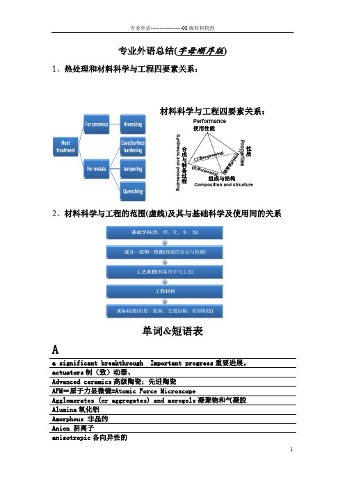
专业外语总结(字母顺序版)1、热处理和材料科学与工程四要素关系:材料科学与工程四要素关系:Performance 使用性能组成与结构合成与制备过程Synthesis and processingComposition and structure性质Properties2、材料科学与工程的范围(虚线)及其与基础科学及使用间的关系单词&短语表Aa significant breakthrough Important progress 重要进展。
actuators 制(致)动器、Advanced ceramics 高级陶瓷;先进陶瓷 AFM =原子力显微镜=Atomic Force MicroscopeAgglomerates (or aggregates) and aerogels 凝聚物和气凝胶 Alumina 氧化铝Amorphous 非晶的 Anion 阴离子anisotropic 各向异性的anode阳极axial projection轴投影BBCC=body-centered cubic体心立方Bioceramics生物陶瓷biodegradable adj. 生物所能分解的Biodegradable systems生物可降解系统biodegradable可生物降解的bio-inspired medical prostheses仿生医学人工器官。
biological tagging生物标记biomedical applications生物医学应用。
biomimetic adj. 仿生的biomolecular single-electron devices生物分子的单电子器件Biotechnology生物技术bivalent/divalent二价的。
bulk acoustic waves BAWs体声波Bulk material 体材料CCapacitor电容器carbon Nanotube碳纳米管Catalyst催化剂Cathode 阴极Cation 阳离子Cement水泥; 接合剂ceramic based composites陶瓷基复合材料Ceramic coating 陶瓷涂层Chemical Composition化学成分Chemical reagent化学试剂civil engineering土木工程Cold isostatic pressing(CIPing) 冷等静压compacting equipment压实设备。

常用金属材料的热膨胀系数详细列表正式版常用金属材料的热膨胀系数材料名称密度(克/厘米3) 灰口铸铁 6.6~7.4 白口铸铁7.4~7.7 可锻铸铁7.2~7.4 铸钢7.8 工业纯铁7.87 普通碳素钢7.85 优质碳素钢7.85 碳素工具钢7.85 易切钢7.85 锰钢7.81 15CrA铬钢7.74 20Cr、30Cr、40Cr铬钢7.82 38CrA铬钢7.8 铬钒、铬镍、铬镍钼、铬锰、硅、铬锰硅镍、硅锰、硅铬钢7.85 铬镍钨钢7.8 铬钼铝钢7.65 含钨9高速工具钢8.3 含钨18高速工具钢8.7 高强度合金钢7.82 轴承钢7.81 不锈钢0Cr13、1Cr13、2Cr13、3Cr13、4Cr13、Cr17Ni2、Cr18、9Cr18、Cr25、Cr28 7.75 0Cr18Ni9、1Cr18Ni9、Cr18Ni9Ti、2Cr18Ni9 Cr14、Cr17 7.7 4-0.3、4-4-4锡青铜8.9 1Cr18Ni11Si4A1Ti 7.52 7铝青铜7.8 19-2铝青铜9-4、10-3-1.5铝青铜7.5 9-4、10-3-1.5铝青铜7.5 10-4-4铝青铜7.46 铍青铜8.3 3-1硅青铜8.47 1-3硅青铜8.6 1铍青铜8.8 0.5镉青铜8.9 0.5铬青铜8.9 1.5锰青铜8.8 5锰青铜8.6 白铜B5、B19、B30、BMn40-1.5 8.9 BMn3-12 8.4 BZN15-20 8.6 BA16-1.5 8.7 BA113-3 8.5 纯铝2.7 防锈铝LF2、LF43 2.68 LF3 2.67 LF5、LF10、LF11 2.65 LF6 2.64 LF21 2.73 硬铝LY1、LY2、LY4、LY6 2.76 LY3 2.73 LY7、LY8、LY10、LY11、LY14 2.8 LY9、LY12 2.78 LY16、LY17 2.84 锻铝LD2、LD30 2.7 LD4 2.7灰铸铁 HT100~HT350 6.6--7.4 白口铸铁 S15、P08、J13等 7.4--7.7 可锻铸铁 KT30-6~KT270-2 7.2--7.4 铸钢 ZG45、ZG35CrMnSi等 7.8 工业纯铁 DT1--DT6 7.87 普通碳素钢 Q195、Q215、Q235、Q255、Q275 7.85 优质碳素钢 05F、08F、15F 10、15、20、25、30、35、40、45、50 7.85 碳素工具钢 T7、T8、T9、T10、T12、T13、T7A、T8A、T9A、T10A、 T11A、T12A、T13A、T8MnA 7.85 易切钢 Y12、Y30 7.85 弹簧钢丝Ⅰ、Ⅱ、Ⅱa、Ⅲ 7.85 低碳优质钢丝 Zd、Zg 7.85 锰钢 20Mn、60Mn、65Mn 7.81 铬钢 15CrA 20Cr、30Cr、40Cr 38CrA 7.74 7.82 7.80 铬钒钢 50CrVA 7.85 铬镍钢 12CrNi3A、20CrNi3A 37CrNi3A 7.85 铬镍钼钢 40CrNiMoA 7.85 铬镍钨钢 18Cr2Ni4WA 7.8 铬钼铝钢 38CrMoA1A 7.65 铬锰硅钢 30CrMnSiA 7.85 铬锰硅镍钢 30CrMnSiNi2A 7.85 硅锰钢 60Si2nMnA 7.85 硅铬钢 70Si2CrA 7.85 高强度合金钢 GC-4、GC11 7.82 高速工具钢 W9Cr4V W18Cr4V 8.38.7 轴承钢 GCr15 7.81 不锈钢 0Cr13、1Cr13、2Cr13、3Cr13、4Cr13 Cr14、Cr17 Cr17Ni2、Cr18、9Cr18、Cr25、Cr28 0Cr18Ni9、1Cr18Ni9 1Cr18Ni9Ti、2Cr18Ni9 Cr18Ni11Nb 1Cr23Ni18、Cr17Ni3Mo2Ti 1Cr18Ni11Si4A1Ti 2Cr13Ni4Mn9 3Cr1 3Ni7Si2 7.7 7.75 7.85 7.857.9 7.9 7.52 8.5 8.0常用金属材料密度表,包括黑色、有色金属材料及其合金材料的密度。


不同孔径的氧化铝陶瓷英文回答:Aluminum Oxide Ceramic with Different Pore Sizes.Aluminum oxide ceramic, also known as alumina ceramic, is a type of advanced ceramic material that is composed primarily of aluminum oxide (Al2O3). It is characterized by its high strength, hardness, wear resistance, and thermal stability. One of the key properties of alumina ceramic is its porosity, which refers to the presence of pores or voids within the material. The pore size of alumina ceramic can vary significantly, depending on the manufacturing process and the intended application.Alumina ceramics with different pore sizes exhibit distinct properties and are used in a wide range of applications. Some of the most common types of alumina ceramics include:Dense alumina ceramic: This type of alumina ceramic has a very low porosity, typically less than 1%. It is characterized by its high strength, hardness, and wear resistance. Dense alumina ceramics are often used in applications where these properties are critical, such as in cutting tools, wear plates, and armor.Porous alumina ceramic: This type of alumina ceramic has a higher porosity, typically between 1% and 50%. It is characterized by its high surface area and permeability. Porous alumina ceramics are often used in applications where these properties are important, such as in filters, catalysts, and membranes.Ultraporous alumina ceramic: This type of alumina ceramic has a very high porosity, typically greater than 50%. It is characterized by its low density and high surface area. Ultraporous alumina ceramics are often used in applications where these properties are critical, such as in thermal insulation, sound absorption, and catalysis.The pore size of alumina ceramic can be controlled byadjusting the manufacturing process. Some of the methods used to control pore size include:Sintering temperature: The sintering temperature affects the grain size and pore size of alumina ceramic. Higher sintering temperatures typically result in larger grain sizes and pores.Doping: Doping alumina ceramic with certain elements, such as magnesium or zirconium, can affect the pore size. Doping can lead to the formation of new phases that have different pore structures.Templating: Templating is a process that uses a sacrificial template to create pores of a specific size and shape. The template is removed after sintering, leaving behind pores with the desired characteristics.The pore size of alumina ceramic has a significant impact on its properties and applications. Some of the key factors that are affected by pore size include:Strength: In general, the strength of alumina ceramic decreases with increasing pore size. This is because pores act as stress concentrators, which can lead to failure under load.Hardness: The hardness of alumina ceramic also decreases with increasing pore size. This is because pores provide a path for crack propagation.Wear resistance: The wear resistance of alumina ceramic decreases with increasing pore size. This is because pores provide a surface for wear particles to lodge and abrade.Thermal conductivity: The thermal conductivity of alumina ceramic decreases with increasing pore size. Thisis because pores act as thermal insulators.Electrical conductivity: The electrical conductivity of alumina ceramic decreases with increasing pore size. This is because pores act as electrical insulators.Due to their unique properties, alumina ceramics with different pore sizes are used in a wide range of applications, including:Cutting tools: Dense alumina ceramics are used in cutting tools because of their high strength, hardness, and wear resistance.Wear plates: Dense alumina ceramics are also used in wear plates to protect surfaces from wear and abrasion.Armor: Dense alumina ceramics are used in armor to provide protection against ballistic impact.Filters: Porous alumina ceramics are used in filters to remove particles from fluids.Catalysts: Porous alumina ceramics are used as catalysts to support catalytic reactions.Membranes: Porous alumina ceramics are used as membranes to separate different components of a fluidmixture.Thermal insulation: Ultraporous alumina ceramics are used in thermal insulation to reduce heat transfer.Sound absorption: Ultraporous alumina ceramics areused in sound absorption to reduce noise levels.Catalysis: Ultraporous alumina ceramics are used as catalysts to support catalytic reactions.中文回答:不同孔径氧化铝陶瓷。

上海恒团工业设备有限公司samboss@From the Expertsfor Advanced CeramicsElectronics ExpertsO ur substrates and many other components are usedthroughout the field of electronics. For example, ceramicheat-sinks provide the right climate for high-power electron-ics. Our components ensure reliable operation in a erospacetechnology, the automotive i ndustry, opto-electronics, mea-surement and control technology and in industry and enter-tainment electronics. CeramTec is one of the leading manu-facturers of these components. Electronics keep the world incontact and in motion – CeramTec advanced ceramics makeit possible that every-thing works the way we expect it to.Medical Products ExpertsAdvanced ceramics are at work in a wide range of medicaldevices, such as litho t ripters and ultrasonic cleaners – orin dental ceramics in the field of dentistry. What’s more,CeramTec bioceramics help maintain and increase the qualityof life, for instance with implant components for artificial hipand knee joints. Biocompatible and e xtremely resilient ad-vanced ceramics enable doctors to provide patients with op-timum care and help patients master the challenges of every-day life again. Today, every minute, a hip joint replacementfeaturing BIOLOX® components is implanted around the world.Automotive Industry ExpertsCeramTec advanced ceramics play a vital role in increasingsafety, cost-effectiveness and comfort in vehicle engineering.Piezoceramic components act as sensors for electronic con-trols and provide them with information on the vehicle’s en-gine running smoothness, position and changes in direction.Electronic components based on ceramic substrates r eact tothis information and control motor management, safety sys-tems like ABS and ASR and release the airbag when neces-sary. In engines heat-resistant ceramic parts like valve compo-nents, backings in the crankshaft housing and componentsfor gasoline and water pumps ensure increased efficiency,less wear and lower noise emission. As a composite MMCMetal Matrix Ceramics open up new horizons in light metalconstruction. And last but not least, modern LED lighting sys-tems with ceramic components significantly improve visibilityand protective ceramics deliver the required safety.Safety and FunctionalityExpertsOften unseen, but always indispensable. Understated through perfect function. Indispensable for perfor m ance, safety andreliability. This is how we interact with CeramTec advanced ceramics every day, often without even noticing them. When wash-ing our hands, making espresso, talking on our cell phones, driving our cars or at the dentist’s office. Everywhere where othermaterials are unable to satisfy the specific demands of special areas of application. Or where high levels of functionality andsafety are required. There are already many areas of application that depend on the unrivaled properties of advanced ceramics.And this material’s potential is far from being exhausted – because CeramTec a dvanced ceramics offer decisive advantages andbenefits for meeting the challenges of the future.Equipment and Mechanical Engineering ExpertsCeramTec advanced ceramics make it possible to securelycontrol processes, reduce emissions and take responsible careof our resources in many areas of chemicals and process en-gineering. Highest wear resistance, temperature resistanceand high corrosion resistance make CeramTec advancedc eramics a reliable alternative to other m aterials in equip-ment, machine and plant engineering. Whether in chemical,environmental or energy technology, in precision engineeringor in metal forming – CeramTec products make a decisivecontribution to increasing the operating life and performancecapability of machines and plants. Metalworking is a goodexample where high-performance machining with our SPKcutting materials and tools offers high process r eliabilityalong with economic and efficient production by decisivelyreducing production times and costs.S A f E T y A n d f u n C T I o n A l I T y• Chemicals and process engineering• Equipment, machine and plant engineering•Energy supply and environmental technology• Metalworking• Recycling and processing• Sanitary fittings• Water treatment• Engine and turbine construction• Sensor and actuator technology• Lighting systems•Electronics and communications technology• Medical devices•Medical implants and prostheticsArEAS of APPlICATIonAdvAnCEd CErAMICSApplication ExpertsD i v i s i o n s a n D s u b s i D i a r i e sComprehensive material, production and application expertise combined with over 100 years of experience make us the lead-ing advanced ceramics specialist for every area of application. As part of an overall, user-oriented organization, independent divisions at CeramTec are responsible for customer support in individual market segments. Every division represents a specific range of services – from development to production all the way to sales. For our customers, this means: proximity, flexible, dynamic partners, a high level of expertise and rapid decisions.The divisions’ Product PortfoliosMechanical ApplicationsComponents from the division make a decisive contribution to extending the service life and performance capability of machines and plants, espe-cially whenever aggressive media and high temperatures are at play. This is in part due to the tremendous wear resistance, temperature insensitiv-ity and high corrosion resistance of the ceramic materials used such as alumina, zirconium oxide, silicon nitride or silicon carbide. To learn more about custom-tailored solutions for industrial applications and machine and plant engineering, speak with the ceramics experts at CeramTec’s Mechanical Applications division.Multifunctional CeramicsSilicate ceramic insulation components, metalized alumina ceramics and expertise in piezo-ceramics make the Multifunctional Ceramics division your system partner for electronics and automotive engineering along with many other areas of application. One of this division’s special areas of expertise includes piezo-ceramics or functional ceramics in the form of advanced piezo-ceramic components, which are indispensable in the areas of sensor and actuator technology.Electronic ApplicationsAs a manufacturer of substrates, circuit carriers and core materials made of alumina and aluminum nitride, the division plays a crucial role in every area of the electronics world. Components are highly versatile and enjoy widespread use in almost all sectors of the industry from automotive engineering to high-performance electronics and optoelectronics, aero-space technology or telecommunications. Depending on the application, components are laser treated, stamped, grooved, dry pressed, extruded or film cast. In addition the division also offers heat-sinks and cooling ele-ments for optimized thermal management and LED technology.Medical ProductsCeramTec‘s Medical Products division has set standards in the field of endoprosthetics since the early 1970s with its BIO LO X ® components. BIOLOX ® components for hip and knee joint replacements have been implanted millions of times worldwide and help patients master the chal-lenges of everyday life again. No other manufacturer’s material is used as often for tribological pairing as BIOLOX ® ceramics. More than 11 million BIOLOX ® components have been implanted since 1974.Chemical ApplicationsThe division manufactures components especially designed to meet the highest demands even under the most difficult working conditions in the chemicals industry, in laboratory and environmental technology and in foundries. Additional application areas include pyrometry, pharma-ceuticals, temperature control technology, galvanic technology and cus-tomized products. The division offers a wide range of ceramic materials for these application areas – including aluminum titanate – paired with comprehensive manufacturing and application engineering expertise anda broad portfolio of forming and processing methods.Mechanical SystemsCeramTec Mechanical Systems division parts and components are used in seal and regulator technology applications throughout the world. From sanitary fixtures and household appliance engineering to automo-tive engineering, ceramic seal and regulator discs and components for pumps, roller bearings, valves and compressors play a key role in ensur-ing smooth, low-maintenance operation of gas and liquid circuits. The Ceramdisc ® and triduon ® brands prove CeramTec competency in sanitary engineering.SPK Cutting ToolsCutting ceramics and inserts made of ceramic cutting materials with matching tools and clamping systems for turning, milling and boring cast iron, hardened steels and materials that are very difficult to machine make the CeramTec SPK Cutting Tools division the expert on productiv-ity. The high-performance ceramic cutting materials, tools and clamping systems are developed and produced in Ebersbach, Germany, where we also design tailor-made products for customers. The division also boasts its own test center, where custom solutions are developed for optimum, cost-effective component machining.The Subsidiarys’ Product PortfoliosEmil MüllerEstablished in 1921 as a metal packaging manufacturer, Emil Müller GmbH began manufacturing stamping and bending parts, garnering the company a permanent position the automotive industry in the years the- reafter. The company headquarters in Wilhermsdorf has been manufactu-ring salt cores exclusively for piston manufacturing for over 25 years now along with other casting components such as engine blocks and oil pans.CeramTec north America Vacuum-tight electrical and optical Ceramaseal ® components.dAI CeramicsCeramic cores for precision casting applications.CeramTec-ETECCeramTec-ETEC is a CeramTec subsidiary headquartered in Lohmar, Germany that offers solutions made from ALO TEC ® advanced ceramics for wear and corrosion protection, ceramic armor for ballistic protection of personnel, vehicles and assets, ALOSLIDE ® inrun track systems for ski jumping events, and PERLUCOR ®transparent ceramics.CeramTec MalaysiaDipping formers for manufacturing rubber gloves for medical, industrial and household use.CeramTec Czech republicSeal and regulator discs for sanitary fittings and devices, components for use in machine and equipment engineering made from RO CAR ® silicon carbide.CeramTec ChinaComponents for textile machinery, laser processing of substrates, seal and regulator discs for fittings and devices.CeramTec KoreaLasered substrates.KoreaCeramTec Korea Suwon City www.ceramtec.kr Malaysia CeramTec MalaysiaSeremban www.ceramtec.my MexicoCeramTec PST Mexiko Puebla PolandCeramTec PST Press + Sintertechnik Gorzyce russiaCeramTec Representation Office Moskauwww.ceramtec.ru SwedenCeramTec Representation Office Gothenburg www.ceramtec.seSpain and Portugal CeramTec Ibérica Vilassar de Mar/Barcelona www.ceramtec.es Czech republicCeramTec Czech Republic Sumperkwww.ceramtec.cz TurkeyCeramTec Representation Office Istanbul.truSACeramTec North America Laurens, SC DAI Ceramics Willoughby, OH Market ExpertsChinaCeramTec Suzhou SuzhouBrazilCeramTec PST Press Sintertécnica Brasil Nova Odessa/Estado de São Paulo .br franceCeramTec Representation Office Pariswww.ceramtec.fr Great BritainCeramTec UK Colyton IndiaCeramTec India Panaji, Goa www.ceramtec.inItalyCeramTec Commerciale Italiana Bergamo www.ceramtec.itl o C AT I o n SPhone +49 7153 611-0/location/plochingen• M edical Products division • M echanical Applications divisionWilhermsdorfPhone +49 9102 9935-35www.emil-mueller-gmbh.deCeramTec Marktredwitz Phone +49 9231 /location/marktredwitz • C hemical Applications division • E lectronic Applications division • M edical Products divisionWith a comprehensive range of products and services, the CeramTec Group satisfies the necessary pre r equisites for playing an active role in international markets. However, this also requires a local presence. In addition to locations in Germany, world-wide subsidiaries, sales organizations, offices and trading partners ensure we are as close to our customers as possible.detailedcontact information is available at:/contact/Piezo-CeramicsThanks to their unique, active properties, p iezo-ceramicshave already made their mark in a wide variety of appli-cation areas. The piezo-ceramic manufacturing processis specifically targeted to give these materials unusualproperties in these combinations, which enable piezo-ceramic components to:•T ransform pressure, expansion or a cceleration into elec-trical energy•T ransform electrical voltage into mechanical action oroscillation• P iezo-ceramics are characterized by their high energydensity and efficiency.Silicon CarbideSilicon carbide materials are extremely light but almostcomparable to diamond in terms of hardness and temp-erature resistance. Special characteristics include:• V ery high hardness•E xcellent corrosion resistance even at very high applica-tion temperatures• T hermal shock resistance• V ery high thermal conductivity (higher than steel)• L ow thermal expansion•H igh wear resistance and very good g liding propertiesSilicon carbide masters corrosion, abrasion and erosionas skillfully as it stands up to frictional wear. Componentsare used in chemical plants, mills, expanders and ex-truders or as nozzles, for example. Silicon carbide’s non-toxicological character makes it ideal for use in the foodand beverage i ndustry. Another typical application areafor silicon carbide components is dynamic sealing tech-nology using friction bearings and mechanical seals, forinstance in pumps and drive systems. Compared to metals,s ilicon carbide enables highly economical s olutions withlonger tool life when used with aggressive, high-temper-ature media. Silicon carbide fittings are also excellentlysuited for use in demanding conditions in chemical pro-duction, energy technology, p aper manufacturing and aspipe system components.Silicon nitrideSilicon nitride materials are perfectly suited for manu-fac-turing mechanically stressed components and for engine-specific appli c ations, especially at high temperatures.They possess remarkable characteristics:• H igh mechanical strength•H igh fracture toughness and impact r esistance• E xcellent wear resistance• G ood thermal conductivity• V ery low thermal expansion• T hermal shock resistanceThese characteristics and its low weight make silicon nitridean excellent material choice for demanding applications.This is why components made of silicon nitride c eramicsare successfully used in various welding processes, for ex-ample.Aluminum nitrideAmong other applications, aluminum n itrides are suitablefor use as electrical i nsulation materials in micro elec-tronics, as resonator materials in aluminum m etal l urgyand in laser technology or as heat e xchangers. They arecharacterized by:• V ery high thermal conductivity• H igh electrical insulation capacity• F avorable temperature cycle resistance• G ood metallization characteristics• L ow thermal expansion• M oreover, aluminum nitrides are used to make substratesfor semi-conductors and high-performance electronics.Metal-Ceramic CompositesComposite materials are required when using light metalcomponents in stress conditions. For composite compo-nents from metal and ceramics (Metal Matrix Composites,MMC or Ceramic Matrix Composites, CMC), a m etallicsubstrate is hardened with ceramic particles for reinforce-ment. The low weight of the metal can thus be combinedwith the resistance of ceramics under tribological, me-chanical and thermal loads. Highly porous ceramic pre-forms are infiltrated by the light metal during the castingprocess and thus assure a seamless transition betweenmetal and ceramic material. Wherever lightweight metal-lic components need to be reinforced or optimized, theuse of metal/ceramic c omposites is a technically and eco-nomically attractive solution.Aluminum TitanateThis material is unique in that it does not expand, even athigh temperatures. Components made of this material canwithstand even the most abrupt temperature changes ofseveral hundred degrees without damage. Aluminum tita-nate is characterized by:• E xcellent thermal shock resistance• H igh thermal insulation• A low Young’s modulus• G ood chemical resistanceThese properties make aluminum titanate especially idealfor use in metallurgical m elting.Silicate CeramicsSilicate ceramics are considered traditional materials andexhibit the following outstanding properties:•V ery good electrical and thermal insulation capacity• H igh temperature cycle resistance•M inimal and/or predefined thermal e xpansion• C orrosion resistanceThese advantages and favorable processing conditionsmake silicate ceramics highly economical solutions for in-sulation components for the electronics industry, for theautomotive sector, for electrical, heating and lightingtechnology and for environmental, thermal, precision andmeasurement technology.Ceramic Materials ExpertsAluminaAlumina in its various levels of purity is p robably the mostimportant oxide ceramic material. CeramTec has a widerange of l ow-density and lightweight materials with avariety of property combinations at its d isposal:•H igh to extremely high mechanical strength• G ood thermal conductivity• H igh corrosion and wear resistance• G ood gliding properties• V ery good electrical insulationZirconium oxideDepending on their crystal structure, z irconium oxides canexhibit pseudo-elastic reactions, thus enabling extremelyhigh component strengths. Alongside their e xcellent tri-bological properties with respect to friction and wear onobjects that move in opposite directions, zirconium oxidesalso demonstrate:• E xtraordinary fracture toughness• H igh wear resistance• H igh corrosion resistance• L ow thermal conductivity• A coefficient of expansion similar to steelThis has helped zirconium oxides gain ground as structuralmaterials for components subject to high stress: Wher-ever wear resistance, corrosion resistance or electrical andthermal insulation are required, zirconium oxide is theideal material in machine and equipment engineering,making it possible to develop new areas of use or replacesteel components.C E r A M I C M AT E r I A l S A n d T H E I r P r o P E r T I E STemperatureresistanceThermal insulation Hardness andwear resistanceBending fractureandcompressivestrengthCorrosion resistanceand biocompatibilityElectric insulationand dielectricstrengthChemical resistance Heat conductivityand thermal shockresistancePiezoelectricityand dynamicsEach application and each ceramic component places individual demands on the capabilities and properties of the material.Therefore, the successful deployment of a product depends above all on selecting the correct material, fine-tuning it and de-signing the component. This is the domain of the ceramic materials experts at CeramTec, who know the optimal advancedceramic material for each requirement profile, and hence the optimal solution to the problem.Monitored processes form the basis for production in which customized prototypes are produced with the same precision and re l iability as standard parts in mass production. Processes like extrusion, pressing, injection and casting help form the raw ceramic mass into complex geometries. O ur furnaces produce high-quality products with fine crystal microstruc-tures under predefined conditions. Taking into consideration the exact amount of unavoidable shrinkage is part of the complex skill set of an expert manufacturer like CeramTec. The final finishing process transforms raw ceramic products into precision components.Quality ExpertsAs a specialist for the development, production and sale of innovative products made from advanced ceramics, CeramTec is committed to uncompromising quality in every area of busi-ness. For CeramTec this means: Being a step ahead today in order to meet our customers’ expectations tomorrow.The book “Technical Ceramics”CeramTec is a partner to the book and provides information, images and suggestions on this topic. The chapters cover a number of subjects including a materials overview, the manu-facturing process, design and technical ceramics in applica-tion, and offer detailed insight into the world of advanced ceramics.Order your copy: /ceramic-materials Systems ExpertsThe only way to create true added value and achieve success is to optimally integrate c eramic components within the system as a whole. This is why the experts at CeramTec do not think in terms of products, but rather in terms of sys-tem solutions. Comprehensive expertise in connection and integration technology creates economical, ceramics-orient-ed solutions for every application. Continuous improvement of functional s afety, optimization of component r esilience, leveraging of savings potential and concentration on a single system supplier makes our ceramics expertise a true advan-tage for our customers.Production ExpertsThe manufacturing and processing methods for advanced ceramics are as varied as the options available for their use and the precisely tuned materials. Every material, and every component design requires individu a lized production tech-nology. As production experts we have had over 100 years to perfect these methods.Experts for the Challenges of the Futuredevelopment ExpertsEach field of application calls for its own d evelopment work and close interaction among users, designers and ceramics e xperts.Basically everything is possible. Comprehensive technology management controls the myriad research and development facilities at CeramTec. Modern methods like design of experi-ments and simulation techniques guarantee rapid develop-ment times.Experienced employees from the research, development and application engineering departments are available right from the start to help you realize your product ideas. Together with your experts we engage ind ialog to define the applica-tion conditions, specification criteria and constructive prereq-uisites and develop economical solutions. O ur innovation management delivers the e xpertise our customers need for advanced solutions.T H E f u T u r E I n S y S T E M S , d E v E l o P M E n T, P r o d u C T I onContinued miniaturization in electronics, innovative surface technologies, trends and developments in the healthcare, neo-ecology (including regenerative energies), mobility and communications technology markets – the challenges of the future are multifaceted and demand innovative solutions. Advanced ceramic materials open up new, undreamed of pos-sibilities for design engineers and de-velopers that take us to new dimensions. The experts at CeramTec help maximize the potential of advanced ceramics. Their extensive experience makes them indispensable partners on the path to new solu-tions and applications. They are specialists whose expertise ensures the greatest safety and probability of success in the development process.• D IN ISO 9001•D IN EN ISO 13485• D IN EN ISO/IEC 17025• ISO TS 16949• DIN EN ISO 50001• DIN EN ISO 14001More at: /qualityQuAlITy MAnAGEMEnT And CErTIfICATIonSCeramTec GmbH CeramTec-Platz 1-973207 Plochingen, DeutschlandPhone: +49 7153 611-0Fax: +49 7153 25421info@ceramtec.de C A 110010 • E N • 1.000 • 1506 • a t i o (3631) • P r i n t e d i n G e r m a n y上海恒团工业设备有限公司samboss@。

[1] Abbas Afkhami, Hasan Bagheri, Tayyebeh Madrakian, Alumina nanoparticles grafted with functional groups as a new adsorbent in efficient removal of formaldehyde from water samples, Desalination 281 (2011) 151–158.[2] Haibao Huang,Dennis Y. C. Leung and Daiqi Ye,Effect of reduction treatment on structural properties of TiO2supported Pt nanoparticles and their catalytic activity for formaldehyde oxidation, Journal of Materials Chemistry J. Mater. Chem. 2011 /21/ 9647.[3] YOSHIO NAKANOM, KENJI TAKESHITA and TOSHIRO TSUTSUMI,ADSORPTION MECHANISMOF HEXA V ALENT CHROMIUMBY REDOX WITHIN CONDENSED-TANNIN GEL,Wat. Res. V ol. 35, No. 2, pp. 496±500, 2001.[3] A. Hayashi ,Y. Fujimoto, Y. Ogawa, H. Nakayama, M. Tsuhako,Adsorption of gaseous formaldehyde and carboxylic acids by ammonium-ion-exchanged α-zirconium phosphate , Journal of Colloid and Interface Science 283 (2005) 57–63.[4]Kyung Jin Lee a, Nanako Shiratorib, Gang Ho Lee b, Jin Miyawakib, Isao Mochida b,Seong-Ho Yoon b, Jyongsik Jang a,Activated carbon nanofib er produced from electrospun polyacrylonitrile nanofiber as a highly efficient formaldehyde adsorbent, CARBON 48 (2010) 4248 – 4255.[5] Wang Xiaoyan, Wang Huixiang*, Wang Shaoli,Ambient formaldehyde and its contr and OH radical in a rural area, Atmospheric Environment 44 (2010) 2074e2078.[6] Adrian M. T. Silvaa Isabel M. Castelo-Brancoa, Rosa M. Quinta-Ferreiraa, Janez Levec,Catalytic studies in wet oxidation of e%uents from formaldehyde industry, Chemical Engineering Science 58 (2003) 963 – 970.[7] Haiqin Rong , Zhenyu Ryu , Jingtang Zheng , Yuanli Zhang,Effect of air oxidation of Rayon-based activated carbon fibers on the adsorption behavior for formaldehyde, Carbon 40 (2002) 2291–2300.[8] A. Karantonis , D. Koutsaftis, N. Kouloumbi, Bistability, oscillations and bifurcations of the electrocatalytic oxidation of HCHO on Pt, Chemical Physics Letters 422 (2006) 78–82.[9]LI Jing , LI Zhong , LIU Bing , XIA Qibin and XI Hongxia, Effect of Relative Humidity on Adsorption of Formaldehyde on Modified Activated Carbons, Chinese Journal of Chemical Engineering, 16(6) 871ü875 (2008).[10] R.B. de Lima, M.P. Massafera, E.A. Batista, T. Iwasita, Catalysis of formaldehyde oxidation by electrodeposits of PtRu, Journal of Electroanalytical Chemistry 603 (2007) 142–148.[11] Afsaneh Safavi , Norouz Maleki, Fatemeh Farjami, Elaheh Farjami, Electrocatalytic oxidation of formaldehyde on palladium nanoparticles electrodeposited on carbon ionic liquid composite electrode, Journal of Electroanalytical Chemistry 626 (2009) 75–79.[12] Zhe Wang , Zan-Zan Zhu, Jin Shi, Hu-Lin Li, Electrocatalytic oxidation of formaldehyde on platinum well-dispersed into single-wall carbon nanotube/polyaniline composite film, Applied Surface Science 253 (2007) 8811–8817.[13] Xiao-Gang Zhang, Yasushi Murakami, Kiyochika Yahikozawa and Yoshio Takasu, Electrocatalytic oxidation of formaldehyde on ultrafine palladium particles supported on a glassy carbon, Electrochimica Acta, V ol. 42, No. 2, 223-227, 1997.[14] V. Selvaraj,A.NirmalaGrace ,M.Alagar, Electrocatalytic oxidation of formic acid and formaldehyde on nanoparticle decorated single walled carbon nanotubes, Journal of Colloid and Interface Science 333 (2009) 254–262.[15] Algirdas Vaškelis, Eugenijus Norkus, Irena Stalnionien˙ e, Giedrius Stalnionis, Effect of theCu electrode formation conditions and surface nano-scale roughness on formaldehyde anodic oxidation, Electrochimica Acta 49 (2004) 1613–1621.[16] Bingye Xu , Jing Shang , Tong Zhu , Xiaoyan Tang, Heterogeneous reaction of formaldehyde on the surface of -Al2O3 particles, Atmospheric Environment 45 (2011) 3569e3575.[17] Meichao Li, Wuyang Wang, Chun’an Ma , Wanxia Zhu, Enhanced electrocatalytic activity of Pt nanop articles modified with PPy-HEImTfa for electrooxidation of formaldehyde, Journal of Electroanalytical Chemistry 661 (2011) 317–321 .[18] Somjate Photong, Virote Boonamnuayvitaya,Enhancement of formaldehyde degradation by amine functionalized silica/titani a films,Journal of Environmental Sciences 21(2009) 1741–1746.[19]Hua Tian,Junhui He,Xiaodan Zhang,Li Zhou a,Donghui Wang,Facile synthesis of porous manganese oxide K-OMS-2 materials and their catalytic activity for formaldehyde oxidation,Microporous and Mesoporous Materials 138 (2011) 118–122.[20]Yang Xuzhuang Shen Yuenian Yuan zhangfu Zhu Huaiyong,Ferric ions doped 5A molecular sieves for the oxidation of HCHO with low concentration in the air at moderate temperatures,Journal of Molecular Catalysis A: Chemical 237 (2005) 224–231.[21]V.A. de la Pen O’Shea, M.C. A ´ lvarez-Galva , J.L.G. Fierro, P.L. Arias, Influence of feed composition on the activity of Mn and PdMn/Al2O3catalysts for combustion of formaldehyde/methanol, Applied Catalysis B: Environmental 57 (2005) 191–199.[22] XU BingYe, ZHU Tong, TANG XiaoYan& SHANG Jing, Heterogeneous reaction of formaldehyde on the surface of TiO2 particles, December 2010 V ol.53 No.12: 2644–2651. [23] Renhu Wang ,Junhua Li, OMS-2 Catalysts for Formaldehyde Oxidation: Effectsof Ce and Pt on Structure and Performance of the Catalysts, Catal Lett (2009) 131:500–505DOI 10.1007/s10562-009-9939-5.[24] Jiangli Geng , Yingpu Bi , Gongxuan Lu, Morphology-dependent activity of silver nanostructures towards the electro-oxidation of formaldehyde, Electrochemistry Communications 11 (2009) 1255–1258.[25] Mara Terumi Fukunaga , Jos´ e Roberto Guimar, Rodnei Bertazzoli, Kinetics of the oxidation of formaldehyde in a flow electrochemical reactor with TiO2/RuO2 anode, Chemical Engineering Journal 136 (2008) 236–241.[26] Virote Boonamnuayvitayaa,Srisuda Sae-ungb, Wiwut Tanthapanichakoonc, Preparation of activated carbons from coffee residue for the adsorption of formaldehyde, Separation and Purification Technology 42 (2005) 159–168.[27] Guohua Zhao, Yiting Tang, Rui Chen, Rong Geng, Dongming Li, Potential and current oscillations during formaldehyde oxidation on platinum particles dispersed in three-dimensional pore networks of TiOx/Ti, Electrochimica Acta 53 (2008) 5186–5194.[28] Chunming Jianga, Hui Chena, Cheng Yua, Song Zhanga, Baohong Liua, Jilie Kong, Preparation of the Pt nanoparticles decorated poly(N-acetylaniline)/MWNTs nanocomposite and its electrocatalytic oxidation toward formaldehyde, Electrochimica Acta 54 (2009) 1134–1140. [29] P. Glarborga, M.U. Alzuetab, K. Kjærgaarda, K. Dam-Johansena, Oxidation of formaldehyde and its interaction with nitric oxide in a flow reactor, Combustion and Flame 132 (2003) 629–638.[30] Jiaxi Peng , Shudong Wang, Performance and characterization of supported metal catalysts for complete oxidation of formaldehyde at low temperatures, Applied Catalysis B: Environmental73 (2007) 282–291.[31] Yuejuan Zhang , Jianjun Yi, Qinghong Xu, Studies on adsorption of formaldehyde in zirconium phosphateeglyphosates, Solid State Sciences 13 (2011) 54e58.[32] P.OLrvr,t L.0.S.BULH~ES,J.-M.LI’ZGER,F.HAHN,B.BEDEN and C. LAMY, THE ELECTROOXIDA TION OF FORMALDEHYDE ON t(lOO) AND Pt(ll0) ELECTRODES IN PERCHLORIC ACID SOLUTIONS, 001~4686(%)00387-8.[33] Kinga Go ra-Marek , Jerzy Datka, The transformation of formaldehyde on CoZSM-5 zeolites, Catalysis Today 137 (2008) 466–470.[34] Haichao Liu, Patricia Cheung, and Enrique Iglesia, Structure and support effects on the selective oxidation of dimethyl ether to formaldehyde catalyzed by MoOx domains, Journal of Catalysis 217 (2003) 222–232.[35] Jih-Mirn Jehng , Wan-Chen Tung , Chao-His Huang , Israel E. Wachs, Structural characteristics and reactivity properties of the tantalum modified mesoporous silicalite (MCM-41) catalysts, Microporous and Mesoporous Materials 99 (2007) 299–307.[36] 陆洪彬冯春霞李文丹杨凤玲焦宝祥, TiO2修饰空心玻璃微珠隔热涂料的制备及其性能表征, 化工新型材料第38卷第8期010年8月.[37] Galina Ya. Popova, Tamara V. Andrushkevich, Yurii A. Chesalov,Valentin N. Parmon, Transient response study of the formaldehyde oxidation to formic acid on V–Ti–O catalyst: FTIR and pulse study, Journal of Molecular Catalysis A: Chemical 268 (2007) 251–256.[38] 谢昌平,王曙光,周彩楼,雅菁,陈倩,TiO2 光触媒降解甲醛影响因素的分析, 天津城市建设学院学报第17卷第2期2011 年6月.[39] 徐敏, 何满潮, 王岩, 闵延琴, 武成杰, TiO2/ACF 复合材料吸附-光催化降解甲醛的实验研究, 中国安全生产科学技术第4卷第2 期2008 年4月.[40] Yang Li, Min Shao , Sihua Lu , Chih-Chung Chang , Purnendu K. Dasgupta , V ariations and sources of ambient formaldehyde for the 2008 Beijing Olympic games, Atmospheric Environment 44 (2010) 2632e2639.[41]李振海,徐梦洁,叶青,王育华, 掺氮TiO2- 活性炭复合吸附材料的制备与性能, 同济大学学报(自然科学出版) 第38 卷第12 期2010 年12 月.[42]李一诺,陶冶,王倞,杜鸿基,车载型纳米光催化空气净化器的研制,JIE NENG YU HUAN BAO 2005.NO.6.月刊.[43]卢敬霞,张彭义,何为军,臭氧光催化降解水中甲醛的研究,环境工程学报第4卷第一期2010年1月.[44] 饶荣水Rong-shui Rao 崔文勇Wen-yong Cui 李开元Kai-yuan Li周泽Ze Zhou肖建军Jian-jun Xiao刘凌Ling Liu, 不同基材对二氧化钛光催化降解甲醛影响的实验研究(Experimental Investigation on Influence of Different Substrateof TiO2 on Photocatalysis Degradation of Formaldehyde), 配件与材料.[45]赵胜强,李振海,俆梦洁,掺氮TiO2活性炭复合材料室内空气净化器,现场与发展制冷技术2010年第4期.[46]叶剑张瑞丰琳熙, 大尺寸大孔径TiO2 /SiO2 光催化剂的制备及甲醛去除研究,环境工程学报第5 卷第7 期2 0 1 1 年7 月.[47] 王文超, 王英, 王丽娜, 二氧化锰脱除甲醛机理的探讨,有色矿冶第24 卷第1 期2008 年2 月.[48] 董莹,寇江勇,陈芳, 光触媒喷液类产品光催化活性快速评价方法研究, 纳米科技第6 卷第5期2009年10月.[49] 王黎明,沈勇,张惠芳,丁,颖,蔡再生,改性纳TiO2光触媒织物整理剂多功能整理效果研究, 印染助剂第8 卷第 2 期2011 年 2 月.[50] 罗俊旋,曾伟华,徐游,汤皎宁,胡军辉, 光催化还原法制备铜基二氧化钛(Cu/TiO2), 广东化工2011年第6 期第38卷总第218期.[51] 齐虹,孙德智,迟国庆, 光催化降解甲醛的影响因素及动力学研究, 哈尔滨工业大学学报第38卷第7期2006年7月.[52]许涛,光催化净化室内空气技术的应用, 山西化工第23 卷第2期2003 年5月.[53] 孔德双谷昌军孔令仁, 光催化三维蜂窝陶瓷网净化室内空气的研究, 环境工程学报, 第2卷第6期2 0 0 8 年 6 月.[54] 丁云飞王高飞陈延东周毅, 光催化型过滤器分解有机化合物的实验研究, 建筑热能通风空调Building Energy&Environment, 第25 卷第 5 期2006 年10 月.[55] 古政荣, 陈爱平, 戴智铭,古宏晨,陶国忠, 活性炭-纳米二氧化钛复合光催化空气净化网的研制, 华东理工大学学报Journ al of East Chin a Universit y of Science an d T echnology Vol . 26 No. 42000- 08.[56] 胡军陈建华贾铭椿, 活性碳纤维负载TiO2去除低浓度甲醛气体的实验研究, 武汉理工大学学报JournalofWuhanUniversityofTechnology第35卷第4期2011年8月.[57] 何彦刚,黎钢, 甲醛分解的研究新进展.[58] 张淑霞王晓文高亚辉巩卫东杨蕊蕊孙亚真, 甲醛检测方法研究进展, 食品工程科学技术.[59] 张旭刘蔽蔽王代民, 净醛内墙乳胶漆的研制,广东嘉宝莉化工有限公司.[60]张运乾,刘震炎,高鹏,施建伟,上官文峰, 集中空调系统中光催化降解甲醛的实验研究,暖通空调2 0 0 6年第3 6卷第9期技术交流.[61] 张淑娟,黄耀棠, 利用植物净化室内甲醛污染的研究进展, 生态环境学报2010, 19(12): 3006-3013 Ecology and Environmental Sciences.[62] 贺洋郑水林沈红玲, 纳米TiO2/海泡石复合粉体的制备及光催化性能研究, 非金属矿Non-Metallic Mines第33卷第1期2010年1月.[63] 陈小泉, 沈文浩, 纳米TiO2晶体胶体在居室净化中的应用研究,环境科学与技术Environmental Science & Technology第31 卷第10 期2008 年10 月.[64] 陈雯雯,综述; 邵华,审校, 空气中甲醛快速简易检测方法的研究进展, 中国卫生检验杂志2008年4月第18卷第4期C h i nese Jou rnal ofH ea l th Laboratory Technol ogy , Apr 2008; V ol 18No 4.[65] 徐辉张淼, 居住环境空气中甲醛污染的控制与治理,科技风.[66] 李双妹韩红梅, 浅析室内甲醛的危害、预防及治理技术, 潍坊教育学学报第19卷第4期2006年第4期.[67] 何运兵,纪红兵,王乐夫, 室内甲醛催化氧化脱除的研究进展, 化工进展2007年第26卷第8期1104.[68] 张兴朱琨李丽, 室内甲醛检测方法及防治措施研究进展, 环境与健康.[69] 李巍朱永法, 气相色谱对气相甲醛的快速测定,研究报告2002年第五期.[70] 崔耀军王浩张国宣,纳米TiO2涂料光催化降解室内甲醛气体的研究,河南金丹乳酸科技有限公司.[71] 刘春丽章亚东,室内甲醛污染治理的研究进展, 江苏化工科技进展第35卷第1期2007年2月.[72]张俊敏,朱忠其,刘强,张瑾,柳清菊,室内甲醛污染治理技术的研究进展,材料导报2008年5月第22卷专辑X.[73] 李丽,朱琨,室内空气污染现状及防治措施, 内蒙古环境科学第20卷第2期2008年4月.[74] 李玉华, 王琨,孙丽欣, 张力为,室内空气甲醛污染控制研究, 哈尔滨工业大学市政环境工程学院,哈尔滨150090.[75] 刘杨灏,余倩,李聪,林鑫,张小庆,余林,武伦福, 室内甲醛净化处理的研究进展, 广东化工2011年第6期第38卷总第218期.[76] 范睿,室内空气中甲醛的检测及防治技术研究进展, 沧州师范专科学校学报第2 7卷第1期2 011年3月.[77]段云海, 王琨, 李玉华, 刘瑶瑶, 室内空气中甲醛和苯系物检测与净化, 第32卷第6期2007年6月环境科学与管理.[78] 唐幸福, 黄秀敏, 邵建军, 刘俊龙, 李永刚, 徐奕德, 申文杰, 氧化锰八面体分子筛纳米棒的合成及其催化甲醛低温氧化性能, 催化学报第27 卷第 2 期Vol . 27 No. 2.[79]贺世权,阳必飞,申伟杰,氧化模块除甲醛技术在空调上的应用,青岛海尔空调有限公司.[80] 范红玉, 李小松, 刘艳霞, 刘景林, 赵德志, 朱爱民,循环的存储-放电等离子体催化新过程脱除室内空气中甲苯, 第62 卷第7 期化工学报Vol 62 No 7 2011年7月.[81] 黄翔王与娟樊丽娟狄育慧吴志湘西安工程大学,新型功能性空气过滤材料研究进展,暖通空调HV &AC 2009 年第39 卷第1 期.[82] 张博, 王明连, 耿彦生, 张青, 王庆亮,我国空气净化消毒方法研究进展, 环境与健康杂志2007 年9 月第24 卷第9 期J Environ Health, September 2007, V ol.24, No.9. [83] 章骅, 周述琼, 但德忠,室内污染控制技术研究进展, 中国测试技术第31 卷第6期2005 年11月.[84]。

两步法制备多孔钛酸铝陶瓷冯厚坤;张长森;于方丽;冯桢哲;张建利【摘要】Porous aluminum titanate ceramic was prepared by using starchas pore forming agent and Al2TiO5 powder as the main raw material.TheAl2TiO5 powder was synthesized before hand by sol-gel method andsolid-state reaction me.The effects of Al2TiOs powder and additives on the bending strength,apparent porosity,phase composition and microstructure of the porous ceramics were studied.The results show that with 5% MgO and 10% SiO2 added,the apparent porosity of the porous ceramics is 35.18%and bending strength 22.68MPa.The addition of compound additivescould more effectively inhibit the decomposition of Al2TiO5 at high temperature and improve the bending strength of the ceramics than the addition of single.%以溶胶-凝胶法与固相反应法制备的Al2 TiO5粉体为主要原料,采用淀粉为造孔剂,制备多孔钛酸铝陶瓷.研究了Al2 TiO5粉体及添加剂对多孔陶瓷的抗折强度、显气孔率、物相组成和显微结构等的影响.结果表明,添加5%MgO和10% SiO2制备的多孔钛酸铝陶瓷的抗折强度为22.68MPa,显气孔率为35.18%;加入复合添加剂比单一添加剂更有效地抑制Al2 TiO5的高温分解,提高陶瓷的抗折强度.【期刊名称】《材料科学与工程学报》【年(卷),期】2017(035)003【总页数】4页(P419-422)【关键词】溶胶-凝胶法;固相反应法;钛酸铝;添加剂;多孔陶瓷【作者】冯厚坤;张长森;于方丽;冯桢哲;张建利【作者单位】盐城工学院材料工程学院,江苏盐城224051;江苏大学材料科学与工程学院,江苏镇江212000;盐城工学院材料工程学院,江苏盐城224051;盐城工学院材料工程学院,江苏盐城224051;盐城工学院材料工程学院,江苏盐城224051;江苏大学材料科学与工程学院,江苏镇江212000;盐城工学院材料工程学院,江苏盐城224051;常州大学材料科学与工程学院,江苏常州 213164【正文语种】中文【中图分类】TQ174.75随着现代金属冶炼、航空航天及汽车工业等领域的迅猛发展,对陶瓷材料性能的要求也不断提高,尤其在耐高温和抗热震性等方面。

固体酸催化剂SSA催化合成尼泊金乙酯庄凰龙;王强;郭涓【摘要】以磺化硅胶( SSA)为催化剂催化合成尼泊金乙酯,考察SSA用量,反应时间、反应温度和醇酸摩尔比对尼泊金乙酯产率的影响,实验结果表明尼泊金乙酯的最佳反应条件为SSA用量0.3 g,反应时间4 h,反应温度为回流温度,醇酸比为41。
尼泊金乙酯的收率为86.7%以SSA作为合成尼泊金酯的催化剂具有产率高,操作简便,可重复使用,具有较好的应用前景。
%Silica sulfuric acid was used as the catalyst for synthesis of nipagin ester. The efects of SSA amounts, reaction time, reaction temperature and molar ratio of alcoholto acid on the product yield were investigated. The experimental results showed that the optimum conditions were as follows:reaction time 4 h at reflux temperature, the molar ratio of alcohol to acid 41, the amounts of SSA 0.3 g. The yield of nipagin ester was 86.7%. The synthesis of Nipagin ester using SSA as catalyst, is an easy way with high productivity and repeated utilization, has better application prospect.【期刊名称】《广州化工》【年(卷),期】2015(000)004【总页数】3页(P85-86,155)【关键词】催化合成;磺化硅胶;尼泊金乙酯【作者】庄凰龙;王强;郭涓【作者单位】宁德师范学院,福建宁德 350021;宁德师范学院,福建宁德350021;宁德师范学院,福建宁德 350021【正文语种】中文【中图分类】O625.31+1尼泊金酯也叫对羟基苯甲酸酯,是国际上公认的广谱性高效防腐剂,由于它具有酚羟基结构,所以抗细菌性能比苯甲酸、山梨酸都强,对常见的霉菌、酵母都具有良好的抑制作用[1],并且其毒性低[2-3],在人体内易水解,已在食品、饮料、化妆品和医药行业有着广泛的应用。

CERAMICSINTERNATIONALAvailable online at Ceramics International 42(2016)3631–3637Effects of excess boron and B 4C addition on combustion synthesisof NbB 2/mullite compositesC.L.Yeh n ,C.C.ChouDepartment of Aerospace and Systems Engineering,Feng Chia University,100Wenhwa Road,Seatwen,Taichung 40724,TaiwanReceived 12October 2015;received in revised form 3November 2015;accepted 5November 2015Available online 12November 2015AbstractNbB 2/mullite composites were fabricated by self-propagating high-temperature synthesis (SHS)involving aluminothermic reduction of Nb 2O 5.Amorphous boron and B 4C were adopted as the source of boron in two reaction systems composed of Nb 2O 5–B –Al –SiO 2and Nb 2O 5–B –B 4C –Al –SiO 2.The effects of excess boron and B 4C addition were studied on the combustion characteristics and product compositions.Due to suf ficiently high combustion temperatures,the B-adopted samples were subjected to not only aluminothermic but also borothermic reactions.Because the latter caused a considerable loss of boron,the B-adopted sample required excess boron of about 24mol%to convert boride phases into NbB 2.Besides providing boron,B 4C was found to reduce the combustion exothermicity and then to suppress the borothermic reaction for the B/B 4C-containing sample.Consequently,a small amount of excess boron of 2.6mol%was suf ficient for the B/B 4C-adopted sample to produce NbB 2and mullite with trivial minor phases.&2015Elsevier Ltd and Techna Group S.r.l.All rights reserved.Keywords:A.Powders:solid state reaction;D.Borides;D.Mullite;B 4C;Combustion synthesis1.IntroductionMullite is a stable crystalline phase in the aluminosilicate system under the atmospheric pressure and its composition ranges from 3Al 2O 3Á2SiO 2(3:2mullite)to approximately 2Al 2O 3ÁSiO 2(2:1mullite).Mullite of the 3:2composition has been mostly studied,due to the combination of many exceptional properties including high melting point of about 18501C,good chemical and thermal stability,high creep resistance,low thermal expansion coef ficient,low dielectric constant and transmittance to infrared [1,2].These properties render mullite ceramics fit for high-temperature structural,electronic packing and optical applications [1,2].For the improvement in fracture toughness,flexural strength,and thermal shock resistance,mullite-based composites rein-forced by ZrO 2and Al 2O 3have been broadly investigated [3–7].Recently,mullite with other reinforcements such asTiC,SiC,TiB 2,TaB 2,and MoSi 2became the focus of attention [8–13].A variety of processing techniques with different starting materials have been employed to prepare mullite in the monolithic and composite forms,including sol –gel method [14,15],slip casting [3,4],reaction sintering [5,16],arc plasma melting [17],spark plasma sintering (SPS)[18,19],solution combustion synthesis [20,21]and solid phase combustion synthesis in the modes of self-propagating high-temperature synthesis (SHS)[10–12]and thermal explosion [13].The SHS fabrication route is one of the emerging cost-effective tech-nologies and is merited by high energy effectiveness,short processing time,high product purity,and simple facilities [22].A number of advanced materials,including carbides,borides,nitrides,silicides,and intermetallics such as aluminides and titanides,have been produced by the SHS method [22–24].When incorporated with the thermite reaction using Al as the reducing agent,the SHS process represents an in situ approach of preparing ceramic and intermetallic matrix composites reinforced by Al 2O 3[25,26]./locate/ceramint/10.1016/j.ceramint.2015.11.0280272-8842/&2015Elsevier Ltd and Techna Group S.r.l.All rights reserved.nCorresponding author.Tel.:þ886424517250x3963;fax:þ886424510862.E-mail address:clyeh@.tw (C.L.Yeh).It have been proved that once the heat released from thecombustion reaction is sufficient to support endothermicmullitization between Al2O3and SiO2,the production ofmullite-based composites is feasible in the SHS fashion.Withthe addition of SiO2into a thermite mixture of TiO2–B2O3–Al, Zaki[10]produced TiB2/mullite composites by the SHSprocess from the powder compacts under a preheating tem-perature ing the same technique with preheatingat6001C,Zaki et al.[11]synthesized TiB2/ZrO2/mullitecomposites from the samples made up of the ZrSiO4–TiO2–B2O3–Al powder blend.By taking advantage of highly-energetic aluminothermic reduction of Ta2O5and B2O3,Yeh and Kao[12]attained self-sustaining combustion to produce TaB/TaB2/mullite composites with no prior heating on the sample compacts of Ta2O5–B2O3–Al–SiO2.Due to relatively weak exothermicity of the MoO3–SiO2–Al system,however, formation of the MoSi2/mullite composite was conducted in the mode of thermal explosion with a resistance coil placed around the sample[13].For the preparation of transition metal borides by combus-tion synthesis,fabrication routes such as direct combustionbetween the metal and boron[27],borothermic reduction ofmetal oxides[28],and boron carbide reduction of metal oxides[29]have been explored.Transition metal borides are attractivefor high-temperature structural applications and serve as goodreinforcements in various materials,due to their uniquephysical and chemical properties,including high melting point,high hardness,high elastic modulus and mechanical strength,excellent chemical and oxidation stability,and good wear andcorrosion resistance[30].This study aims at combustion synthesis of the NbB2/mullitecomposite in the SHS mode.Instead of using B2O3as thesource of boron,this study employs amorphous boron andboron carbide(B4C).This is mainly because B2O3has a highvapor pressure and evaporation of B2O3becomes significant attemperatures as low as about12001C[31].Besides boron andB4C,the raw materials include Nb2O5,Al,and SiO2.Thespecific objectives of this work are to examine the degree ofamorphous boron involved in borothermic reduction of Nb2O5and its consequences,and to evaluate B4C as an additive infacilitating the formation of NbB2.In addition,this studyinvestigates evolution of mullite from the SHS reaction andcharacterizes the self-sustaining combustion process.2.Experimental methods of approachThe starting materials of this study are niobium oxide(Nb2O5)(Strem Chemicals,o45μm,99.9%),amorphous boron(Noah Technologies Corp.,o1μm,92%),boron carbide(B4C)(Showa Chemical,o10μm,99.5%),Al(Showa Chemical Co., o45μm,99.9%),and SiO2(Strem Chemicals,99%).The reaction system(1)adopts amorphous boron as the only source of boron to mix with Nb2O5,SiO2and Al under the stoichiometry of 1.8Nb2O5þx Bþ6Alþ2SiO2with x¼7.2–9.5.An exact stoichiometric reaction is established at x¼7.2of boron,as expressed in the following.1:8Nb2O5þ7:2Bþ6Alþ2SiO2-3:6NbB2þ3Al2O3U2SiO2ðÞðR1ÞThis study paid particular attention to combustion reactions with excess boron.One is because during the SHS process borothermic reduction of Nb2O5could occur and lead to the loss of boron in the gaseous BO form[32,33].The other is to compensate for amorphous boron with inherently low purity of about92%.In addition to elemental boron,the reaction system (2)utilizes B4C and is formulated under the composition of 1.8Nb2O5þy Bþ0.5B4Cþ6Alþ2SiO2with y¼5.2–6.0.The content of boron at y¼5.2represents the stoichiometric amount for the reaction system(2).Likewise,the samples with extra boron were considered.As an effective substituent for expensive boron,B4C has been used for formation of transition metal borides by combustion synthesis[34,35]. Another important role played by B4C in the synthesis process is to reduce the extent of borothermic reduction,because of preferential carbothermic reduction of the metal oxide[36,37]. It should be noted that the addition of B4C causes a decrease in the combustion temperature,but B4C requires a temperature of about14501C to complete the reduction of metal oxides[29]. Therefore,the reaction temperature higher than14501C was the most important criterion considered by this study to determine the content of B4C.In addition,the amount of B4C was targeted to provide approximately25%of boron needed for the reaction system(2).Sample compacts in a cylindrical shape with7mm in diameter,12mm in length,and55%in relative density were obtained by pressing the well-mixed reactant powders.The synthesis experiments were conducted under high-purity (99.99%)argon of0.15MPa.The combustion propagation rate and combustion temperature were precisely measured.Details of the experimental techniques were reported elsewhere[35].3.Results and discussionbustion front velocity and combustion temperature Two typical combustion series are illustrated in Fig.1(a)and(b)for powder compacts of the reaction systems(1)and(2)with boron of x¼9.5and y¼5.5,respectively.According to Fig.1(a)and(b),a well-defined combustion front propagat-ing in a self-sustaining manner was established,which con-firms sufficient exothermicity for both reaction systems.It is believed that aluminothermic reduction of Nb2O5(withΔH¼–536kJ/mol of Al2O3)is the most important heat-releasing step to initiate the sequence of synthesis reactions.Formation of NbB2(ΔH f¼–175.3kJ/mol)is also exothermic.However, mullitization between Al2O3and SiO2is an endothermic process and absorbs energy of67.6kJ/mol of mullite[10]. Moreover,Fig.1(a)shows that the as-synthesized product exhibits some cracks formed during the SHS process.When compared with that obtained from the B-adopted samples,the product synthesized from the B4C-containing sample of Fig.1C.L.Yeh,C.C.Chou/Ceramics International42(2016)3631–3637 3632(b)is more cohesive and denser.This implies that B 4C enhances the sinterability of the product.It is useful to note that B 4C was proved to be a good sintering aid to improve the sinterability of the powders and to facilitate the densi fication of transition metal borides [31].Fig.2presents the effect of excess boron on the flame-front propagation velocity (V f )of the powder compact.The increase of boron substantially decreased the combustion velocity from 6.5to 3.3mm/s for the B-adopted samples of the reaction system (1).Excess boron was partly to compensate for amorphous boron with relatively low purity.In part,additional boron was to redeem the loss of boron in the form of gaseous BO generated from borothermic reduction of Nb 2O 5,as expressed in (R2)[33].0:2Nb 2O 5ðs Þþ1:8B ðs Þ-0:4NbB 2ðs ÞþBO ðg ÞðR2ÞThe reaction (R2)is an incomplete redox reaction and takes place in an endothermic fashion with ΔH ¼309.8kJ/mol of BO.The occurrence of borothermic reduction as (R2)could weaken the combustion exothermicity,and therefore,decelerated the combustion wave.When compared with the reaction system (1),the B/B 4C-adopted sample exhibited a lower flame-front speed that decreased from 4.4to 3.1mm/s with increasing boron content.It should benoted that B 4C participated simultaneously in both borothermic and carbothermic reactions,as shown in (R3)[38].Nb 2O 5ðs ÞþB 4C ðs Þ-2NbB 2ðs ÞþCO ðg Þþ2O 2ðg ÞðR3ÞFig.1.Recorded SHS series of images illustrating self-sustaining combustion throughout (a)a B-adopted sample of x ¼9.5and (b)a B/B 4C-adopted sample of y ¼5.5.Excess Amount of Elemental Boron (mol%)5101520253035F l a m e -F r o n t V e l o c i t y , V (m m /s )2345678Fig.2.Effects of excess boron and B 4C addition on flame-front velocity of powder compacts.C.L.Yeh,C.C.Chou /Ceramics International 42(2016)3631–36373633The reaction (R3)is extremely endothermic with ΔH ¼1501kJ/mol of CO.A small amount of B 4C involved in the SHS process could signi ficantly reduce the combustion exothermicity and lowered the combustion wave speed.Moreover,to some extent the reaction (R2)could be inhibited as the combustion temperature was decreased by B 4C addition.Fig.3plots four combustion temperature pro files to evaluate the reaction exothermicity of the samples with excess boron and B 4C addition.The abrupt rise in temperature signi fies rapid arrival of the combustion wave and the peak value corresponds to the combustion front temperature.After the passage of the combustion wave,an appreciable drop in temperature is a consequence of heat loss to the surroundings.For the B-adopted samples of the reaction system (1),Fig.3shows that the increase of boron from x ¼7.2to 9.0leads to a decrease in the combustion front temperature from 1726to 16501C.This is consistent with dependence of the flame-front velocity on the boron content.On the other hand,for the reaction system (2)the B/B 4C-adopted samples of y ¼5.2and 6.0exhibited their respective peak combustion temperatures of 1570and 15281C.This con firms the cooling effect induced by B 4C.As mentioned above,the decrease of combustion temperatures by B 4C addition could suppress the degree of the borothermic reaction as (R2).Therefore,the loss of boron could be lessened for the B/B 4C-adopted sample.3.2.Product composition and microstructureFor the reaction system (1),the XRD spectra depicted in Fig.4verify that mullite was successfully formed from redox-produced Al 2O 3and pre-added SiO 2.Besides mullite,niobium borides exist in three phases,NbB,Nb 3B 4,and NbB 2.The presence of NbB and Nb 3B 4signi fies a lack of boron to convert into NbB 2.Especially for the B-adopted sample of x ¼7.2,Fig.4(a)shows that NbB is the dominant boride.With an increase in boron,as revealed in Fig.4(b)and (c),the yield of NbB 2was obviously enhanced.For the sample with excess boron up to x ¼9.5(about 32mol%more than the stoichio-metric quantity),Fig.4(c)indicates that the resulting product is an NbB 2/mullite composite with negligible NbB and Nb 3B 4.After subtracting around 8%as compensation for the purity of amorphous boron,the amount of excess boron required to achieve an optimum yield of NbB 2is as high as 24mol%for the reaction system (1).The product constituents synthesized from the B/B 4C-adopted samples of the reaction system (2)are presented in Fig.5.Although both NbB and Nb 3B 4were detected in Fig.5(a)for the sample with no extra boron (y ¼5.2),their amounts were relatively minor and NbB 2was predominant.This means that B 4C not only effectively provides boron,but contributes to inhibition of the borothermic reaction.Moreover,Fig.5(b)reveals a further decrease of two minor borides in the final NbB 2/mullite composite as the B 4C-containing sample is formulated by excess boron of y ¼5.75.The B/B 4C-adopted sample of y ¼5.75contained 10.6mol%of boron in excess of the stoichiometric content.It should be noted that there was approximately 8mol%of boron as an offset to its impurity and the rest of 2.6mol%was considered as the required amount of excess boron for the B/B 4C-adopted sample.The above results con firmed the dual role of B 4C in the supply of boron and in the reduction of boron loss.The typical microstructure of fracture surface of the NbB 2/mullite composite is displayed in Fig.6,which is associated with the product of the B/B 4C-adopted sample with y ¼5.75.For those lamina-shape grains formed into a stair-like structure or a rectangular con figuration,the EDS analysis advises their atomic proportion of O:Al:Si ¼60.80:29.87:9.33,which is in a good match with that of 3:2mullite (3Al 2O 3Á2SiO 2).The other constituent existing as fine particles with Nb:B ¼32.79:67.21was certainly NbB 2.Time (s)C o m b u s t i o n T e m p e r a t u r e , T C )200400600800100012001400160018002000Fig.3.Effects of excess boron and B 4C addition on combustion temperature of powder compacts.Fig. 4.XRD patterns of SHS-derived products from B-adopted powder compacts with boron stoichiometries of (a)x ¼7.2,(b)x ¼8.5and (c)x ¼9.5.C.L.Yeh,C.C.Chou /Ceramics International 42(2016)3631–363736344.ConclusionsFabrication of NbB 2/mullite composites was conducted by self-propagating combustion synthesis involving alu-minothermic reduction of Nb 2O 5and employing amorphous boron and B 4C as the source of boron.The effects of excess boron and B 4C addition were studied on the evolution of borides and combustion behavior.For-mation of mullite from redox-produced Al 2O 3and pre-added SiO 2during the SHS process was demonstrated.ForFig.5.XRD patterns of SHS-derived products from B/B 4C-adopted powder compacts with boron stoichiometries of (a)y ¼5.2and (b)y ¼5.75.Fig.6.Microstructural morphologies and EDS spectra of NbB 2/mullite composite synthesized from a B/B 4C-adopted sample with y ¼5.75.C.L.Yeh,C.C.Chou /Ceramics International 42(2016)3631–36373635the reaction system starting with the Nb2O5–B–Al–SiO2 powder compacts,the combustion temperatures reached as high as1650–17201C.As a consequence,the borothermic reduction occurred and led to the loss of boron.Experi-mental evidence showed that excess boron of about 24mol%was required to achieve an optimum yield of NbB2for the B-adopted sample.When B4C was utilized as an additional boron source in the Nb2O5–B–B4C–Al–SiO2reaction system,the combus-tion exothermicity was weakened due to the carbothermic reaction.The combustion temperature decreased to around 1530–15701C and the combustion wave velocity decreased to3.1–4.4mm/s.Lower combustion tempera-tures suppressed the extent of borothermic reactions and slower combustion fronts prolonged the reaction time.As a result,a small amount of excess boron of2.6mol%was sufficient for the B/B4C-adopted sample to produce the NbB2/mullite composite with trivial minor phases.The as-synthesized mullite grains exhibited an atomic composi-tion close to the3:2mullite and boride particles were mainly composed of NbB2.AcknowledgmentsThis research was sponsored by the Ministry of Science and Technology of Taiwan under the grant of MOST104-2221-E-035-057.The authors are grateful for the Preci-sion Instrument Support Center of Feng Chia University in providing materials characterization facilities.References[1]H.Schneider,J.Schreuer, B.Hildmann,Structure and properties ofmullite–A review,J.Eur.Ceram.Soc.28(2008)329–344.[2]I.A.Aksay,D.M.Dabbs,M.Sarikaya,Mullite for structural,electronicand optical applications,J.Am.Ceram.Soc.74(1991)2343–2358. [3]N.M.Rendtorff,L.B.Garrido, E.F.Aglietti,Zirconia toughening ofmullite-zirconia-zircon composites obtained by direct sintering,Ceram.Int.36(2010)781–788.[4]N.Rendtorff,L.Garrido,E.Aglietti,Mullite-zirconia-zircon composites:properties and thermal shock resistance,Ceram.Int.35(2009)779–786.[5]B.Meng,J.Peng,Effects of in situ synthesized mullite whiskers onflexural strength and fracture toughness of corundum-mullite refractory materials,Ceram.Int.39(2013)1525–1531.[6]X.Kong,Y.Tian,Y.Chai,P.Zhao,K.Wang,Z.Li,Effects of pyrolusiteadditive on the microstructure and mechanical strength of corundum-mullite ceramics,Ceram.Int.41(2015)4294–4300.[7]I.Zake-Tiluga,V.Svinka,R.Svinka,L.Grase,Thermal shock resistanceof porous Al2O3-mullite ceramics,Ceram.Int.41(2015)11504–11509.[8]D.Ghahremani,T.Ebadzadeh,A.Maghsodipour,Densification,micro-structure and mechanical properties of mullite-TiC composites prepared by spark plasma sintering,Ceram.Int.41(2015)1957–1962.[9]Y.Jing,X.Deng,J.Li,C.Bai,W.Jiang,Fabrication and properties ofSiC/mullite composite porous ceramics,Ceram.Int.40(2014) 1329–1334.[10]Z.I.Zaki,Combustion synthesis of mullite-titanium boride composite,Ceram.Int.35(2009)673–678.[11]Z.I.Zaki,E.M.M.Ewais,M.M.Rashad,Novel route for combustionsynthesis of zirconia-mullite/TiB2composites,pd.467 (2009)288–292.[12]C.L.Yeh,W.C.Kao,Preparation of TaB/TaB2/mullite composites bycombustion synthesis involving aluminothermic reduction of oxide precursors,pd.615(2014)734–739.[13]Z.I.Zaki,N.Y.Mostafa,Y.M.Z.Ahmed,Synthesis of dense mullite/MoSi2composite for high temperature applications,Int.J.Refract.Metals Hard Mater.45(2014)23–30.[14]Y.Wang,H.Liu,H.Cheng,J.Wang,Densification behavior andmicrostructure of mullite obtained from diphasic Al2O3–SiO2gels, Ceram.Int.40(2014)12789–12796.[15]H.Tan,C.Guo,X.Ma,Preparation of mullitefibers by sol–gel processand study of their morphology,Mater.Manufact.Process.26(2011) 1374–1377.[16]D.Pereira,G.R.S.Biasibetti,R.V.Camerini,A.S.Pereira,Sintering ofmullite by different methods,Mater.Manufact.Process.29(2014) 391–396.[17]S.Yugeswaran,K.Suresh,V.Selvarajan,L.Lusvarghi,Z.Karoly,J.Szépvölgyi,Synthesis of mullite by means of transferred and nontransferred arc plasma melting,Mater.Manufact.Process.25(2010) 909–914.[18]N.M.Rendtorff,G.Suárez,Y.Sakka, E.F.Aglietti,Dense mullitezirconia composites obtained from the reaction sintering of milled stoichiometric alumina zircon mixtures by SPS,Ceram.Int.40(2014) 4461–4470.[19]D.Ghahremani,T.Ebadzadeh,A.Maghsodipour,Spark plasma sinteringof mullite:relation between microstructure,properties and spark plasma sintering(SPS)parameters,Ceram.Int.41(2015)6409–6416.[20]O.Burgos-Montes,R.Moreno,M.T.Colomer,J.C.Fariñas,Synthesis ofmullite powders through a suspension combustion process,J.Am.Ceram.Soc.89(2006)484–489.[21]L.Nikzad,S.Ghofrani,H.Majidian,T.Ebadzadeh,Microwave sinteringof mullite-cordierite precursors prepared from solution combustion synthesis,Ceram.Int.41(2015)9392–9398.[22]G.Liu,J.Li,K.Chen,Combustion synthesis of refractory and hardmaterials:a review,Int.J.Refract.Metals Hard Mater.39(2013)90–102.[23]A.Turan,M.Bugdayci,O.Yucel,Self-propagating high temperaturesynthesis of TiB2,High Temp.Mater.Process34(2015)185–193. [24]C.L.Yeh,C.C.Chou,P.W.Hwang,Experimental and numerical studieson self-propagating high-temperature synthesis of Ta5Si3intermetallics, Metals5(2015)1580–1590.[25]C.L.Yeh,Y.S.Chen,Studies of Ta,Al and carbon sources oncombustion synthesis of alumina-tantalum carbide composites,Mater.Manufact.Process.30(2015)298–302.[26]C.L.Yeh,J.Z.Lin,Combustion synthesis of Cr–Al and Cr–Si inter-metallics with Al2O3additions from Cr2O3–Al and Cr2O3–Al–Si reaction systems,Intermetallics33(2013)126–133.[27]C.L.Yeh,W.H.Chen,A comparative study on combustion synthesis ofNb–B compounds,pd.422(2006)78–85.[28]C.L.Yeh,H.J.Wang,Preparation of borides in Nb–B and Cr–B systemsby combustion synthesis involving borothermic reduction of Nb2O5and Cr2O3,pd.490(2010)366–371.[29]M.Hasan,H.Sugo,E.Kisi,Low temperature carbothermal and boroncarbide reduction synthesis of LaB6,pd.578(2013) 176–182.[30]C.Qi,Y.Jiang,Y.Liu,R.Zhou,Elastic and electronic properties of XB2(X¼V,Nb,Ta,Cr,Mo and W)with AlB2structure fromfirst principles calculations,Ceram.Int.40(2014)5843–5851.[31]S.C.Zhang,G.E.Hilmas,W.G.Fahrenholtz,Pressureless densification ofzirconium diboride with boron carbide additions,J.Am.Ceram.Soc.89 (2006)1544–1550.[32]P.Peshev,G.Blizanakov,On the borothermic preparation of titanium,zirconium and hafnium diborides,J.Less-Common Metals14(1968) 23–32.[33]P.Peshev,L.Leyarovska,G.Blizanakov,On the borothermic preparationof vanadium,niobium and tantalum borides,J.Less-Common Metals15 (1968)259–267.[34]Y.H.Liang,H.Y.Wang,Y.F.Yang,R.Y.Zhao,Q.C.Jiang,Effect of Cucontent on the reaction behaviors of self-propagating high-temperature synthesis in Cu–Ti–B4C system,pd.462(2008)113–118.C.L.Yeh,C.C.Chou/Ceramics International42(2016)3631–3637 3636[35]C.L.Yeh,Y.L.Chen,An experimental study on self-propagating high-temperature synthesis in the Ta-B4C system,pd.478(2009) 163–167.[36]H.Maeda,T.Yoshikawa,K.Kusakabe,S.Morooka,Synthesis ofultrafine NbB2powder by rapid carbothermal reduction in a vertical tubular reactor,pd.215(1994)127–134.[37]T.Saito,T.Fukuka,H.Maeda,K.Kusakabe,S.Morooka,Synthesis ofultrafine TiB2particles by rapid carbothermal reduction in a particulate transport reactor,J.Mater.Sci.32(1997)3933–3937.[38]C.L.Yeh,J.Z.Lin,Effects of boron source on combustion synthesis ofchromium boride/Al2O3composites,Mater.Manufact.Process28(2013) 1335–1339.C.L.Yeh,C.C.Chou/Ceramics International42(2016)3631–36373637。


Alumina–zirconiumceramics synthesis byselectivelaser sintering/meltingI.Shishkovsky a ,I.Yadroitsevb ,Ph.Bertrand b ,I.Smurov b ,*aLebedev Physics Institute of Russian Academy of Sciences,Samara branch (SB LPI),Novo-Sadovaja st.221,443011Samara,Russiab Ecole Nationale d’Inge´nieurs de Saint-E ´tienne (ENISE),DIPI Laboratory,58rue Jean Parot,on the laser processing parameters.It is shown that high-speed laser sintering in air yields ceramics with dense structure and a uniform distribution of the stabilizing phases.The obtained ceramic–matrix composites may be used as thermal and electrical insulators and wear resistant coating in solid oxide fuel cells,crucibles,heating elements,medical tools.The possibility to reinforce refractory ceramics by laser synthesis is shown on the example of tetragonal dioxide of zirconium with hardened micro-inclusion of Al 2O 3.By applying finely dispersed Y 2O 3powder inclusions,the (SLS/SLM)is applied for manufacturing of net-shaped objects from different metallic powders and in this area,significant progress was demonstrated [4–6].SLS/SLM technology allows fabricating functional tools with physical,mechanical and chemical properties different from the initial properties of powder compositions and bulk materials of the same substancespecially structured materials,which demonstrate desired and stable characteristics in the presence of electromagnetic field.Amongst them,refractory materials occupy a particular place due to their high electric insulating characteristics ensuring stable functioning of electro-mechanical devices,for instance,of electrical furnaces under high temperatures.Those materials must keep their chemical,physical and mechanical properties under high temperatures,not interact with electrical heaters,gas environment of the furnaces and materials heated in them.The use of refractory oxide ceramics (ceramic-reinforced metal matrix composite,CMMC)is advantageous and widespread in/locate/apsuscApplied Surface Science 254(2007)966–970*Corresponding author.Tel.:+33477910161;fax:+33477743497.E-mail addresses:shiv@fian.smr.ru (I.Shishkovsky),smurov@enise.fr (I.Smurov).0169-4332/$–see front matter #2007Elsevier B.V .All rights reserved.doi:10.1016/j.apsusc.2007.09.001industry [7].alkalis,inorganic and organic molecules,CMMC based on Al2O 3–ZrO 2can be used as implants.nanostructural systems based on oxides of zirconium and aluminium open a wide range of technological perspectives as high-temperature structural ceramics with high chemical inertness and mechanical strength.CMMC have been used in microelectronics,laser optics,gas sensors,etc.[8].They can be employed as catalytical substrate with nanoparticle inclusions.The degree of catalytic activity on such a substrate depend on the nanoparticles’size and shape that must be controlled during layer-by-layer laser synthesis.Based on preliminary results in ref.[9],the present paper is aimed to study the influence of laser processing conditions on the characteristics of porous refractory ceramics fabricated by SLS/SLM method from powder mixture of zirconium oxides and aluminium.Optical metallography and X-ray analysis were used to define microstructure and phase content of CMMC depending on laser irradiation parameters.The particularity of the applied method is that certain compounds,as for example Al 2O 3,laser action.2.Experimental In this study,a PM with a design typical for this kind of equipment was used.SLM process parameters were as follows:power P =50W,laser spot size D $80m m,defocalization $6mm,hatch distance 20–40m m,in air.At SB LPI,technological setup for selective powder sintering included a YAG:Nd +ser beam scan velocity V is computer-controlled and can vary over a wide range (2–60mm/s),laser power P varied from 2up to 30W.SLS was carried out in air and in argon environment.prepared from yttria-stabilized zirconia,YSZ (ZrO 290wt.%,Y 2O 310wt.%,Zircar Zirconia Inc),and aluminium (ADC4grade,in some experiences alumina Al 2O 3of Baikowsky Inc.was used)in the ratio 4:1.Optical microscopes (NEOPHOT-30and OLYMPUS BX60M with digital camera)were used to analyze the morphological structure of the CMMC surface.X-ray diffrac-tion analyses were carried using Cu K a radiation.3.Results and discussionsBasing on the results volume of the powder mixture,graphs were established to represent the dependency of the monolayer thickness Z on laser scan velocity V for different laser power P (Fig.1a and b).Monolayer means the volume of powder consolidated by single passage of laser beam.Prior to experiments with other powder compositions,the following trend was found for the process:monolayer is thicker at higher laser power with decreasing velocity.Simultaneously with this,deformation was that reaches critical value under high power,which is unsuitable for sintering as far as it did not allow 3D parts with no lamination.SLS in air was by strong sparkling and scattering of the powder from the interaction zone at powers above 18W and laser scan velocities under 3cm/parison of the two graphs (Fig.1a and b)allows concluding that laser sintering in argon requires scan velocities by nearly one order of magnitude smaller than in air.At the same time,thickness of monolayers increases by 1.5–2times.Surface temperature was undoubtedly smaller in the latter case.Samples sintered in air have shiny gray color,those in Ar are black (Fig.2a and b).SLS in air yields a practically uniform and sufficiently thick structure.Monolayers sintered underFig.1.Thickness Z of the monolayer sintered (a)in air and (b)in argon ser scan velocity V .Laser power:(1)P =9.7W,(2)P =16W,(3)P =21.2W and (4)P =24.1W.967characterized by high toughness and viscosity of destruction.For stabilization of the tetragonal phase ZrO 2,it is recommended to sinter in oxygen-deficit environment or in vacuum [10].On the other hand,addition of the Al 2O 3phase that will be formed under sintering in air also contributes to ceramics durability.Under sintering in argon,a pore system is developed (Fig.2b)with pore size reaching >100m m and shape elongated to the laser scan direction.Similar structures were reported in ref.[10],where CMMC surface with the ZrO 2matrix and reinforcing inclusions from Al 2O 3was character-ized.Meanwhile,in our case,such a high porosity greatly reduces strength and density of the sintered ceramics.A 3D part from corundum–zirconium ceramics is presented in Fig.3a.This part has been synthesized by SLS process and may be employed as porous filter element with catalytic nano-inclusions.The samples synthesized from pure zirconia–yttria powder by SLM process (Phenix PM-100machine)are presented in Fig.3b.SLM technology allows manufacturing objects of the complex shape with relatively high geometrical parative analysis and phase ceramics synthesized by SLS in air and in for laser power P =24.1W and scan velocity qualitative X-ray phase analysis for sintering in the ratio of the main phases:ZrO 2$24%;Al 3Zr $15%;ZrO 2(at 10208C)$15%;a -Al 2O 3$7%.Sintering in air showed:ZrO 2$32%;u -Al 2O 3$22%;Chi-Al 2O 3(Al[111]*)$20%,AlZr 3(Al[200]*,ZrO 2(at 10208C)*)$14%;ZrO 2(at 10208C)$12%.The asterisk indicates the phases whose X-ray lines can coincide.One may note that the percent contents of the monoclinic (low-temperature)and the tetragonal (high-temperature)ZrO 2phases do not considerably differ.Oxygen in air provokes alumina formation followed by its high-temperature modifica-tion.Even under laser sintering in argon Al 2O 3was formed as a result of decomposition of zirconium dioxide.By the Zr–Al phase diagram,the intermetallic Al 3Zr phase under sintering in Ar can occur in a solid solution with Al content more than 50wt.%.This does not correspond to applied powder compositions and requires additional studies.The eutecticAl 3Zr 5formation is probably taken for the Al 3Zr phase which is possible,by the phase diagram for the powder mixture in this study,as a result of the peritectic reaction under high-speed=3.1cm/s.Magnification:(a)Â50(in air)and (b)Â20Fig.3.Manufactured ceramic objects:(a)porous filter element from corundum–zirconium ceramics for the catalytic process produced by SLS process;(b)samples produced by SLM process (Phenix PM-100machine)from ZrO 2powder.I.Shishkovsky et al./Applied Surface Science 254(2007)966–970968up to T =13458C at which temperature the Al 3Zr 5!Zr 2Al +Zr 3Al 2takes place.Inter-for these phases are absent from the literature.under cooling conditions,mixture of these phases Zr can bring about AlZr 3formation.applied powder mixture consists of an opaque low-Al component and a transparent refractory ZrO 2Laser radiation is expected to be scattered by ZrO 2and partially reflected,partially absorbed by Al particles.Thus,thermal energy is first deposited on Al particles,which are supposed to melt and make surface contacts with ZrO 2particles.ZrO 2particles are heated in their turn by conduction,and chemical interaction between powder compo-nents starts.The temperature attained in the laser radiation/powder interaction zone depends on the laser beam parameters,scanning velocity and optical and thermal-conductive proper-ties of the powder governing the balance between heating by absorption of laser radiation and conductive thermal losses [11].Modelling of coupled radiation and heat transfer in metallic powders [11]indicates that temperature sufficient for melting and even evaporation of iron-based alloys (above 3000K)can be reached at the similar laser beam parameters and scanning velocity.The same level of maximum temperature is expected for the studied ceramic materials.This is sufficient for their consolidation by melting.Fig.4represents results of the optical metallography evaluation of SLM of YSZ with aluminium (one monolayer)on metal substrate.While porosity is minimal,cracks are developed because of high-speed cooling in the presence of the metal substrate thus making SLM results unsatisfactory.Byincreasing laser scan velocity and hatch distance,larger mosaics can be achieved (compare Fig.4a and i).4.ConclusionsThe surface morphology and phase structure of YSZ ceramics with aluminum (alumina)addition sintered under different laser irradiation conditions in oxygen and argon were analyzed.The surface macro-and microstructure examined by optical metallography is relatively dense,smooth and uniform,but contains pores and cracks.The optimal processing parameters were successfully determined for monolayer and layer-by-layer laser sintering within a narrow process para-meter window (laser power,scan velocity,beam diameter and hatch distance)in order to minimize shrinkage and eliminate cracking and delaminating.The possibility to reinforce refractory ceramics by laser synthesis was shown on the example of tetragonal zirconium dioxide stabilized by yttrium with hardened Al 2O 3micro-inclusion.References[1]J.Li,H.Liao,L.Hermansson,Biomaterials 17(1996)1787.[2]K.Cai,D.Guo,Y .Huang,J.Yang,J.Eur.Ceram.Soc.23(2003)921.[3]R.D.Goodridge,D.J.Wood,Ch.Ohtsuki,K.W.Dalgarno,Acta Biomater.3(2007)221.[4]Wohlers Report,State of the Industry Annual Worldwide Progress Report,ISBN 0-9754429-3-7,2007,p 220.[5]I.Yadroitsev,Ph.Bertrand,get,I.Smurov,J.Nucl.Mater.362(2007)189.[6]I.Yadroitsev,Ph.Bertrand,I.Smurov,Appl.Surf.Sci.253(2007)8064.of the melted ceramics ZrO 2–Al.Magnification,Âser irradiation parameters:P =50W,D =80m m.Scanning velocity:(a),(d),(g)(b),(e),(h)V =1.75m/s;(c),(f),(i)V =2m/s.Hatch distance:(a–c)20m m,(d–f)30m m,(g–i)40m m.I.Shishkovsky et al./Applied Surface Science 254(2007)966–970969[7]Powder metallurgy,I.Fedorchenko(Ed.),Materials,Technology,Proper-ties,Applications.Handbook,Kiev,Naukova dumka,1985,p.624. [8]L.Nemirovich-Danchenko,S.Eremeev,S.Kulkova,Second All-RussianConference by Nano Materials—NANO’2007,13–16March2007,Novo-sibirsk,(2007),p.306.[9]I.Shishkovsky,A.Petrov,V.Scherbakov,Phys.Chem.Mater.Treat.3(2001)45.[10]N.Savchaenko,T.Sablina,et al.Powder Metall.10(1993)96.[11]A.V.Gusarov,I.Yadroitsev,Ph.Bertrand,I.Smurov,Appl.Surf.Sci.255(2007)975.I.Shishkovsky et al./Applied Surface Science254(2007)966–970 970。