ASCON温度控制器M1中文说明书
- 格式:doc
- 大小:1.55 MB
- 文档页数:35
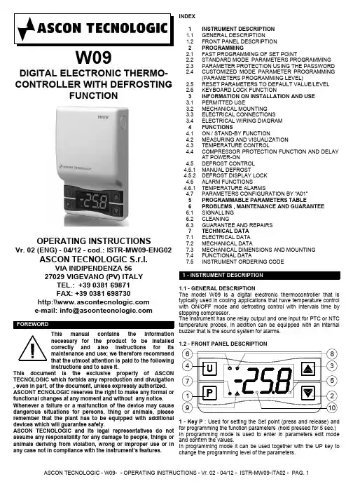
W09DIGITAL ELECTRONIC THERMO-CONTROLLER WITH DEFROSTINGFUNCTIONOPERATING INSTRUCTIONSVr. 02 (ENG) - 04/12 - cod.: ISTR-MW09-ENG02 ASCON TECNOLOGIC S.r.l.VIA INDIPENDENZA 5627029 VIGEVANO (PV) ITALYTEL.: +39 0381 69871FAX: +39 0381 698730http:\\FOREWORDThis manual contains the informationnecessary for the product to be installedcorrectly and also instructions for itsmaintenance and use; we therefore recommendthat the utmost attention is paid to the followinginstructions and to save it.This document is the exclusive property of ASCON TECNOLOGIC which forbids any reproduction and divulgation , even in part, of the document, unless expressly authorized. ASCONT ECNOLOGIC reserves the right to make any formal or functional changes at any moment and without any notice. Whenever a failure or a malfunction of the device may cause dangerous situations for persons, thing or animals, please remember that the plant has to be equipped with additional devices which will guarantee safety.ASCON TECNOLOGIC and its legal representatives do not assume any responsibility for any damage to people, things or animals deriving from violation, wrong or improper use or in any case not in compliance with the instrument’s features.INDEXINSTRUMENT ORDERING CODE7.5FUNCTIONAL DATA7.4MECHANICAL DIMENSIONS AND MOUNTING7.3MECHANICAL DATA7.2ELECTRICAL DATA7.1TECHNICAL DATA7GUARANTEE AND REPAIRS6.3CLEANING6.2SIGNALLING6.1PROBLEMS , MAINTENANCE AND GUARANTEE 6PROGRAMMABLE PARAMETERS TABLE5PARAMETERS CONFIGURATION BY “A01”4.7TEMPERATURE ALARMS4.6.1ALARM FUNCTIONS4.6DEFROST DISPLAY LOCK4.5.2MANUAL DEFROST4.5.1DEFROST CONTROL4.5COMPRESSOR PROTECTION FUNCTION AND DELAYAT POWER-ON4.4TEMPERATURE CONTROL4.3MEASURING AND VISUALIZATION4.2ON / STAND-BY FUNCTION4.1FUNCTIONS4ELECTRICAL WIRING DIAGRAM3.4ELECTRICAL CONNECTIONS3.3MECHANICAL MOUNTING3.2PERMITTED USE3.1INFORMATION ON INSTALLATION AND USE 3KEYBOARD LOCK FUNCTION2.6RESET PARAMETERS TO DEFAULT VALUE/LEVEL2.5CUSTOMIZED MODE PARAMETER PROGRAMMING(PARAMETERS PROGRAMMING LEVEL)2.4PARAMETER PROTECTION USING THE PASSWORD2.3STANDARD MODE PARAMETERS PROGRAMMING2.2FAST PROGRAMMING OF SET POINT2.1PROGRAMMING2FRONT PANEL DESCRIPTION1.2GENERAL DESCRIPTION1.1INSTRUMENT DESCRIPTION11 - INSTRUMENT DESCRIPTION1.1 - GENERAL DESCRIPTIONThe model W09 is a digital electronic thermocontroller that is typically used in cooling applications that have temperature control with ON/OFF mode and defrosting control with intervals time by stopping compressor.The instrument has one relay output and one input for PTC or NTC temperature probes, in addition can be equipped with an internal buzzer that is the sound system for alarms.In programming mode is used to enter in parameters edit mode and confirm the values.In programming mode it can be used together with the UP key to change the programming level of the parameters.2 - Key DOWN values to be set and for selecting the parameters.3 - Key UP/DEFROST manual defrosting (hold pressed for 5 sec.).and for selecting the parameters.parameters level.unlock4 - Key U : variables (measured temperatures etc.) .(hold for 2 sec.).It can also be programmed via the parameter “t.UF”In normal mode and if par. “t.UF” = 4 it can be used to turning on and off (stand-by) the device (hold pressed for 1 sec.)5 - Led SET : In normal mode it serves to indicate when a key is pressed.In programming mode indicates the programming level of the parameters.6 - Led OUT - COOL : Indicates the output status (compressor or temperature control device) when the istrument is programmed for cooling operation; on (on), off (off) or inhibited (flashing).7 - Led OUT - HEAT : Indicates the output status (compressor or temperature control device) when the istrument is programmed for heating operation; on (on), off (off) or inhibited (flashing).When the desired value is set press the key P to exit from Set Point programming mode.Exiting the Set mode is achieved by pressing the P key or automatically if no key is pressed for 10 seconds. After that time the display returns to the normal function mode.2.2 - STANDARD MODE PARAMETERS PROGRAMMINGTo access the instrument’s function parameters when password protection is disable, press the key P and keep it pressed for about 5 seconds, after which the display will visualised the code that identifies the first parameter.Using the UP and DOWN keys, the desired parameter can be selected and pressing the P key, the display will alternately show the parameter code and its setting that can be changed with the UP and DOWN keys.Once the desired value has been set, press the key P again: the new value will be memorised and the display will show only the code of the selected parameter.Pressing the UP and DOWN keys, it is possible to select another parameter and change it as described.To exit the programming mode, do not press any key for about 30seconds, or keep the U key pressed for 2 sec. until it exits the programming mode.2.3 - PARAMETER PROTECTION USING THE PASSWORDThe instrument has a parameter protection function using a password that can be personalised, through the “t.PP” parameter.If one wishes to have this protection, set the password number desired in the parameter “t.PP”.When the protection is activate, press the P key to access the parameters and keep it press for about 5 seconds, after which the display will show “r.P” .At this point press P, the display show “0”, using the UP and DOWN keys, set the password number programmed and press the key P.If the password is correct, the display will visualise the code that identifies the first parameter and it will be possible to program the instrument in the same ways described in the previous section.pressed for 5 seconds.In this way it’s possible to have access to all the parameters, verify and modify the par. “t.PP”.2.4 - CUSTOMIZED MODE PARAMETER PROGRAMMING (PARAMETERS PROGRAMMING LEVEL)The password protection hides all the configuration parameters behind a factory set password to avoid unwanted changes being made to the programming of the controller.To make a parameter accessible without having to enter the password when “t.PP” password protection is activate follows this procedure.Enter the programming using the Password “t.PP” and select the parameter which is desired to be accessible with no password protection.Once the parameter has been selected, if the SET led is blinking,this means that the parameter is programmable by entering the password (it’s then “protected”) if it’s instead on, this means the parameter is programmable without password (not protected).If you want to change the accessibility of the parameter push P key, keep it pressed and press together also the key UP.The led SET will change its state indicating the new access level of the parameter (on = not protected; blinking = protected by password).In case some parameters are not protected, when one tries to have access at the programming, the display will show all theparameters not protected and the par. “r.P” (through which will beprogrammed in factory as default.To restore to the values of default the parameters set the value -48to “r.P” password request.Once confirmed the password with the key P the display it shows "---" for 2 sec. therefore the instrument effects the parameters reset2.6 - KEYBOARD LOCK FUNCTIONOn the instrument it’s possibile to lock completely the keyboard. This function is particularly useful when the regulator is reachable by the users and it’s desired to avoid any modification.To activate the keyboard lock it’s enough program the par. “t.Lo”to a different value to oF.The value program to this parameter it is the time of inactivity of the keys afterwhich the keyboard will be locked.Remember that the end user must periodically checks and verify the thermometers in compliance with standard EN 13486.The installer must ensure that EMC rules are respected, also after the instrument installation, if necessary using proper filters.Whenever a failure or a malfunction of the device may cause dangerous situations for persons, thing or animals, pleaseremember that the plant has to be equipped with additional devicesor plant with permanent connection inside, it is not equipped with either switches or internal devices to protect against overload of current: the installation will include an overload protection and a two-phase circuit-breaker, placed as near as possible to the instrument, and located in a position that can easily be reached by the user and marked as instrument disconnecting device which interrupts the power supply to the equipment. It is also recommended that the supply of all the electrical circuits connected to the instrument must be protect properly, using devices (ex.fuses) proportionate to the circulating currents (see Tech. Data for details). It is strongly recommended that cables with proper insulation, according to the working voltages and temperatures, be used. Furthermore, the input cable of the probe has to be kept separate from line voltage wiring. If the input cable of the probe is The instrument, once powered up, can assume 2 different conditions:- ON : means that the controller uses the control functions.- STAND-BY : means that the controller does not use any control function and the display is turned off except for the led Stand-by.If there is no power, and then power returns, the system always sets itself in the condition it was in before the black-out.The ON/Stand-by function can be selected using the key U if the parameter "t.UF" = 4.Pressing the key U for at least 1 sec., it is possible to switch the instrument from the ON status to Stand-by status and vice versa.4.2 - MEASURING AND VISUALIZATIONVia the parameter “i.SE” it is possible to select the type of probes that one wishes to use and which can be: thermistores PTC KTY81-121 (Pt ) or NTC 103AT-2 (nt ).Via the parameter “i.uP”, it is possible to select the temperature unit of measurement the desired measurement resolution (C0=°C /1° ; C1=°C / 0.1° ; F0= °F / 1°; F1= °F / 0.1°).The instrument allows the measuring to be calibrated, that can beneeds, through the parameters “i.C1”.Using the parameter “i.Ft”, time).U.The display will alternately show:“Lt” and the lowest peak temperature “Ht ” and the highest peak temperature“Pr1” and the instant measured temperaturefor the time “r.t1”, then deactivates it for the time “r.t2” and so on whilst the error remains.Programming “r.t1” = oF the output in probe error condition will remain switched off.Programming instead “r.t1” to any value and “r.t2” = oF the output in probe error condition will remain switched on.Remember that the temperature regulation function can be conditioned by the “Compressor Protections”, “Delay at power on”and “Desfrost” functions.4.4 - COMPRESSOR PROTECTION FUNCTION AND DELAY AT POWER-ONThe function “Compressor Protection” aims to avoid close start ups of the compressor controlled by the instrument in cooling applications.This function foresees 3 time controls on the switching on of the output associated with the temperature regulation request.The protection consists of preventing the output being switched on during the times set in the parameters “P.P1”, “P.P2” and “P.P3”and therefore that any activation occurs only after all the times has finished.4.5 - DEFROST CONTROLThe automatic control of defrost, that is by stopping compressor, occours by interval timesThe automatic defrost function is activate when at the parameter “d.di” is set the defrost interval time.The first defrost after swiching on can be set by par. “d.Sd”This allows to perform the first defrost to a different interval from "d.di." time.If it is desired that to every instrument power on a defrost cycle is realized program the par. "d.Sd" = oF.Instead= "d.di."Automatic defrost function is disable when “d.di” = oF.“d.dE”power on)4.5.1 - MANUAL DEFROSTdefrost and keep it pressed for about 5 seconds.4.5.2 - DEFROST DISPLAY LOCKThrough par. “d.dL” and “A.dA”behaviour during defrost.last temperature reading (“d.dL” =on par. "A.dA".Or it permits only the visualization of label “dEF”during the defrost cycle and, after the defrost, of label par. "A.dA".The display will otherwise (“d.dL”=4.6 - ALARM FUNCTIONSThe alarm conditions of the instrument are:- Probe errors “E1” , “-E1”- temperature alarms “Hi” and “Lo”The alarm functions of the instrument work on the led ALARM and on the internal buzzer, if present and configured via the parameter “o.bu”,The possible selections of the parameter “o.bu” are:= oF - Buzzer always disable= 1 - Buzzer signal active alarms only= 2 - Buzzer signal key pressed only (no alarm)= 3 - Buzzer signal active alarms and key pressedAny active alarm is shown on the instrument display with the lighting up of the ALARM led, the silenced alarm status is shown by the ALARM led flashing .The buzzer (if “o.bu” = 1 or 3) is activated in alarm and can be disabled (alarm silencing) manually by pressing any key of the instrument .4.6.1 - TEMPERATURE ALARMSmeasurement, the type of alarm set in the parameter alarm thresholds set in parameters “A.HA”“” (minimum alarm) and the relative differential absolute (“A.Ay”=1) or relative to the Set Point (“A.Ay”=2).enablement and the intervention of these alarms.These parameters are:“A.PA”switched on.time "A.PA" it is not considered.“A.dA”defrosting“A.At” - is the temperature alarm delay activation timeThe temperature alarm is enabled at the end of exclusion time and is enabled after the “A.At” time when the temperature measured bythe probe exceeds or goes below the respective maximum and minimum alarm thresholds.The alarm thresholds will be the same as those set on the by setting the relative parameters "A.HA" and "" = oF.4.7 - PARAMETERS CONFIGURATION BY “A01”The instrument is equipped with a connector that allows the trans-fer from and toward the instrument of the functioning parameters through the device A01 with 5 poles connector.This device it’s mainly useable for the serial programming of the instruments which need to have the same parameters configuration or to keep a copy of the programming of an instrument and allow its rapid retransmission.The same device A01 allows the USB connection to a PC and through the "TECNOLOGIC UniversalConf" configuration software it is possible to program all the instrument parameters.To access the connector it is necessary to remove power supply,remove the 2 screws on the upper side of the instrument and therefore remove the plastic cover.We recommends to supply A01 and the instrument by the provided power adaptor and DO NOT supply the instrument when the cover has been removed because there are live accessible parts at main voltage.Here below is a description of all the parameters available on the instrument. Some of them may not be present because depend on the model/type of instrument.oF oF/ 0.01 ÷ 9.59(min.sec ) ÷Out delay between switching-on P.P318oFoF/ 0.01 ÷ 9.59(min.sec ) ÷99.5(min.sec.x10)Out delay after switch off P.P217oF oF/ 0.01 ÷ 9.59(min.sec ) ÷ 99.5(min.sec.x10)Out delay at switch on P.P116P. parameters relative to compressor protection and power on delay oFoF - on - Lb Defrost display Lock oF= display freeon = Lock ontemperature Pr1before defrostLb = Lock on label“dEF” (duringdefrosting) and “PdF”(during post-defrosting)d.dL 15oFoF/ 0.01 ÷ 9.59(min.sec ) ÷ 99.5(min.sec.x10)Lenght of defrost cycle d.dE 14oFoF/ 0.01 ÷ 9.59(min.sec ) ÷ 99.5(min.sec.x10)Delay first defrost after power-on (oF = Defrost at power-on)d.Sd 13oFoF/ 0.01 ÷ 9.59(hrs.min. ) ÷99.5(hrs.min.x10)Defrosting interval d.di 12 d. - parameters relative to defrosting controlCH - C Output operating mode H= Heating C= Coolingr.HC 11oFoF/ 0.01 ÷ 9.59(min.sec ) ÷99.5(min.sec.x10)Output deactivation time for probe error r.t210oFoF/ 0.01 ÷ 9.59(min.sec ) ÷99.5(min.sec.x10)Output activation time for probe error r.t19 2.00.0 ÷ 30.0°C/°FDifferential(Hysteresis)r.d 8r. - parameters relative to temperature control0.0-30.0 ÷ 30.0°C/°FProbe Calibration i.C17 2.0oF ÷ 20.0secMeasurement filter i.Ft 6C1C0 / F0 / C1 /F1Unit of measurement and resolution (decimal point)C0 = °C with 1° res.F0 = °F with 1° res.C1 =°C with 0,1° res.F1 = °F with 0,1° res.i.uP 5nt Pt / nt Probes Type i.SE 4 i. -parameters relative to inputs0.0LS ÷ HS Set PointSP 399.9LS ÷ 999Maximum Set Point S.HS 2-50.0-99.9 ÷ HS Minimum Set Point S.LS 1 S. - parameters relative to Set PointNoteDef.Range Description Par.oFoF ÷ 999Access Password to parameter functionst.PP 30oFoF/ 0.01 ÷ 9.59(min.sec ) ÷30.0(min.sec.x10)Keyboard lock function delay t.Lo 29oFoF / 4(1 / 2 / 3 =don’t use)Function mode key U oF= No function 4= Switch on/Switch off (Stand-by)t.UF 28t. - parameters relative to configuration of the keyboard 3oF / 1 / 2 / 3 Buzzer function mode oF = disable1 = active alarms only2 = key pressed only3 = active alarms and key pressedo.bu 27o. -parameters relative to buzzer1.00oF/ 0.01 ÷ 9.59(hrs.min. ) ÷99.5(hrs.min.x10)Temperature Alarms delay and unlock display delay after defrost A.dA 26 2.00oF/ 0.01 ÷ 9.59(hrs.min. ) ÷99.5(hrs.min.x10)Temperature Alarms delay at power on A.PA 25oFoF/ 0.01 ÷ 9.59(min.sec ) ÷99.5(min.sec.x10)Temperature Alarms delay A.At 24 1.00.0 ÷ 30.0°C/°FTemperature Alarms Differential A.Ad 23oFoF / -99.9 ÷999 °C/°FLow temperature Alarm threshold 22oFoF / -99.9 ÷999 °C/°FHigh temperature Alarm threshold A.HA 2111 / 2(/ 3 / 4 / 5 / 6 /7 / 8 = don’t use)Temperature alarms Type:1 = Absolute 2 =Relative to Set A.Ay 20 A. - parameters relative to alarmsoFoF/ 0.01 ÷ 9.59(min.sec ) ÷99.5(min.sec.x10)Delay at power on P.od 1999.5(min.sec.x10)6.1 - SIGNALLINGReplace the instrument or ship to factory forrepairFatal memory error ErrPress key P Internal EEPROM memory error EPr Check the correct connection of the probe with the instrument and check the probe works correctly The probe may be interrupted (E) or in short circuit (-E), or may measure a value outside the range allowed E1-E1Action Reason Error Other Signalling:Minimum temperature alarm in progress LoMaximum temperature alarm in progress HiPost-defrosting in progress with “d.dL”=Lb PdFDefrosting in progress with “d.dL”=Lb dEF Keyboard lock Ln Delay at power-on in progress od ReasonMessageOperating temperature: 0 T 50 °COperating humidity: < 95 RH% without condensation Storage temperature: -25 T 60 °C Display resolution: 1 ° or 0,1° (range -99.9 ...99.9 °)Overall accuracy: +/- (0,5 % fs + 1 digit)Sampling rate: 130 ms.Display: 3 Digit Red (or Blue as option) h 15,5 mmSoftware class and structure : Class ACompliance: Directive 2004/108/CE (EN55022: class B; EN61000-4-2: 8KV air, 4KV cont.; EN61000-4-3: 10V/m; EN61000-4-4: 2KV supply and relay outputs, 1KV inputs; EN61000-4-5: supply 2KV com. mode, 1 KV\ diff. mode; EN61000-4-6: 3V);Directive 2006/95/CE (EN 60730-1, EN 60730-2-9).Regulation 37/2005/CE (EN13485 air, S, A, 2,- 50°C +90°C with probe NTC 103AT11).7.5 - INSTRUMENT ORDERING CODE W09- a b c d e f g h ii jja : POWER SUPPLYH = Supply 100..240 VACb : OUTR = Out Relay SPDT 8A-AC1c : BUZZER- = (No)B = Buzzerd, e, f, g, h : INTERNAL CODESii, jj : SPECIAL CODES。
温度控制器的使用说明书一、产品简介温度控制器是一种用于调节温度的装置。
它通过感知环境温度的变化,并根据设定参数来控制加热或制冷设备的工作状态,以达到温度控制的目的。
本使用说明书旨在帮助用户正确操作和使用温度控制器,提供详细的使用指南和注意事项。
二、产品外观1. 温度控制器的外观设计简洁美观,采用灰色塑料外壳,具有良好的手感和耐用性。
2. 正面面板采用液晶显示屏,可清晰显示当前温度、设定温度以及其他相关信息。
3. 控制按钮位于正面面板下方,用户可通过按钮进行参数设置和操作。
三、使用方法1. 安装a) 在使用温度控制器之前,请先确保断电状态,并按照产品手册提供的安装步骤进行正确安装。
b) 将温度控制器固定在合适的位置,并确保其与被控制的设备连接牢固、接线正确。
2. 参数设置a) 打开温度控制器电源,系统将自动启动并显示当前温度。
b) 按下设置按钮进入参数设置模式,并使用上下按钮选择要设置的参数。
c) 通过加减按钮调节参数数值,确认后按下确认按钮保存设置并退出设置模式。
d) 确保设定的温度范围和控制模式与实际需求相匹配。
3. 运行控制a) 在参数设置完成后,温度控制器将自动开始工作。
在正常工作状态下,控制器将根据设定温度和当前温度进行判断,并控制相关设备的启停。
b) 温度控制器具备过温保护功能,当探测到温度超过设定范围时,控制器将自动切断电源,避免设备过热。
四、注意事项1. 使用前请阅读并确保理解本使用说明书的所有内容,遵循说明书提供的正确操作方法和注意事项。
2. 请勿将温度控制器暴露在恶劣的环境条件下,如强烈阳光直射、高温、潮湿或腐蚀性气体影响的场所等。
3. 温度控制器仅适用于指定的电压和电流范围,请勿使用超过规定的电源供应。
4. 如需更换温度探头,请关闭电源并按照说明书提供的步骤进行更换,以免发生触电或其他意外伤害。
5. 若长时间不使用温度控制器,请将其断电并保存在干燥通风的地方,以延长使用寿命。
温湿度控制器一、产品概述温湿度控制器,主要应用于需要对被测环境进行自动温湿度调节的场合,用户可通过按键分别调整温湿度的上、下限值来控制加热或排风实现自动控制,显示方式为数码管显示。
二、基本功能:2.1 温度测量范围:-25℃~+80℃±1℃;2.2 湿度测量范围:相对湿度RH: 0%~99% 精度±3%RH;2.3 控制方式:温度采用上、下限和回差控制,湿度采用上、下限控制,所有参数均可设置;2.4 输出控制类型:两组继电器触点,分别为加热和排风,每路最大负载AC250V /3A,均为有源输出。
三、技术指标:3.1电源:AC 220V±20%3.2 工作环境:温度:-25℃~+55℃,相对湿度:<95%RH3.3控制设定范围:温度:0℃~80℃,相对湿度:50%RH~99%RH3.4 本机功耗:<3W3.5自检功能:若数码管显示“–––”,则为检测到传感器故障;若加热或排风运行过程中相应指示灯熄灭,则检测到加热或排风故障。
四、工作原理:4.1 温度控制:当被测环境温度低于设定温度下限时,本仪器启动电加热设备开始加温,此时加热指示灯亮,温度升至比下限温度设定值高回差值时,即:W测≥W下限+回差,停止加温。
当被测环境温度高于设定温度上限时,本仪器启动降温设备(如风机或空调)开始降温,此时排风指示灯亮,温度降至比上限温度设定值低回差值时,即:W测≤W上限-回差,停止降温。
4.2 湿度控制:当被测环境湿度超过设定湿度上限时。
如果当前温度较高,即:W测≥W下限+(W上限-W下限)×3÷4,采用降温(或排风,视具体地区采用不同设备)抽湿,此时排风指示灯亮;抽湿过程中,如果温度低于下限温度+2度后,自动转为加热降湿;当降湿过程中温度高于上限温度-2度后,自动转为降温抽湿,直至湿度低于设定下限值为止。
当被测环境湿度超过设定湿度上限时。
如果当前温度较低,即:W测<W下限+(W上限-W下限)×3÷4,采用加热降湿,此时加热指示灯亮,降湿过程中,如果温度高于上限温度-2度后,自动转为降温抽湿;当温度低于下限温度+2度后,自动转为加热降湿,直至湿度低于设定下限值为止。
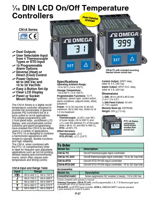
P-27The CN1A Series is a digital on/off temperature controller designed to provide the functionality of general purpose PID controllers but at a price suited to on/off applications. The simple programming with2 front panel keys, uncluttered LCD display, and uncomplicated control functions and alarm programming have enabled the CN1A to be widely used in a variety of applications. The PTC-1A is designed to combine a harmonized appearance withsimple-to-operate, flexible functions and high reliability.The CN1A, when combined with the PTC-1A complimentary timer is ideal for frequent user-adjustable applications such as hot foil printing, window sealing and environmental ovens, which often require both temperature and timing control. U D ual Outputs U U ser Selectable Input from 4 Thermocouple Types or RTD Input U 10 Programmable Alarm Options U R everse (Heat) or Direct (Cool) Control U Power Options: 90 to 260 Vac and 10 to 32 Vac/Vdc U E asy 2-Button Set-Up U C lear LCD Display U Panel or Socket Mount DesignSpecificationsOperating Ambient Range: -10 to 50°C (14 to 122°F)Storage Temperature: -20 to 85°C (-4 to 185°F)Programmable Functions: °C/°F, hysteresis, sensor type, control action, alarm conditions, setpoint limits, offset, Control Output: SPDT relay, rated @ 3 A, 240 VacAlarm Output: SPST N.O. relay, rated @ 3 A, 240 VacDimensions1⁄16 DIN: 48 H x 48 W x 89 D mm (1.9 x 1.9 x 3.5")1⁄16 DIN Panel Cutout: 45 mm CN1A-TC with included mounting bracket shown actual size.1⁄16 DIN LCD On/Off Temperature ControllersComes complete with operator’s manual.Ordering Examples: CN1A-TC-24V, on/off programmable J, K, T, N thermocouple input controller with 10 to 32 Vac/dc power.CN1A-RTD, on/off RTD input controller. OCW-3, OMEGACARE SM extends standard 1-year warranty to a total of 4 years.P a n e l P u nc h esA v a i l a b l e。
温度控制器的说明书一、产品介绍温度控制器是一种用于控制温度变化的设备,通常应用于各类加热或冷却系统中,以确保温度的稳定和准确性。
本说明书将详细介绍温度控制器的使用方法、技术规格以及安全注意事项。
二、技术规格1. 输入电压:AC 220V2. 控制类型:PID控制3. 温度范围:-50℃至+150℃4. 温度精度:±1℃5. 输出类型:继电器输出6. 外观尺寸:120mm×80mm×40mm三、使用方法1. 连接电源:将温度控制器的电源线连接到AC 220V电源上。
2. 连接传感器:根据需要,将温度传感器连接到温度控制器的探头接口上。
3. 设置温度目标值:使用温度控制器面板上的按钮和显示屏,设置所需的温度目标值。
4. 参数调整:按照需要,调整PID控制参数以实现更准确的温度控制。
5. 启动控制器:按下温度控制器面板上的启停按钮,控制器将开始工作并调节系统温度。
6. 监控温度:使用控制器面板上的显示屏,实时监控当前温度以及目标温度。
四、安全注意事项1. 在安装和操作控制器之前,请确保断开电源以防止电击事故。
2. 请根据产品规格正确选择电源电压,使用不符合规定电压的电源会导致设备损坏。
3. 定期检查控制器、传感器和电缆的连接是否牢固,避免松动或脱落导致设备故障。
4. 请勿在潮湿、腐蚀性或易燃易爆环境中使用温度控制器,以免引发安全事故。
5. 在长时间不使用时,建议将温度控制器断开电源,并储存在干燥、通风良好的地方。
6. 如果发现异常情况或设备故障,请立即断电并寻求专业人员进行维修。
以上是温度控制器的说明书,希望能帮助您正确、安全地使用该设备。
如有任何疑问或问题,请咨询售后服务部门,感谢您的支持与配合。
注:本说明书仅供参考,请以实际产品附带的说明书为准。
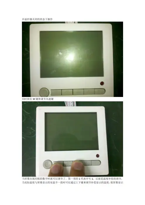
在温控器关闭的状态下操作
同时按住M键和调节风速键
当屏幕出现闪烁的数字时就可以调节了。
第一项的1代表序号1,后面是温度补偿的调节,当实际温度与屏幕显示的室温不一致时可以通过上下键来调节补偿显示的温度,使屏幕显示
的实际温度与环境的温度一致。
按M键可以进入第二项,第二项代表的意思是冷风的下限,就是当空调吹冷风时,温度调节最低可以调到10度,再往下调就没反应了,(备注:调节时候应快速调节,如无动作三秒后屏幕自动关闭,只能回到第一步重新操作。
)
按M键进入第三项,第三项为暖风的上限,意思正好和第二项相反,当空调吹暖风的时候,温度最高可以调到30度,再往上按就没有变化了。
如温控器的冷风下限和暖风上限不是这两个温度,请按照此步骤调至此温度。
上下限必须为此两项值
按M键进入下一项,此项为温控器地址码的调节,(既:右下角显示的10 33.)此项为调节地址前项码,当客房只有一个温控器时,地址必须为10 33.当客房有两个温控器时第一个温控器的地址码为10 33,第二温控器的地址为10 34. 数量再增加以此类推。
按M键进入下一项,此项为地址码的尾项调节。
(既右下角显示的10 33. 33这一数字的调节。
)
当屏幕出现下图的字样,且能开机时,
表示温控器面板已经锁住,可以同时按住温度调节的上下键3秒,便可以解锁。
另附:当调节的温度大于室温时,必须将吹风调至暖风。
当调节的温度小于室温时,必须将吹风调至冷风。
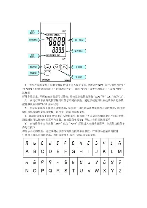
(1)首先在运行菜单下同时按和3 秒以上进入保护菜单,然后将“OAPT(运行/调整保护)”和“ICPT(初始/通信保护)”的值改为“0”,再将“WTPT(设置更改保护)”改为“OFF”,这样就
解除参数锁定,即所有的参数都可以修改。
要恢复参数锁定请将“OAPT”和“ICPT”改为“2”。
(2)在运行菜单内每次按下键可以显示不同的参数,通过按或键可以修改菜单内的参数。
按键多次后回到PV/SV 显示状态
(3)在运行菜单按下键进入调整菜单,每次按下可以显示调整菜单内不同的参数,通过或键可以修改调整菜单内参数。
再次按下将返回运行菜单
(4)在运行菜单按下键3 秒以上进入初始菜单,每次按下可以显示初始菜单内不同的参数,通过或键可以修改初始菜单内参数。
在初始菜单按键1 秒以上将返回运行菜单
(5)在初始菜单内将参数“AMOV”改为“-169”后将进入高级功能菜单,在高级功能菜单内每次按下
将显示不同的参数,通过或键可以修改高级功能菜单内参数。
在高级功能菜单内按键
1 秒以上将返回初始菜单,然后再按键1 秒以上将返回运行菜单。
欧姆龙温度控制器中文手册1、产品介绍1.1 产品概述欧姆龙温度控制器是一种用于温度调节和监测的设备,能够实时监测目标对象的温度并通过控制输出来调节温度。
1.2 产品特点- 高精度温度监测:欧姆龙温度控制器可以提供高精度的温度监测,确保目标对象的温度得到准确测量。
- 稳定的温度控制:通过控制输出,欧姆龙温度控制器能够实现对目标对象的温度进行稳定控制,确保温度在设定范围内保持稳定。
- 多种控制模式:欧姆龙温度控制器支持多种不同的控制模式,包括PID控制、ON/OFF控制等,以满足不同的应用需求。
- 友好的用户界面:欧姆龙温度控制器具有直观的用户界面,易于操作和设置。
1.3 适用范围欧姆龙温度控制器适用于需要对温度进行调节和监测的各种应用场景,包括工业生产、实验室研究等。
2、产品安装与设置2.1 安装要求在安装欧姆龙温度控制器时,需满足以下要求:- 安装位置应远离高温、湿度、振动和腐蚀性气体等因素。
- 与电源线和信号线的布线应符合相关安全规范。
- 温度探头应与目标对象接触良好,以确保温度测量的准确性。
2.2 设置步骤以下是设置欧姆龙温度控制器的步骤:1.连接电源线和信号线:将电源线和温度探头的信号线分别连接到欧姆龙温度控制器的相应接口上。
2.打开电源:将电源线插入电源插座,并打开电源开关。
3.进入设置模式:按下欧姆龙温度控制器的设置按钮,进入设置模式。
4.设置参数:根据实际需求,设置目标温度、控制模式、控制范围等参数。
5.保存设置:设置完成后,按下保存按钮,保存设置参数。
6.开始控制:按下启动按钮,欧姆龙温度控制器开始工作。
3、产品使用说明3.1 温度调节欧姆龙温度控制器通过调节控制输出来实现对目标对象温度的调节。
根据不同的控制模式,控制输出可以采用不同的方式,比如调节加热器功率或开关状态。
3.2 温度监测欧姆龙温度控制器可以实时监测目标对象的温度,并将温度值显示在用户界面上。
用户可以通过监测结果了解目标对象的温度变化情况。
意大利ASCON温控器、ASCON温控表、ASCON温度变送器
上海富万国际贸易有限公司代理销售意大利ASCON温控器、ASCON温控表、ASCON温
度变送器、ASCON可编程控制器、ASCON电磁阀、ASCON真空阀控制器、ASCON继电器等产品,价格优惠。
意大利Ascon公司自1969 年就开始控制仪器和程序控制系
统的设计、生产和营销工作。
ASCON 使命是追求产品不断改善和用户满意至上,
ASCON产品全部通过CE 、UL认证。
ASCON产品的型号有:C1系列、M1系列、M3系列
、M5系列等产品。
意大利Ascon公司自1969 年就开始控制仪器和程序控制系统的
设计、生产和营销工作。
ASCON 使命是追求产品不断改善和用户满意至上,ASCON
产品全部通过CE 、UL认证。
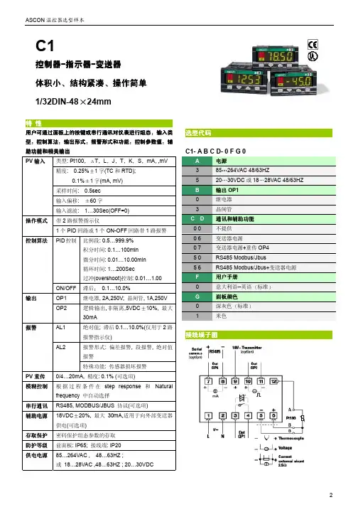
ASCON 温控器选型样本2用户可通过面板上的按键或串行通讯对仪表进行组态输入类型控制算法输出形式报警形式和功能控制参数值辅助功能和相关输出类型: Pt100T LJT K S mA, ,mV精度: 0.25%1字(TC 和RTD); 0.1%1字(mA, mV)采样时间: 0.5sec 输入偏移:60字PV 输入输入滤波: 1…30Sec(OFF=0)带2路报警指示仪操作模式1个PID 回路或1个ON-OFF 回路带1路报警PID 控制 比例段: 0.5…999.9%积分时间: 0.1…100min 微分时间: 0.01…10.00min 循环时间: 1…200Sec过冲(overshoot)控制: 0.01…1.00控制算法ON/OFF 滞后0.1…10.0%OP1 继电器, 2A,250V; 晶闸管, 1A,250V 输出OP2逻辑输出,非隔离,5VDC 10%, 最大30mAAL1 绝对值; 滞后0.1…10.0%(仅用于2路报警指示仪)报警形式: 偏差报警, 段报警, 绝对值报警报警 AL2 特殊功能: 传感器损坏报警PV 重传 0/4…20mA, 精度: 0.1% (可选项)模糊控制根据过程条件在step response 和 Natural frequency 中自动选择串行通讯 RS485, MODBUS/JBUS 协议(可选项) 辅助电源18VDC20%, 最大30mA,适用于向外部变送器供电(可选项)存取保护 密码保护组态参数的存取 防护等级 前面板: IP65; 接线端: IP20 供电电源85…264VAC , 48…63HZ ;或 18…28VAC ,48…63HZ ; 20…30VDCC1- A B C D- 0 F G 0电源 3 85264VAC 48/63HZ 5 2030VDC 或1828VAC 48/63HZ输出OP1 0 继电器 3 晶闸管通讯和辅助功能 0 0 不提供 0 6 变送器电源0 7 变送器电源+重传OP4 5 0 RS485 Modbus/Jbus5 6 RS485 Modbus/Jbus+变送器电源 用户手册0 意大利语--英语标准面板颜色 0 深灰色标准1米色C1控制控制器器-指示器-变送器 体积小结构紧凑操作简单1/32DIN-4824mm。
ASCON spavia Falzarego 9/11 20021 博拉特意大利(米兰)电话: +39 02 333 371传真: +39 02 350 4243网址:温度控制器1/16德国标准 -48x48系列M1线用户手册•编号J30-478-1AM1 IE通过ISO9001认证温度控制器1/16德国标准 -48x48M1线对电气安全和电磁兼容的注释在安装控制器前,请先认真阅读下列指导。
第二类仪器,后面板安装。
控制器按照以下内容设计:电气设备规则根据欧洲共同体第93/68/EEC号指令修正的欧洲共同体第73/23/EEC号指令(设备、系统和安装)以及电气设备EN61010-1 :93 + A2:95中关于强制保护要求的规则。
电磁兼容规则根据欧洲共同体第n° 92/31/EEC、93/68/EEC和98/13/EEC号指令修正的欧洲共同体第n089/336/EEC号指令,并遵守以下规则:射频排放规则:EN61000-6-3 : 2001 居住环境EN61000-6-4 : 2001 工业环境射频抗扰度规则:EN61000-6-2 : 2001 工业设备和系统让安装者了解其应遵守安全要求和EMC规则至关重要。
该设备不具备可供用户使用的部件,且需要使用专用设备并通过专业工程师来操作。
因此,用户不能轻易直接对设备进行维修。
为此,生产商可为客户提供技术援助和维修服务。
欲知详情,敬请联系最近的代理商。
所有关于安全和电磁兼容信息和警告都在注释侧面标明了标志。
目录安装 (4)2电气连接 (8)3产品编码 (14)4操作 (18)5自动调准 (28)6技术规范 (29)指示专主要通用输入单一资源工作模式单一控制警告重新传设置点特殊功能通过自动选择模糊调单次对单次对焦RS485通讯接口1 安装只有合格人员才能进行安装在安装控制器前,请遵守该手册中的指令,特别是标有标志的安装防范,该标志与欧洲共同体关于电气保护和电磁兼容的指令有关。
1.手动/自动无扰动切换按A/M键,MAN指示灯亮,进入手动状态。
当前SV显示器数值即为输出百分比,PV 显示器为测量值。
用“向左”、“向上”和“向下”键可手动修改输出百分比。
再按A/M 键,MAN指示灯熄灭,仪表进入自动状态。
此时,SV显示原设定值,PV显示仍为测量值。
仪表在任何状态下均可进入手动/自动状态。
2.人工修改PID参数在LEVEL1下,按SET键5s进入LEVEL2,按SET键选择P、I和D参数选项即可进行设定。
3.室温显示修正热电偶分度号输入时,若输入端子短接,仪表显示值应近似为室温,若有较大差异,同时按下SET键和“向左”键,进入LEVEL3,然后按SET键数次,找到PVS选项,人工设定修正PVS值。
4.恒温定时报警设定需设定恒温报警时,先选择报警组别(AL1和AL2均可),并设定报警模式为9,然后对该组AL输入定时数值(单位为min)。
当PV=PS时,该组别报警灯亮(继电器无动作),并立刻开始计时(预设定时数值递减为0000),定时结束,报警继电器动作。
5.软启动预置斜率控制(选配)当系统需要软启动时(SV预置斜率升温),按如下顺序操作:设定好SV值→在LEVEL1下按SET键找到RAP选项,设定好温度→按SET键找到RTM选项,设定斜率时间(单位为min)。
例如要设斜率为10℃/min时,RAP设为10.0,RTM设为001.0即可。
设定完毕,软启动将会立即从当前的PV值按斜率升温,直到PV=SV为止。
若需暂停斜率升温,同时按下SET键和“向上”,SV数值可任意修改,进行定值控制。
若要取消软启动,输入0.0℃/min即可。
6.除湿功能(选配)需除湿时按如下顺序操作:在LEVEL3下,按SET键数次找到SRT选项,预置除湿工作时的输出百分比,可预置V=2.0-5.0(例如,SRT设为40℃,LMO设为2.0,即仪表开机时系统的温度低于40℃时,仪表以2%的功率输出,这样可避免烧坏加热器)。
Siebe Group CompanyPatented PDSIO® Load DiagnosticsPDSIO® (Pulse Density SignalingInput/Output) is a patented innovation in the 2208e. When used in combination with the Eurotherm TE10S Solid State Contactor, the same wires from the 2208e that transmit the logic output to the SSC can be used to read back load faults, SSC status and load RMS on-current. SSC failure (open or short circuit) or load failure (fuse blown, heater open circuit,missing line voltage) alarms can bedetected, flash on the front panel andtrip alarm relays. Amperage informationcan be read, displayed, and alarmed.PDSIO® information is also available onserial communications. PDSIO® is notavailable on the Valve Positioner.AlarmsUp to four process alarms may be combinedto a single alarm output. Alarms may befull scale high or low, deviation, rate ofchange or PDSIO® load failure. Alarmsmay be latching or non-latching and willflash on the front panel. Blocking alarms,which only become enabled after firstentering a safe state, are also available.Digital CommunicationsEIA-485 2-wire, EIA-422 4-wire or EIA-232serial communications is optionally availablewith industry standard Modbus® orproprietary EI-Bisynch protocol.Load diagnostic using Pulse Density Signaling Input/Output (PDSIO®)2208e TECHNICAL SPECIFICATIONInputsGeneral Range±100mV and 0 to 10Vdc (auto ranging)Sample rate9Hz (110mS)Calibration accuracy0.25% of reading, ±1 LSD or ±1°C/FResolution<1µV for ±100mV range, <0.2mV for 10Vdc rangeLinearizaton accuracy<0.1% of readingInput filter 1.0 to 999.9secsZero offset User adjustable over the fully display rangeThermocouple Types Refer to Sensor inputs and display ranges tableCold junction compensation Automatic compensation typically >30 to 1 rejection of ambient temperature changeExternal references 32, 113 and 122°F (0, 45 and 50°C).Incorporates INSTANT ACCURACY™ cold junction sensing technology.RTD/PT100Type3-wire, Pt100 DIN43760Bulb current0.2mALead compensation No error for 22 ohms in all 3 leadsProcess Linear±100mV, 0 to 20mA or 0 to 10Vdc (configurable between limits)Digital Type Contact closureApplication Manual select, 2nd setpoint, keylock and setpoint rate limit enableMode 5 Smart Digital Input™ (SDI), only on Digital LA inputOutputsRelay Rating: 2-pin relay Min: 12V, 100mA dc Max: 2A, 264Vac resistiveRating: change-over, alarm relays Min: 6V, 1mA dc Max: 2A, 264Vac resistiveApplication Heating, cooling or alarmsLogic Rating18Vdc at 24mA (non-isolated)Application Heating, cooling or alarmsThe logic output is field configurable as a standard logic output, PDSIO® Mode 1 or PDSIO®Mode 2.PDSIO® Mode 1:Logic heating with load failure alarm (also called SSRx Load Doctor™)PDSIO® Mode 2: Logic heating with load/SSC failure alarm and load current display (also calledSSRx Enhanced Load Doctor™)Triac Rating1A, 30 to 264Vac resistiveApplication Heating or coolingAnalog Range Isolated 0 to 20mA (into 600Ωmax) or 0 to 10Vdc (configurable between limits)Application Heating or coolingCommunicationsDigital Transmission standard EIA-485 2-wire, EIA-422 4 wire or EIA-232 at 1200, 2400, 4800, 9600, 19,200 baud Protocols Modbus® or EI-BisynchPDSIO®Setpoint input Setpoint input from master PDSIO® controller, also called Smart Setpoint Transmission™ (SST) Control functionsControl Modes PID or PI with overshoot inhibition, PD, P only or On/OffApplication Heating and coolingAuto/manual Bumpless transferSetpoint rate limit0.01 to 99.99 degrees or display units per minuteCooling algorithms Linear; Water (non-linear); Fan (minimum on time), Oil, proportional onlyTuning One-shot tune Automatic calculation of PID and overshoot inhibition parametersAutomatic droop compensation Automatic calculation of manual reset value when using PD controlAlarms Types Full scale high or low. Deviation high, low, band or any new alarm.Modes Latching or non-latching. Normal or blocking actionUp to four process alarms can be combined onto a single outputGeneralDisplay Dual, 4 digit x 7 segment high intensity LEDDimensions and weight 1.89W x 3.78H x 4.06D in (48W x 96H x 103Dmm) 14.1oz (400g)Supply85 to 264Vac -15%, +10%. 48 to 62Hz. 10watts maxTemperature and RH Operating: 32 to 131°F (0 to 55°C), RH: 5 to 90% non-condensing. Storage: 14 to 158°F (-10 to 70°C)Panel sealing IP 65Electromagnetic compatibility Meets generic emissions standard EN50081-2 for industrial environmentsMeets general immunity requirements of EN50082-2(95) for industrial environmentsSafety standards EN61010, installation category 2 (voltage transients must not exceed 2.5kV)Atmospheres Electrically conductive pollution must be excluded from the cabinet in which this controller ismounted. This product is not suitable for use above 6,562ft (2000m) or in corrosive or explosiveatmospheres without further protection.3.78i n (96m m )OP1OP2SP2REMPanel cut-out3.62in x 1.77in (92mm x 45mm)-0.0+0.8。
ASCON spa via Falzarego 9/11 20021 博拉特 意大利(米兰) 电话: +39 02 333 371 传真: +39 02 350 4243 网址:温度控制器1/16德国标准 -48x48系列M1线用户手册•编号J30-478-1AM1 IE通过ISO9001认证温度控制器1/16德国标准-48x48M1线对电气安全和电磁兼容的注释在安装控制器前,请先认真阅读下列指导。
第二类仪器,后面板安装。
控制器按照以下内容设计:电气设备规则根据欧洲共同体第93/68/EEC号指令修正的欧洲共同体第73/23/EEC号指令(设备、系统和安装)以及电气设备EN61010-1 :93 + A2:95中关于强制保护要求的规则。
电磁兼容规则根据欧洲共同体第n°92/31/EEC、93/68/EEC和98/13/EEC号指令修正的欧洲共同体第n089/336/EEC号指令,并遵守以下规则:射频排放规则:EN61000-6-3 : 2001 居住环境EN61000-6-4 : 2001 工业环境射频抗扰度规则:EN61000-6-2 : 2001 工业设备和系统让安装者了解其应遵守安全要求和EMC规则至关重要。
该设备不具备可供用户使用的部件,且需要使用专用设备并通过专业工程师来操作。
因此,用户不能轻易直接对设备进行维修。
为此,生产商可为客户提供技术援助和维修服务。
欲知详情,敬请联系最近的代理商。
所有关于安全和电磁兼容信息和警告都在注释侧面标明了标志。
目录安装 ..................................................................................................................... 第4页 电气连接 ............................................................................................................. 第8页 3 产品编码 ............................................................................................................. 第14页 4 操作 ..................................................................................................................... 第18页 5 自动调准 ............................................................................................................. 第28页 6 技术规范 . (29)(可选)指示专用主要通用输入单一动作资源 工作模式 单一动作 控制警告重新传输设置点 特殊功能通过自动选择模糊调整单次对焦自动调整单次对焦固有频率RS485通讯接口参数化监督1 安装只有合格人员才能进行安装在安装控制器前,请遵守该手册中的指令,特别是标有标志的安装防范,该标志与欧洲共同体关于电气保护和电磁兼容的指令有关。
温度控制器使用说明书一、产品概述温度控制器是一种用于控制和调节温度的设备。
它可以实时监测环境温度,并按照预设的温度范围进行自动控制,以确保温度保持在设定值内。
二、产品组成1.主机:包含显示屏、按键和控制电路等组件,用于设置和监控温度控制器的工作状态。
2.传感器:用于感知环境温度的变化,并将其转化为电信号,传输给主机进行处理。
3.输出端口:用于连接外部设备,如加热器、冷却器等,以实现温度调节。
三、使用步骤1.连接电源:将温度控制器插入电源插座,并确保电源稳定。
2.连接传感器:将传感器插入温度控制器的传感器接口中,并确保连接牢固。
3.设置温度范围:按照产品说明书中的指引,通过按键设置所需的温度范围。
4.连接外部设备:根据需要,使用合适的电缆将外部设备连接至温度控制器的输出端口上。
5.开机:按下电源按钮,温度控制器将开始运行,并在显示屏上显示当前温度及工作状态。
6.调试和调节:根据实际需要,适时调整温度控制器的参数,以达到预期的温度控制效果。
四、注意事项1.请确保温度控制器在通风良好的环境中工作,避免遮挡或靠近高温的物体。
2.避免温度控制器长时间暴露在潮湿、尘土等有害环境中,以免影响正常使用寿命。
3.使用前请认真阅读产品说明书,并按照要求正确操作,以免因误操作导致设备损坏或操作失误。
4.在设置温度范围时,请合理选择上下限,避免因温度波动过大造成设备故障或无法达到所需温度。
5.如遇到温度控制器异常工作或其他问题,请及时联系售后服务中心进行咨询或维修。
五、常见问题解答1.温度控制器显示屏无法正常工作怎么办?答:请检查电源接口是否接触良好,确认电源供电充足,并检查是否有异常开关或损坏的部件。
2.温度控制器无法控制温度在设定范围内怎么办?答:请确认传感器连接是否正确,温度控制器和外部设备的连接是否稳固,并适时调整温度范围和控制参数。
3.温度控制器显示温度与实际温度不一致怎么办?答:请检查传感器的位置是否合理,避免受到外部干扰,如阳光直射或其他热源等。
ASCON spa via Falzarego 9/11 20021 博拉特 意大利(米兰) 电话: +39 02 333 371 传真: +39 02 350 4243 网址:http://www.ascon.it 邮箱:support@ascon.it温度控制器1/16德国标准 -48x48系列M1线用户手册•M.I.U.M1-4/04.07•编号J30-478-1AM1 IE通过ISO9001认证温度控制器1/16德国标准-48x48M1线对电气安全和电磁兼容的注释在安装控制器前,请先认真阅读下列指导。
第二类仪器,后面板安装。
控制器按照以下内容设计:电气设备规则根据欧洲共同体第93/68/EEC号指令修正的欧洲共同体第73/23/EEC号指令(设备、系统和安装)以及电气设备EN61010-1 :93 + A2:95中关于强制保护要求的规则。
电磁兼容规则根据欧洲共同体第n°92/31/EEC、93/68/EEC和98/13/EEC号指令修正的欧洲共同体第n089/336/EEC号指令,并遵守以下规则:射频排放规则:EN61000-6-3 : 2001 居住环境EN61000-6-4 : 2001 工业环境射频抗扰度规则:EN61000-6-2 : 2001 工业设备和系统让安装者了解其应遵守安全要求和EMC规则至关重要。
该设备不具备可供用户使用的部件,且需要使用专用设备并通过专业工程师来操作。
因此,用户不能轻易直接对设备进行维修。
为此,生产商可为客户提供技术援助和维修服务。
欲知详情,敬请联系最近的代理商。
所有关于安全和电磁兼容信息和警告都在注释侧面标明了标志。
目录1 安装 ..................................................................................................................... 第4页 2 电气连接 ............................................................................................................. 第8页 3 产品编码 ............................................................................................................. 第14页 4 操作 ..................................................................................................................... 第18页 5 自动调准 ............................................................................................................. 第28页 6 技术规范 . (29)(可选)指示专用主要通用输入单一动作资源 工作模式 单一动作 控制警告重新传输设置点 特殊功能通过自动选择模糊调整单次对焦自动调整单次对焦固有频率RS485通讯接口参数化监督1 安装只有合格人员才能进行安装在安装控制器前,请遵守该手册中的指令,特别是标有标志的安装防范,该标志与欧洲共同体关于电气保护和电磁兼容的指令有关。
为防止手或金属接触零件而通电,必须将控制器安装在外壳和/或箱内。
1.1 概述面板表面产品条码标签安装夹具密封前面板垫前面板 IP65保护EN650529(IEC529)IP20 接线盒EN61010-1(IEC1010-1)1.2 尺寸详图 1.3 面板尺寸图20mm 最长0.79in 最长65mm最短2.56in 最短65mm最短2.56in最短1.4 环境评定等级操作条件海拔可达2000m温度0-50℃%Rh 相对湿度5%-95%不凝结特殊条件建议使用24V交流电供电版本高度>2000m使用强制空气通风温度>50℃%Rh 湿度>95% 加热使用过滤器导电空气禁止条件腐蚀性空气爆燃性空气1.5 面板安装 [1]1.5.1 插入仪器1 将面板切口准备好2 检查前面板垫的位置 3将仪器插入切口UL 注释[1]供在2类和3类“防雨”外壳平整表面上使用。
1.5.2 安装固定1 放置安装夹具2将安装夹具推至面板表面以固定仪器1.5.3 拆除夹具1 将螺丝刀插入夹具夹片中 2旋转螺丝刀1.5.4取下仪器1 向前推,然后 2向后拉,以拆卸仪器静电放电可能对仪器造成损坏,在拆卸仪器前,操作员必须将接触地面将身上的静电放掉。
2 - 电气连接2 电气连接UL 注释[1] 仅使用60/70℃铜(Cu )导线。
2.1 终端单元 [1]14螺旋式接线柱 任选接线柱拧紧力矩0. Nm正极螺丝刀PH1 负极螺丝刀0.8×4 mm接线端插头连接器 1.4 mm 0.055 in (最长处) 叉形 AMP165004 5.5mm-0.21 in条形导线 L 5.5 mm-0.21 in后端子盖导线规格 1mm 2 (18AWG 固体/绞成股状)2 - 电气连接警告尽管已将仪器设计为可在恶劣和吵闹的环境(IEC801-4工业标准IV级)中工作,但还是强烈建议遵守以下建议。
所有接线应遵守本地规则。
规定供电线在铺设时应与电源线分开。
不要使用邻近的电磁导体、电源继电器和大功率电机。
不要使用邻近的供电装置,特别是通过相位角控制的供电装置。
使低位传感器输入导线远离电源线和输出线。
如果无法做到,则可在传感器输入线上使用屏蔽线,并将屏蔽线与地面相连。
2.2 警告和建议的导线铺设路程电源线和输出线用导管低位传感器电线用导管A=电源B=输出C=模拟输入D=模拟输出系列通信E=SSR驱动输出2.3 接线图示例注释:1] 确保电源电压与仪器上显示的数据一致。
2] 只有在完成所有电器连接后才能打开电源。
3] 根据安全规则,电源开关应能识别相关仪器。
操作员应能容易接触到电源开关。
4] 用PTC 将仪器保护好。
如果损坏,建议将仪器送回至生产商处维修。
5] 使用以下内容保护仪器内部电路:-2 AT/250Vac (4AT/120Vac )继电器输出用保险丝 -1 A~ T 可控硅触发输出用保险丝 6] 继电器触电都已使用变阻器保护。
仅在万一出现24Vac 电感性负载时使用A51-065-30D7式变阻器(根据要求)。
电源监控重新传输电源开关2.5Ω外部分流电阻保险丝2线制变送器保险丝2.3.1电源使用多路绝缘和内部PTC 转换电源 ● 标准版:标称电压:100-240Vac (-15~+10%)频率 50/60Hz● 低压版:标称电压:24Vac (-25~+12%)频率 50/60Hz 或 24Vdc (-15~+25%) ●最大功率消耗 2.6W2.3.2OP1输出A]单继电器输出 ● 未接触最大值为2A/250Vac (4A/120Vac )的电阻负载● 保险丝2AT/250Vac (4AT/120Vac )(IEC 127)B]可控硅触发输出 ● 未接触最大值为1A/250Vac 的电阻负载 ● 保险丝1A~T (IEC 127)2.3.3 OP2输出A]SSR 驱动输出,未绝缘 0-5Vdc 、±20%、最大值30MaB]单相继电器输出 ● 未接触最大值为2A/250Vac (4A/120Vac )的电阻负载● 保险丝2A~T (IEC 127)包括PTC 电源保险丝保险丝负载导体线圈 电感负载用变阻器 仅限24Vac 负载静态继电器 负载导体线圈电感负载用变阻器 仅限24Vac负载导体线圈电感负载用变阻器 仅限24Vac保险丝OP2 输出OP2输出类型可以为继电器(标准)或SSR 驱动。
辅助配电盘上的“跨接线”可以选择以下的输出类型:OP2-继电器用连杆梢1-2OP2-SSR驱动用连杆梢1-22.3.4 OP4输出(可选)PV重新传输●绝缘,最小值500Vac/1●0/4-20mA(750Q 或最大值15Vdc)2.3.5 串行通信(可选)●绝缘,最小值500Vac/1●遵守Modbus/Jbus通信协议的EIA RS485标准请阅读:gammadue®和deltadue®控制器系列串行通信和配置跨接线辅助配电盘负载2.3.6 PV控制输入●将导线与如图所示的两级连接●仅使用正确型号的热电偶补偿电线●如有防护罩,必须连接合适的地面LJKST型热电偶mA、mV 和V●如果使用3线系统,则只能使用同样尺寸(最小1 mm2)的电线。
(线路20Ω/最大引线电阻)●如果使用2线系统,则只能使用同样尺寸(最小1.5mm2)的电线,并应在接线柱5和6之间放置一个跨接线控制器与传感器相距15m时,如使用规格为1.5mm2的电线,会导致1℃的测量偏差。
PT100电阻温度计ΔT(2 x RTD Pt100)特殊R1+R2必须<320Ω配有2线变送器仅供3线使用最大线阻力:20Ω/线使用相同长度以及1.5mm2大小的电线最大线阻力:20Ω/线外部分流器2.5Ω变送器变送器外部分流器2.5Ω金属膜电阻>10MΩ导线阻力最大值150Ω3产品编码仪器的标签上标有完整的编码。
产品编码方面的信息可根据第4.2.2节(第19页)中描述的特殊程序的方法从前面板中获得。
仪器标签品名:M1-3000-0000配置:2002序号:A0A-9809/0013V~(L-N): 85+264V 50/60 Hz -2.6W基本产品编码(硬件)配置编码(软件)3.1 类型编码产品编码表明仪器的特殊硬件配置,仅能由专业工程师修改。
线基本附件配置型号:如果首次启动控制器,显示屏上将显示以下信息。
这表明控制器还未配置好。
该控制器一直处于备用状态,直到正确设置配置编码(参见第26页的第4.6章)。
注释[1] 控制器配置2个报警指示器时,选择无法使用(指定4或5个L 数位)。
4 操作4.1 键盘命令和显示PV 控制输入(操作者模式)(设计单位中)测量值大于传感器的最大刻度时测量值小于传感器的最低刻度时编码和/或参数值(编程模式)偏差指示器(SP-PV )绿色发光二极管亮 OK绿色发光二极管亮+1个红色发光二极管亮只有红色发光二极管亮OP1 输出亮(红) OP2输出亮(红) 正调整(绿)选择和设定值确认的回车键数值修改快捷菜单4.2 显示选择显示操作时,控制器可以自动显示所有最重要的参数和配置信息。