C5191磷青铜机械性能参数
- 格式:docx
- 大小:9.54 KB
- 文档页数:2
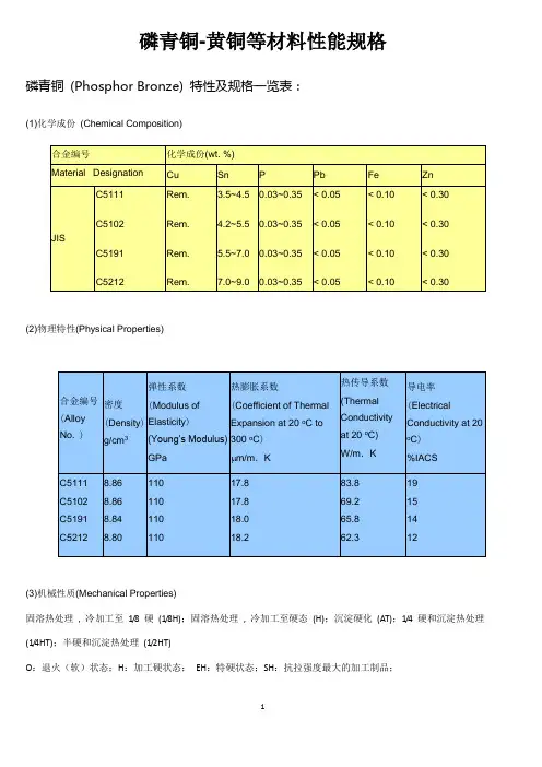
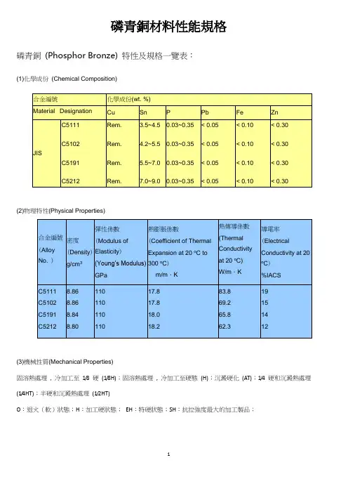
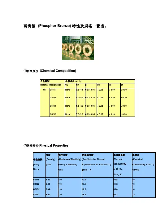
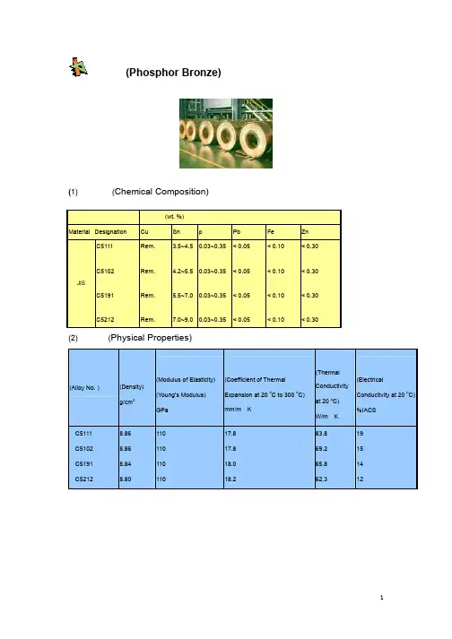
磷青铜-黄铜等材料性能规格磷青铜(Phosphor Bronze) 特性及规格一览表:(1)化学成份(Chemical Composition)(2)物理特性(Physical Properties)(3)机械性质(Mechanical Properties)固溶热处理, 冷加工至1/8 硬(1/8H);固溶热处理, 冷加工至硬态(H);沉淀硬化(AT);1/4 硬和沉淀热处理(1/4HT);半硬和沉淀热处理(1/2HT)O:退火(软)状态;H:加工硬状态;EH:特硬状态;SH:抗拉强度最大的加工制品;Mechanical Properties (continuous)SH C5191R-SH> 0.2> 75> 5230~270C5212O CC5210R-O> 0.2> 35> 45-H/4C5210R-H/4> 0.240~52> 40120~150 H/2C5210R-H/2> 0.250~60> 30150~170 3/4H C5210R-3/4H> 0.252~62> 20170~190 H C5210R-H> 0.260~72> 12190~210 EH C5210R-EH> 0.270~80> 8210~230 SH C5210R-SH> 0.2> 75> 5230~270黄铜(Brass) 特性及规格一览表:(1)化学成份(Chemical Composition)合金编号化学成份(wt.%)Material Designation Cu Zn Fe PbJIS C2600C2680C280168.5~71.564.0~68.559.0~63.0Rem.Rem.Rem.0.05(max)0.05(max)0.05(max)0.07(max)0.15(max)0.30(max)(2)物理特性(Physical Properties)合金编号(Alloy No. ) 密度(Density)g/cm3弹性系数(Modulus ofElasticity)(Young’s Modulus)GPa热膨胀系数(Coefficient of ThermalExpansion at 20 o C to 300o C)m/m.K热传导系数(ThermalConductivityat 20 o C)W/m.K导电率(ElectricalConductivity at 20o C)%IACS(3)机械性质(Mechanical Properties)C194合金(HSM Copper)特性及规格一览表:(1)化学成份(Chemical Composition)合金编号化学成份(wt.%)Material Designation Cu Fe P Zn PbJIS C194Rem. 2.10~2.600.015~0.150.05~0.20<0.03 (2)物理特性(Physical Properties)合金编号(Alloy No. ) 密度(Density)g/cm3弹性系数(Modulus ofElasticity)(Young’sModulus)GPa热膨胀系数(Coefficient of ThermalExpansion at 20 o C to300 o C)m/m.K热传导系数(ThermalConductivityat 20 o C)W/m.K导电率(ElectricalConductivity at20o C)%IACSC1948.8312116.326265 (3)机械性质(Mechanical Properties)合金编号质别Temper符号Symbol抗拉试验Tensile test硬度试验Hardness testAlloyNo.厚度Thickness(mm)抗拉强度Tensilestrength(kgf/mm2)延伸率(50mm)Elongation(in 2”)(%)HvThickness>0.15mmC194O C194R-O> 0.231~38> 2590~115 H/2C194R-H/2> 0.237~44> 6115~135 H C194R-H> 0.242~49> 3125~145 EH C194R-EH> 0.247~51> 2135~150 SH C194R-SH> 0.249~53-140~155 ESH C194R-ESH> 0.251~56-145~160红铜(Copper) 特性及规格一览表:(1)化学成份(Chemical Composition)合金编号化学成份(wt.%)Material Designation Cu PJIS C1100(ETP)C1200(DLP)C1220(DHP)99.9(min)99.9(min)99.9(min)-0.004~0.0120.015~0.040(2)物理特性(Physical Properties)(3)机械性质(Mechanical Properties)磷青铜(Phosphor Bronze)合金各规格对照表规格名称SPEC 合金编号Alloy No.化学成分Chemical Composition (wt.%)规格编号Spec no.Cu Sn P Fe Ni Pb Zn OthersISO CuSn 4Rem.3.5~4.50.01~0.40≦0.1≦0.3≦0.05≦0.3----427 CuSn 5 4.5~5.5CuSn 6 5.5~7.5CuSn 87.5~9.0CNS C5101Rem.3.0~5.50.03~0.35----------------Cu+Sn+P≧99.59503H3112 C5191 5.5~7.0C52127.0~9.0JIS C5111Rem.3.5~4.50.03~0.35----------------Cu+Sn+P≧99.5H3110 C5102 4.5~5.5C5191 5.5~7.0C52127.0~9.0C52107.0~9.0≦0.1----≦0.05≦0.2Cu+Sn+P≧99.7H3130ASTM C51100Rem.3.5~4.90.03~0.35≦0.1----≦0.05≦0.3----B103 C51000 4.2~5.8C51900 5.0~7.0C521007.0~9.0≦0.2DIN CuSn 4Rem.3.5~4.50.01~0.35≦0.1≦0.3≦0.05≦0.3≦0.217662 CuSn 6 5.5~7.5CuSn 87.5~8.5BS PB101Rem.3.5~4.50.02~0.40--------≦0.02≦0.3----2870 PB102 4.5~5.5PB103 5.5~7.5铜合金板材厚度公差(Thickness tolerances for strip):红铜(C1100、C1200、C1220)黄铜(C2600、C2680、C2801)磷青铜(C2600、C2680、C2801)特殊铜合金(C194)over 0.70 mm to 0.90 mm incl.±0.035 mm±0.060 mm±0.015 mmover 0.90 mm to 1.20 mm incl.±0.040 mm±0.070 mm±0.020 mmover 1.20 mm to 1.50 mm incl.±0.045 mm±0.080 mm±0.025 mmover 1.50 mm to 2.00 mm incl.±0.050 mm±0.090 mm±0.025 mm 铜合金板材宽度公差(Width tolerances for strip):宽度Width厚度Thickness 厚度公差ToleranceJIS Standard (H3100)S&T≦100 mm≦200 mm≦100 mm≦200 mm0.10 ~ 0.55 mm.±0.10 mm±0.20 mm±0.05 mm±0.10 mm0.55 ~ 2.00mm.±0.20 mm±0.30 mm±0.10 mm±0.20 mm 铜合金板材蛇弯度公差(Permissible max. value on camber):宽度Width公差Tolerance (per 1000 mm)over 6 mm to 9 mm inc9 mm max.over 9 mm to 13 mm incl. 6 mm max.over 13 mm to 25 mm incl. 4 mm max.over 25 mm to 50 mm incl. 3 mm max.over 50 mm to 100 mm incl. 2 mm max.over 100 mm 1 mm max.* Dimensional tolerances shall be in accordance with JIS H3100。
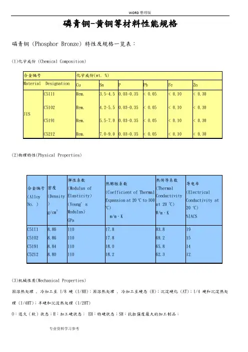
磷青铜-黄铜等材料性能规格磷青铜 (Phosphor Bronze) 特性及规格一览表:(1)化学成份 (Chemical Composition)(2)物理特性(Physical Properties)热膨胀系数(Coefficient of ThermalExpansion at 20 oC to 300 oC)m/m .K 热传导系数(ThermalConductivityat 20 W/m(3)机械性质(Mechanical Properties)固溶热处理 , 冷加工至 1/8 硬 (1/8H);固溶热处理 , 冷加工至硬态 (H);沉淀硬化 (AT);1/4 硬和沉淀热处理 (1/4HT);半硬和沉淀热处理 (1/2HT)O :退火(软)状态;H :加工硬状态; EH :特硬状态;SH :抗拉强度最大的加工制品;Mechanical Properties (continuous)黄铜 (Brass) 特性及规格一览表:(1)化学成份 (Chemical Composition)(2)物理特性(Physical Properties)热膨胀系数(Coefficient of Thermal Expansion at 20 oC to 300oC) m/m .K热传导系数(ThermalConductivity at 20 W/m(3)机械性质(Mechanical Properties)C194合金(HSM Copper)特性及规格一览表:(1)化学成份(Chemical Composition)(2)物理特性(Physical Properties)热膨胀系数(Coefficient of ThermalExpansion at 20 o C to 300 o C)m/m.K 热传导系数(Thermal Conductivity at 20W/m(3)机械性质(Mechanical Properties)红铜 (Copper) 特性及规格一览表:(1)化学成份(Chemical Composition)(2)物理特性(Physical Properties)热膨胀系数(Coefficient of Thermal Expansion at 20 oC to 300oC) m/m .K热传导系数(ThermalConductivity at 20 W/m(3)机械性质(Mechanical Properties)磷青铜(Phosphor Bronze)合金各规格对照表铜合金板材厚度公差 (Thickness tolerances for strip): 红铜 (C1100、C1200、C1220)黄铜 (C2600、C2680、C2801)磷青铜 (C2600、C2680、C2801)特殊铜合金 (C194)铜合金板材宽度公差 (Width tolerances for strip):铜合金板材蛇弯度公差 (Permissible max. value on camber):* Dimensional tolerances shall be in accordance with JIS H3100。
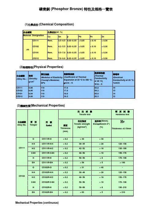
磷青銅 (Phosphor Bronze) 特性及規格一覽表(1)化學成份(Chemical Composition)(2)物理特性(Physical Properties)(3)機械性質(Mechanical Properties)Mechanical Properties (continuous)黃銅 (Brass) 特性及規格一覽表(1)化學成份(Chemical Composition)(2)物理特性(Physical Properties)(3)機械性質(Mechanical Properties)C194合金(HSM Copper)特性及規格一覽表(1)化學成份(Chemical Composition)(2)物理特性(Physical Properties)(3)機械性質(Mechanical Properties)紅銅 (Copper) 特性及規格一覽表(1)化學成份(Chemical Composition)(2)物理特性(Physical Properties)(3)機械性質(Mechanical Properties)磷青銅(Phosphor Bronze)合金各規格對照表銅合金板材厚度公差(Thickness tolerances for strip) 銅合金板材寬度公差(Width tolerances for strip):紅銅(C1100、C1200、C1220)黃銅(C2600、C2680、C2801)磷青銅(C2600、C2680、C2801)特殊銅合金(C194)銅合金板材蛇彎度公差(Permissible max. value on camber):* Dimensional tolerances shall be in accordance with JIS H3100。
磷青銅(Phosphor Bronze) 特性及規格一覽表:(1)化學成份(Chemical Composition)(2)物理特性(Physical Properties)(3)機械性質(Mechanical Properties)Mechanical Properties (continuous)黃銅(Brass) 特性及規格一覽表:(1)化學成份(Chemical Composition)(2)物理特性(Physical Properties)(3)機械性質(Mechanical Properties)C194合金(HSM Copper)特性及規格一覽表:(1)化學成份(Chemical Composition)(2)物理特性(Physical Properties)(3)機械性質(Mechanical Properties)紅銅(Copper) 特性及規格一覽表:(1)化學成份(Chemical Composition)(2)物理特性(Physical Properties)(3)機械性質(Mechanical Properties)磷青銅(Phosphor Bronze)合金各規格對照表銅合金板材厚度公差(Thickness tolerances for strip):紅銅(C1100、C1200、C1220)黃銅(C2600、C2680、C2801)磷青銅(C2600、C2680、C2801)特殊銅合金(C194)銅合金板材寬度公差(Width tolerances for strip):銅合金板材蛇彎度公差(Permissible max. value on camber):* Dimensional tolerances shall be in accordance with JIS H3100。
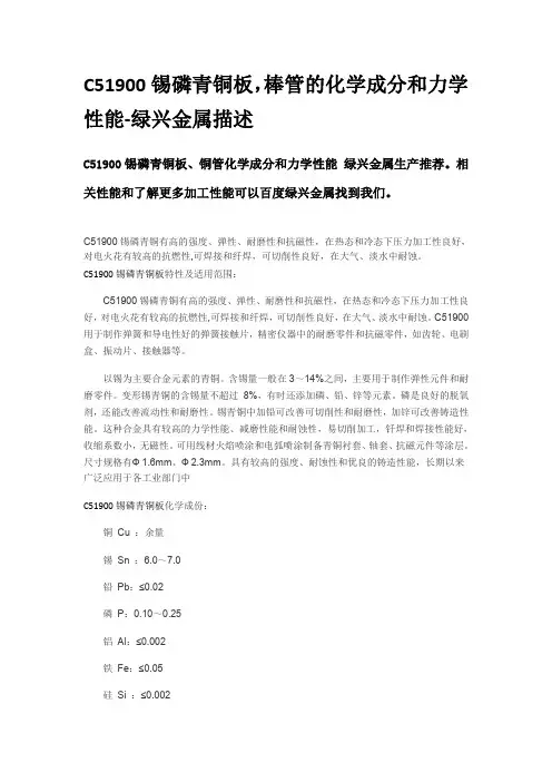
C51900锡磷青铜板,棒管的化学成分和力学性能-绿兴金属描述C51900锡磷青铜板、铜管化学成分和力学性能绿兴金属生产推荐。
相关性能和了解更多加工性能可以百度绿兴金属找到我们。
C51900锡磷青铜有高的强度、弹性、耐磨性和抗磁性,在热态和冷态下压力加工性良好,对电火花有较高的抗燃性,可焊接和纤焊,可切削性良好,在大气、淡水中耐蚀。
C51900锡磷青铜板特性及适用范围:C51900锡磷青铜有高的强度、弹性、耐磨性和抗磁性,在热态和冷态下压力加工性良好,对电火花有较高的抗燃性,可焊接和纤焊,可切削性良好,在大气、淡水中耐蚀。
C51900用于制作弹簧和导电性好的弹簧接触片,精密仪器中的耐磨零件和抗磁零件,如齿轮、电刷盒、振动片、接触器等。
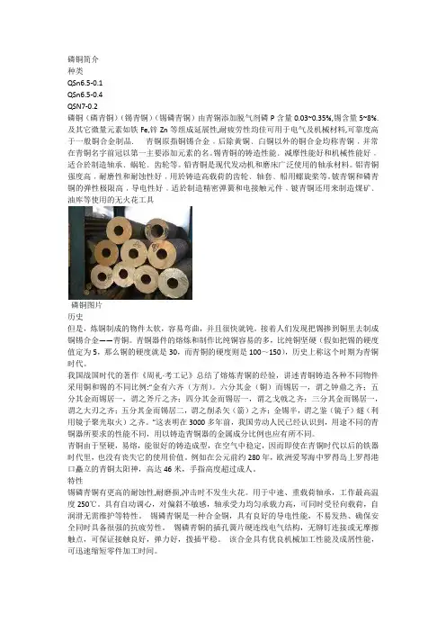
以锡为主要合金元素的青铜。
含锡量一般在3~14%之间,主要用于制作弹性元件和耐磨零件。
变形锡青铜的含锡量不超过8%,有时还添加磷、铅、锌等元素。
磷是良好的脱氧剂,还能改善流动性和耐磨性。
锡青铜中加铅可改善可切削性和耐磨性,加锌可改善铸造性能。
这种合金具有较高的力学性能、减磨性能和耐蚀性,易切削加工,钎焊和焊接性能好,收缩系数小,无磁性。
可用线材火焰喷涂和电弧喷涂制备青铜衬套、轴套、抗磁元件等涂层。
尺寸规格有Ф1.6mm、Ф2.3mm。
具有较高的强度、耐蚀性和优良的铸造性能,长期以来广泛应用于各工业部门中C51900锡磷青铜板化学成份:铜Cu :余量锡Sn :6.0~7.0铅Pb:≤0.02磷P:0.10~0.25铝Al:≤0.002铁Fe:≤0.05硅Si :≤0.002锑Sb :≤0.002铋Bi:≤0.002注:≤0.1(杂质)C51900锡磷青铜板力学性能:抗拉强度σb (MPa):≥470伸长率δ5 (%):≥13注:棒材的纵向室温拉伸力学性能试样尺寸:直径或对边距离5~12热处理规范:热加工温度750~770℃;退火温度600~650℃。
C51900锡磷青铜板特性锡青铜除了含有3%~14%锡,此外还常常加入磷、锌、铅等元素。
磷青銅材料性能規格磷青銅(Phosphor Bronze) 特性及規格一覽表:(1)化學成份(Chemical Composition)(2)物理特性(Physical Properties)(Young’s Modulus)熱膨脹係數(Coefficient of ThermalExpansion at 20 o C to300 o C)m/m.K熱傳導係數(ThermalConductivityat 20W/m(3)機械性質(Mechanical Properties)固溶熱處理, 冷加工至1/8 硬(1/8H);固溶熱處理, 冷加工至硬態(H);沉澱硬化(AT);1/4 硬和沉澱熱處理(1/4HT);半硬和沉澱熱處理(1/2HT)O:退火(軟)狀態;H:加工硬狀態;EH:特硬狀態;SH:抗拉強度最大的加工製品;磷青銅(Phosphor Bronze)合金各規格對照表銅合金板材厚度公差(Thickness tolerances for strip):磷青銅(C2600、C2680、C2801)銅合金板材寬度公差(Width tolerances for strip):銅合金板材蛇彎度公差(Permissible max. value on camber):* Dimensional tolerances shall be in accordance with JIS H3100合金種類含錫丹銅磷青銅C4250C4250M C5050C5111C5102C5191C5210化性成份(%)銅:87~90.錫:1.5~3.0鋅:餘量銅:86~88錫:2.5~4.鋅:餘量銅:餘量.錫:1.0~1.7磷:0.004~0.01銅:餘量.錫:3.5~4.9磷:0.11~0.13銅:餘量.錫:4.5~5.5磷:0.11~0.13銅:餘量.錫:5.5~7.0磷:0.11~0.13銅:餘量.錫:7.0~9.0磷:0.15~0.17比重(gm/cm3)8.7 88.788.898.868.868.838.80熱膨脹係數(10-6/℃)18.518.517.817.817.81818.2熱傳導係數(Cal/cm2/cm/sec/℃)0.290.250.490.200.170.160.15導電率(%IACS, 20℃)≧26≧24≧45≧20≧20≧13≧12抗張強度(N/mm 2)燒燉軟化295~380≧245≧245≧295≧300310~395--1/4H340~405340~405--345~440370~470395~490--1/2H390~475390~475360~425410~510470~570490~590470~610 3/4H430~510430~510----------H480~565480~565390~470490~590570~670525~670585~710 EH525~605525~605440~510≧570≧615≧670635~735 SH580~650580~650≧490------≧725 ESH≧635≧635----------伸長率(%)燒燉軟化≧35≧40≧25≧38≧40≧42--1/4H≧25≧30--≧25≧28≧35--1/2H≧15≧20≧15≧12≧15≧20≧27 3/4H≧10≧15----------H≧5≧10≧5≧7≧7≧10≧20 EH----≧2≧3≧4≧5≧11 SH------------≧9。
Trans.Nonferrous Met.Soc.China31(2021)692−702Microstructural characterization of blanked surface of C5191phosphor bronze sheet under ultra-high-speed blankingDao-chun HU1,2,Ming-he CHEN2,Lei WANG2,3,Hong-jun WANG11.Engineering Technology Training Center,Nanjing Vocational University of Industry Technology,Nanjing210023,China;2.Jiangsu Key Laboratory of Precision and Micro-Manufacturing Technology,Nanjing University of Aeronautics and Astronautics,Nanjing210016,China;3.School of Mechanical Engineering,Nanjing Vocational University of Industry Technology,Nanjing210023,ChinaReceived3March2020;accepted10November2020Abstract:The deformation mechanism of C5191phosphor bronze sheet under ultra-high-speed blanking was investigated.By virtue of a DOBBY-OMEGA F1ultra-high-speed press,the ultra-high-speed blanking test was conducted on C5191phosphor bronze sheets with a thickness of0.12mm at3000strokes per minute.The microstructures of the blanked edges were characterized and analyzed separately by electron back-scatter diffraction (EBSD)and transmission electron microscopy(TEM).The results show that grains in the blanked edges are stretched along the blanking direction.Strong{001}〈100〉cube textures(maximum pole densities of9and12,respectively)and secondarily strong{011}011〈〉textures(maximum pole densities of4and7,respectively)are formed in local zones. Additionally,deformation twins are found in the shear zone of the blanked edges which are rotated and coarsened due to the blanking-induced extrusion and local thermal effect which can further form into sub-grains with clear and high-angle boundaries.The C5191phosphor bronze sheet is subjected to adiabatic shear during ultra-high-speed blanking,accompanied with dynamic recrystallization.Key words:C5191phosphor bronze;ultra-high-speed blanking;blanked surface;adiabatic shear;dynamic recrystallization1IntroductionMetal workpieces in information technology (IT)devices including connector terminals in computer,communication and consumer electronics (3C)products,lead frames of integrated circuits, aerospace electrical connectors,and connectors for high-speed data transmission of car on internet in the era of big data.These workpieces are all characterized by ultra-thin thickness(lower than 500μm),complex shapes,small sizes,high requirements on size and location precision(nearly micron-order)and high demand[1].Products are required to integrate an increasingly number of functions and show high performance.They are becoming smaller,while exhibit more elaborated appearance and have a more frequent upgrading rate due to very high demand in the market.The workpieces have massive increasing demands on low-cost and good quality,which generally requires manufacturing in large quantities using high-speed and precision progressive stamping technology.Blanking is considered as the most fundamental and frequently used process in high-speed and precision progressive stamping.It can not only be used to manufacture blanks in the early period for the subsequent processes such asCorresponding author:Ming-he CHEN;Tel:+86-25-84892508;E-mail:******************.cn DOI:10.1016/S1003-6326(21)65530-91003-6326/©2021The Nonferrous Metals Society of China.Published by Elsevier Ltd&Science PressDao-chun HU,et al/Trans.Nonferrous Met.Soc.China31(2021)692−702693bending and drawing,but also be used as the finalprocess to directly shape and manufacture preciseblanked parts.The blanked edges determine the quality of blanked parts.During the whole processof blanking,plastic deformation,fracture andseparation of metal materials are only found in alocalized zone around the cutting edges.The cuttingedges were subjected to huge vertical and lateralpressures,and those high pressures will produce a large quantity of friction heat.Moreover,the blanking process continuously lasts for a long time, which results significant local temperature-rise and softening effect[2,3].Additionally,the strain-rate hardening and strain hardening of materials under a high rate and large strain make the fracture mechanism of high-speed precise blanking more complex.Also,due to the constraints of service conditions(such as low fracture zones,short response time and difficulty in on-line detection),it is hard to quantitatively describe the characteristics of blanked edges.MUCHA[4]and ACHOURI et al[5]separately acquired microstructures such as the sizeof grains on the blanked edges and the streamlinedistribution of metals.They found that thesignificant plastic deformation occurs and grainsare greatly refined in the blanked edges.ISMAIL et al[6]obtained the curve of yield stress on the blanked edges of non-oriented silicon steel with a thickness of0.65mm at the blanking speed of SPM80by using nano-indentation technology.The results indicated that significant work-hardening occurs in the zone around the blanked edges at a low blanking speed.GAUDILLIERE et al[7]performed high-speed blanking(14.6m/s)on C40steel using thesplit Hopkinson pressure bar test,and observed anadiabatic shear band in the blanked edges.SAPANATHAN et al[8]found that ultra-fine grains (diameter of grains lower than1μm)appeared in the microzone of the edges after attaining a crystal orientation map of the blanked edges of aluminum/ copper composite materials using the electron back-scatter diffraction(EBSD)technology.Using the finite element technology, RAFSANJANI et al[9]explored the temperature change of X30Cr13steel in the blanking process (blanking clearance of c=10%and punching speed of V=1000mm/s).They found that the localtemperature of the blanked edges is as high as387°C.By numerically simulating the high-speed blanking process(thickness of t=0.12mm,blankingclearance of c=6.5%t and punching speed of V=1000mm/s)of C5191phosphor bronze sheets, HU et al[10]demonstrated that the local temperature of the blanked edges reaches444°C. Local temperature rise has a significant effect on the fracture damage induced by blanking and microstructures of the blanked edges.Current research further systematicallyexplores various aspects of blanking such asmacroscopic blanked edge quality and numericalsimulation to deepen the understanding on high-speed blanking.However,it is difficult to profoundly and effectively analyze the blanking mechanism as little is known about the control and effects of microstructures that play critical roles on the localization of macroscopic deformation during blanking.In this study,the microstructural characteristics of the blanked edges and their evolution were investigated by conducting high-speed blanking tests.The results provide a basis for exploring the fracture mechanism of sheets during high-speed blanking.2Experimental2.1Preparation of blanking samplesTo describe the preparation process of theblanking samples for micro-measurements,theblanking sample is illustrated in Fig.1.Based on the micro-measurement of the blanked edges,the microstructure evolution of shear zone under different blanking conditions was analyzed(Zone I). The microscopic evolution of materials from the blanked edges to the matrix was analyzed based on the longitudinal section perpendicular to the direction of the blanked edges(Zone II).2.2Preparation of EBSD samplesEBSD technology is an effective method thatcan be used to determine crystal structure,orientation and related crystallographic information of samples.The diffraction Kikuchi band excited by electron beams emitted from the SEM on the surface of inclined samples was analyzed[11,12].Dao-chun HU,et al/Trans.Nonferrous Met.Soc.China 31(2021)692−702694The orientation analysis based on EBSD technology can acquire abundant information on the inner structure of crystals.It is common that only grain size,shape and distribution can be attained from microstructural and morphological images.Even though the image is processed using an image analysis system,only the quantitative information on morphology can be obtained.In contrast,in addition to diverse information on morphology,orientation imaging microscopy (OIM)can acquire various types of quantitative information such as grain orientation,phase distribution,grain (phase)boundary type,strain distribution and dislocation density [13,14].EBSD technology can demonstrate more information compared with direct observations.This information is crucial for comprehensively exploring the deformation law and microscopic mechanism of materials.Due to the requirement of the surface roughness requirement of samples in the EBSD test,the samples failed to be prepared in Zone I.To acquire the microstructures of deformed materials in Zone II on the blanked edges,blanking strips were cut and embedded in conductive inlay powder,as shown in Fig.2.The ends (marked in Fig.2(a))of the embedded samples all corresponded to the cutting planes (Fig.2(b))of the blanked edges.The surface stress layer was removed using twin-jet electropolishing after being mechanically polished.The scanning area of EBSD was 15μm from the blanked edges,as shown in Fig.2(b).The EBSD test was completed using a JSM−7001F/JEOL field emission scanning electron microscope equipped with EBSD.2.3Preparation of samples for TEM testTo test and analyze the microstructures of the blanked edges,and further discuss the evolution law of microstructures during blanking,two sample preparation methods were adopted.TEM samples perpendicular to the blanked edges (for observing microstructural changes from the blanked edges to the material matrix)and parallel to the edges (for observing the microstructures of the shear zone)were attained respectively,as shown in Fig.3.When preparing TEM samples perpendicular to the blanked edge,a disk with d 1.5mm was first obtained at the proper location of the blanked strip,as shown in Fig.3(a).The blanked edges of two semicircular samples were bonded (bonding the shear zone with the shear zone)and fixed using copper rings (Fig.3(b)).The blanked strip was subjected to one-way selective thinning by applying a Gatan PIPS−691ion milling,firstly from the shear zone along the fracture zone and then from the direction of the roll over zone.In this process,the position was broken down due to thinning in the shear zone (Fig.3(b)).Finally,the microzone forFig.1Schematic map of blankingsampleFig.2Preparation of samples for EBSD analysis:(a)Embedded blanked-sample;(b)Cutting plane of blanked edgesDao-chun HU,et al/Trans.Nonferrous Met.Soc.China31(2021)692−702695 Fig.3Preparation of TEM samples:(a,d)TEM sample preparation area;(b,e)Fixed by copper ring;(c,f)TEM observing area(III:TEM samples of longitudinal section;IV:TEM samples of blanked surface)the TEM test was situated within the red borderarea in Fig.3(c)to acquire the TEM morphologiesof four local microzones,near the shear zone,adjacent to the shear zone,adjacent to the matrix,and in the matrix.To ensure that the positions of the microzones(box zone)in different blanked stripsfor TEM test were consistent,the same parametersetting was adopted during one-way selectiveion-thinning.To reveal the evolution of the microstructuresin shear zones on the blanked edges at different punching speeds,TEM samples parallel to the blanked edges were prepared by referring to the preparation method[15]according to the following process:multiple samples were cut from the blanked strips that were3mm in length and about 0.3mm in width,as shown in the red border area of Fig.3(d)(the blanked edge cannot be damaged). Multiple samples were bonded with(G1)glue to ensure evenness of the blanked edges and fixed using copper rings(Fig.3(e)).The blanked strips were subjected to one-way selective thinning using the Gatan PIPS691ion beam thinner,only from the opposite of the blanked edges until the sample was broken down(Fig.3(e)).The microzones for the TEM test are displayed in Fig.3(f).The JEM−2100F/JEOL high-resolution TEM was usedto characterize the blanked edges.3Results and discussion3.1EBSD analysis of blanked edgesThe EBSD technology can be used to obtainthe microstructures of blanked edges and theirsurrounding zones to provide abundant informationabout the evolution of microstructures in theblanking process.Figure4(a)shows the image quality(IQ)of EBSD patterns in the deformed zoneof the blanked edge.According to the scanninginformation of the orientation mapping ofmicrozones,the quality of Kikuchi lines obtained inthe zone was demonstrated using different grayscales.However,the distortion and deformation of the crystals within the diffraction zone due to the effect of residual strain decrease the quality of EBSD patterns so that the IQ map is able to qualitatively reflect the distribution conditions of strains within the microstructures[16].Plastic deformation leads to the occurrence of a large number of dislocations in metal grains,whilst lattice distortion around the dislocation accumulates with the growth of dislocations.During the violentDao-chun HU,et al/Trans.Nonferrous Met.Soc.China31(2021)692−702 696Fig.4Orientation map of deformed zone on blanked edges(SPM600):(a)IQ map;(b)Local average misorientationdeformation,small-angle orientation changesappear in the local zones of materials to formvarious substructures including dislocation walls,microzones and even sub-grains.The orientationchange of local zones within metal grains under large deformation reflects the accumulation of thedislocations[17,18].The local averagemisorientation(Fig.4(b))attained based on theEBSD technology is sensitive to the subtle changeof orientation in grains,which can qualitativelymeasure the relative dislocation density of deformed metals[19].It can be seen that a large number of geometrically necessary boundaries (GNBs)and incidental dislocation boundaries (IDBs)are formed in the deformed zone of the blanked edges during the blanking.The grains in the zone are subjected to violent plastic deformation and stretched along the blanking direction to form strip-shaped microstructures,with a large misorientation of grains.In this case,a fragmentation layer of grains is formed.However, many high-angle GNBs for coordinating different strain zones have evolved into grain boundaries, and occupied a major proportion of the near shear zone.With the proceeding of blanking,grains are rotated so that the orientations of some grains are gradually consistent to form a special preferred orientation.The misorientation and size of grains in the blanked edges at a high punching speed are shown in Fig.5.It can be seen that the proportion of grains with high-angle orientation greatly increases in the blanked edge,and also fine grains with a small size are mainly found.This indicates that at an ultra-high punching speed,the local zone of the blanked edges presents a relatively low dislocation density(low local average misorientation),where micro-crystals(at the submicron order)are present.Furthermore,a large number ofhigh-angleFig.5Misorientation and size of grains in blanked edges at ultra-high punching speed:(a)Misorientation angle of blanked surface;(b)Grain size of blanked surfaceDao-chun HU,et al/Trans.Nonferrous Met.Soc.China31(2021)692−702697boundaries(large misorientation)are formed, accompanied with a certain preferred orientation (that is,special texture)of grains.Using Eulerian angles defined by Bunge,the random crystal orientation was realized by rotating from the initial orientation byφ1,Φandφ2,which were set in the range of0°−90°.The characteristic map of Euler orientation based onφ2at the interval of5°was selected to establish the orientation distribution function(ODF)for describing the textures of the diffraction microzones.According to the information shown in the pole figure(PF)and inverse pole figure(IPF),the textures of the blanked edges are shown in Fig.6.Through analysis using the INCA crystal software,strong{001}〈100〉cube textures (maximum pole densities of9and12)and secondarily strong{011}011〈〉textures(maximum pole densities of4and7)are formed on the blanked edges(SPM3000)at an ultra-high punching speed. According to the theory of orientation-induced nucleation,grains with the cubic orientation exhibit an advantage in the number of nucleation and grain size relative to grains with the other orientations.In contrast,cube textures are easily affected by various factors including nucleation and high-angle boundary migration,and are formed due to recrystallization annealing[20,21].Therefore,more {001}〈100〉cube textures are formed on the blanked edges at an ultra-high punching speed.3.2TEM characterization of blanked edgesAs described above,to determine the evolution of microstructures in the blanked edges and their surrounding deformed zone,Sample III perpendicular to the blanked edges was prepared by using the preparation method of planar samples and was observed.The TEM microstructures are shown in Fig.7.It can be seen that the blanked edge and its surrounding deformed zone show very different microstructural characteristics.Grains in the Zone A adjacent to the blanked edges were obviously stretched along the blanking direction under the combined effect of pressures and shear stress to form elongated grains with large deformation.The zone undergoes more significant deformation than the surrounding Zones B,C and D.After grains stretch to form the elongated thick-wall dislocation cells,dislocation of the cell walls increases and becomes entangled to form a dislocation wall. Furthermore,the dislocation wall collapses to form multiple sub-grains with a low misorientation underFig.6Textures of deformed zone in blanked edges:(a)ODF map;(b)PF map;(c)IPF mapDao-chun HU,et al/Trans.Nonferrous Met.Soc.China31(2021)692−702698Fig.7TEM images of blanked edges and corresponding affected zones:(a)Sample III(perpendicular to blanked surface);(b)Zone A;(c)Zone B;(d)Zone C;(e)Zone Dthe effect of heat.With the proceeding of blanking induced deformation,a small equiaxed zone is formed through rotation of sub-grains at the sub-boundary.In the subsequent deformation process,the dislocations climb and unlike dislocations on the sub-boundary,are mutually offset and disappear[22,23].There are many ultra-fine grains in the Zone A,with a grain size of 50−100nm.The diffraction patterns of the selected area also show distinct rings,which conform to EBSD characterization results that many high-angle boundaries in the Zone A.Some ultra-fine grains exhibit clear boundaries and low internal dislocation density.Thus,it can be inferred that the grains are typically formed by dynamic recrystallization[24].It was also found that the diffraction patterns of selected Zones D to A of the samples change from the discrete points to the discontinuous rings.These observations indicate that grains are constantly refined and the misorientation of grains constantly increases with the increase of strain.According to the rotational dynamical recrystallization(RDR)of sub-grains proposed by NESTCRCNKO and MEYERS[25],TEM was utilized to observe microstructures of the ultra-high-speed blanked edge.It was found that dislocation cells and tangles on the blanked edges constantly absorb dislocations under combined effects of large strain,plastic deformation at a high strain rate and temperature rise to transform into sub-grains and grains.On this condition,sub-boundaries are generated which form high-angle grain boundaries through short-distance movement.Dao-chun HU,et al/Trans.Nonferrous Met.Soc.China 31(2021)692−702699Moreover,sub-grains are stretched,broken and rotated under the effects of ultra-high strain,thus further from nano-crystals (Fig.8(b)).Fig.8Microstructures of adjacent area of blanked edges at ultra-high punching speed:(a)TEM morphology;(b)Nano-grains morphology;(c)Diffraction spots of nano-grainsFrom the diffraction patterns in the re-crystallized zone,it can be seen that the diffraction ring is more intact and smoother,and the number of layers of the ring is also more (Fig.8(c)).The results indicate that there is a large misorientation between grains consisting of high-angle boundaries,instead of sub-boundaries.Additionally,due to the thermal softening effect caused by local high temperature,the local zone is subjected to more violent plastic deformation.In this case,adiabatic shear is likely to occur to form adiabatic shear characterized by dynamic recrystallization [26,27].To further elucidate the evolution of microstructures in the shear zone on the blanked edges,Sample IV of the shear zone was prepared using the method for preparing cross-section samples.TEM observations of microstructures are displayed in Fig.9.It can be clearly seen that the grain size of the shear zone (Sample IV)is larger than that of the zone (Sample III)near the shear zone,perpendicular to the direction of the blanked edges.This implies that grains stretch along the blanking direction.It can also be found that a unique type of deformation twins occurred in the shear zone in the blanked edges.C5191phosphor bronze belongs to a face-centered cubic system,which has many slip systems and the deformation was mainly in the form of slip.However,the blanked edge was instantaneously subjected to a large shear stress during ultra-high-speed blanking.Under these conditions,the dislocation density significantly increased.Dislocations are entangled and piled to form a dislocation wall,thus delaying the initiation of the slip system.In this case,the occurrence of twins can compensate for the deficiency of the number of slip systems to satisfy the demand of great deformation [28,29].The twin boundaries in the figure are not straight but bend to some extent,which implies that lattice distortion is generated around the twin boundary.Moreover,a certain polygonization process occurs in and around the twins [30,31].With increasing blanking speed,more dislocation motions occur in the grains.The dislocation motion is hindered by the grain boundary to cause the piling up of a large number of dislocations in the vicinity of the grain boundary,thus forming new sub-grains.The newly generated sub-grains will then evolve into the structures with a high-angle grain boundary when the blanking speed is furtherincreased.Fig.9Microstructures of shear zoneDao-chun HU,et al/Trans.Nonferrous Met.Soc.China31(2021)692−702 700The dislocations are gradually entangled and converged to form the dislocation cell in theblanking process.As the blanking-induced deformation continues to grow,the dislocation cells grow in quantity whilst decreasing in size.Furthermore,the dislocation density of the cell wall further increases with the cell wall constantly moving to the grain boundary.Eventually,thedislocation tangles in the cell wall constantly converge resulting in the collapse of the dislocation cells,thus forming low-angle grain boundaries.Alarge number of sub-micro-scale unstable sub-grains are found in grains and small-angle textures rotate under the extrusion effects inducedby blanking of deformation.Furthermore,twins and sub-grains are broken,extruded and kinked,so numerous crystal defects are entangled andconverged to generate high distortion energy. Additionally,the sub-grains are gradually coarsened under the temperature-rise effect to form sub-grainswith apparent and high-angle boundaries.The sub-grains continue to grow as a crystal nucleus for recrystallization and finally grains are coarsened tohave significantly larger sizes than that of grains in the zone of Sample III.4Conclusions(1)Grains in the edges of C5191phosphorbronze sheets subjected to ultra-high-speedblanking undergo significant plastic deformation,which are stretched along the blanking direction toform strip-shaped microstructures.The misorientation of grains increases and thefragmentation layer of grains is formed.As theblanking process proceeds,grains are rotated,andso the orientations of some grains are graduallyconsistent to form a special{001}〈100〉cubetexture.(2)Diffraction patterns in the zones adjacent tothe blanked edges with different distances changefrom discrete points to discontinuous rings,showing different microstructural characteristics.There are many ultra-fine grains with the size of50−100nm in the Zone A adjacent to the blanked edges.In the zone,diffraction patterns appear as distinct rings,with clear grain boundaries and low internal dislocation density,indicating that they are typical grains formed by dynamic recrystallization.(3)Deformation twins are found in the shear zone of the blanked edges and are rotated and coarsened under the blanking-induced extrusion effect and local temperature-rise effect,which further form sub-grains with clear and high-angle boundaries.(4)During ultra-high-speed blanking,the local zone of the blanked edges is subjected to adiabatic shear due to high-speed deformation and adiabatic temperature rise,accompanied with dynamic recrystallization.This result suggests a new mechanism which largely differs from the common blanking mechanism. AcknowledgmentsThe authors are grateful for the financial supports from Jiangsu Key Laboratory of Precision and Micro-manufacturing Technology of China (JSJMYWX2020-01),Zhejiang Provincial Natural Science Foundation of China(LY18E050005)and the Startup Foundation for Introducing Talent of Nanjing Institute of Industry Technology (YK18-13-02)of China.References[1]SUBRAMONIAN S.Improvement of punch and die life andpart quality in blanking of miniature parts[D].Columbus: The Ohio State University,USA,2013:1−6.[2]GULCIMEN BÇ,SOYARSLAN C,BARGMANN S,HAHNER P.Experimental and computational study of ductile fracture in small punch tests[J].Materials,2017,10: 1185−1204.[3]MORIN D,HOPPERSTAD O S,BENALLAL A.On thedescription of ductile fracture in metals by the strain localization theory[J].International Journal of Fracture, 2018,209:1−25.[4]MUCHA J.An experimental analysis of effects of variousmaterial tool’s wear on burr during generator sheets blanking [J].International Journal of Advanced Manufacture Technology,2010,50:495−507.[5]ACHOURI M,GILDEMYN E,GERMAIN G,SANTO P D,POTIRON A.Influence of the edge rounding process on the behaviour of blanked parts:Numerical predictions with experimental correlation[J].International Journal of Advanced Manufacture Technology,2014,71:1019−1032.[6]ISMAIL A B,RACHIK M,MAZERAN P E,FAFARD M,HUG E.Material characterization of blanked parts in the vicinity of the cut edge using nanoindentation technique and inverse analysis[J].International Journal of Mechanical Sciences,2009,51:899−906.Dao-chun HU,et al/Trans.Nonferrous Met.Soc.China31(2021)692−702701[7]GAUDILLIERE C,RANC N,LARUE A,MAILLARD A,LORONG P.High speed blanking:An experimental method to measure induced cutting forces[J].Experimental Mechanics,2013,53:1117−1126.[8]SAPANATHAN T,IBRAHIM R,KHODDAM S,ZAHIRI SH.Shear blanking test of a mechanically bonded aluminum/copper composite using experimental and numerical methods [J].Materials Science and Engineering A,2015,623: 153−164.[9]RAFSANJANI A,ABBASION S,FARSHIDIANFAR A,IRANI N.Investigation of the viscous and thermal effects on ductile fracture in sheet metal blanking process[J].International Journal of Advanced Manufacture Technology, 2009,45:459−469.[10]HU Dao-chun,CHEN Ming-he,OUYANG Jin-dong,YINLi-ming.Finite element analysis of the thermal effect in high-speed blanking of thick sheet metal[J].International Journal of Advanced Manufacture Technology,2015,80: 1481−1487.[11]WISNIEWSKI W,RUSSEL C.An experimental viewpointon the information depth of EBSD[J].Scanning,2015,9: 2921−2924.[12]CHEN Shao-kai,LI Qing-yu,ZHUANG Miao,XU Fei.EBSD and its application in materials research[J].Rare Metal Materials and Engineering,2006,35:500−504. [13]WILKINSON A,BRITTON T,JIANG J,MEADEN G,DINGLEY D.High accuracy EBSD:A review of recent applications,innovations,and remaining challenges[J].Microscopy Microanalysis,2011,17:402−403.[14]WRIGHT S I,NOWELL M M,KLOE R D,CAMUS P,RAMPTON T.Electron imaging with an EBSD detector[J].Ultramicroscopy,2015,148:132−145.[15]MA Xiu-mei,YOU Li-ping.Simple preparation method forTEM cross-sectional specimens of thin-film materials[J].Journal of Chinese Electron Microscopy Society,2015,34: 359−362.(in Chinese)[16]HUANG Ya-ming,PAN Chun-xu.Micro-stress−strainanalysis in materials based upon EBSD technique:A review [J].Journal of Chinese Electron Microscopy Society,2010, 29:1−11.(in Chinese)[17]CAO W Q,GODFREY A,LIU Q.Determining dislocationcell sizes for high-strain deformation microstructures using the EBSP technique[J].Journal of Microscopy,2003,211: 219−229.[18]HUMPHREYS F J,BATE P S,HURLEY P J.Orientationaveraging of electron backscattered diffraction data[J].Journal of Microscopy,2001,201:50−58.[19]MENG Yang,REN Qun,JU Xin-hua.Evaluation ofdislocation density by local grain misorientation in deformed metals[J].Transactions of Materials and Heat Treatment, 2014,35:122−128.(in Chinese)[20]CHEN Fang-fang.Influence of recrystallization texture onmechanical property of aluminum alloy sheets[D].Tianjing:Hebei University of Technology,China,2007:20−35.(inChinese)[21]XU Jin,MAO Wei-min,FENG Hui-ping,SHU Long-wei.Influence of annealing process on cube texture formation inaluminum foil of high voltage anode electrolytic capacitor[J].The Chinese Journal of Nonferrous Metals,2001,11:42−46.(in Chinese)[22]ALAWADHI M Y,SABBAGHIANRAD S,WANG Y C,HUANG Y.Characteristics of grain refinement inoxygen-free copper processed by equal-channel angularpressing and dynamic testing[J].Materials Science andEngineering A,2020,775:1−8.[23]WANG Song-wei,ZHANG Shi-hong,SONG Hong-wu,CHEN Yan.Evolution of microstructure of TP2copper tube during drawing process[J].The Chinese Journal ofNonferrous Metals,2019,29(4):782−789.(in Chinese) [24]TOMCZYK A,SEWERYN A,GRADZKA-DAHLKE M.The effect of dynamic recrystallization on monotonic andcyclic behaviour of Al−Cu−Mg alloy[J].Materials,2018,11: 874−892.[25]NESTERENKL V F,MEYERS M A,LASALVIA J C,BONDAR M P,CHEN Y J,LUKYANOV Y L.Shear localization and recrystallization in high-strain,high-strain-rate deformation of tantalum[J].Materials Science andEngineering A,1997,229:23−41.[26]LI Guo-ai.Deformation behaviors and microstructure changeof several metals under high velocity impact conditions[D].Harbin:Harbin Institute of Technology,China,2005:80−84.(in Chinese)[27]WANG Yan-fei,WANG Ming-sai,YIN Kun,HUANGAi-hui,LI Yu-sheng,HUANG Cong-xiang.Yielding andfracture behaviors of coarse-grain/ultrafine-grainheterogeneous-structured copper with transitional interface[J].Transactions of Nonferrous Metals Society of China,2019,29(3):588−594.[28]ZHOU Jun,WANG Zhi-fa,CUI Da-tian,JIANG Guo-sheng.Microstructure of shearing plane and new method forrefining grains technology in sheets[J].The Chinese Journalof Nonferrous Metals,2008,18:266−270.(in Chinese) [29]ZHANG Xue-hui,LI Xiao-xian,LIU Wei-jiang,YANG Kai,ZHU Sheng-jian,JIANG Miao.Effect of cold deformation on microstructures and properties of Al2O3-dispersionstrengthened copper[J].The Chinese Journal of NonferrousMetals,2018,28(4):705−711.(in Chinese)[30]YANG Yang,LIAN Xiao-long,WANG Jun-liang.Effect ofthe grain boundary character distribution on theself-organization of adiabatic shear bands in1Cr18Ni9Tiaustenitic stainless steel[J].Journal of Materials Science,2019,54:7256−7270.[31]RYABOV P N,KUDRYASHOV N A,MURATOV R V.Adiabatic shear bands localization in materials undergoingdeformations[J].Journal of Physics:Conference Series,2017,788:1−4.。
低温退火对锡磷青铜 C5191组织和机械性能的影响徐灏;朱协彬;宣夕文;罗继华【摘要】After homogenization heat treatment,the Tin Phosphor Bronze C5 1 91 was tested under differ-ent low temperature.The material structure was characterized by optical microscopy.The mechanical properties were tested by electronic universal machine and the influences between heat treatment tem-perature and mechanical properties of Tin Phosphor Bronze C5 1 91 was discussed.The results showed that,compared with the untested C5 1 91,the yield strength of C5 1 91 which temperature were at 230 ℃, 220 ℃,210 ℃ and 200 ℃ for 4 h were improved.With temperature decreased of the low temperature heat treatment,the elongation rate decreased,yield ratio improved significantly and the tensile strength did not change obviously.Alloy grain refinement level was best,and its tensile strength was 625 MPa,yield strength was 594 MPa and yield ratio was0.95.This alloy meet the high performance requirements of the Tin Phosphor Bronze material.%通过对锡磷青铜 C5191在均匀化热处理后进行不同温度的低温热处理,并利用金相显微镜表征材料组织结构,以电子万能材料试验机测试机械性能,考察了热处理温度对锡磷青铜 C5191组织结构和机械性能的影响.结果表明:锡磷青铜 C5191在230℃、220℃、210℃和200℃低温热处理4 h 后,与未进行低温热处理的锡磷青铜 C5191相比,屈服强度得到提高.随着低温热处理的温度下降,延伸率随之下降,而抗拉强度未发生明显变化,屈强比得到显著提高.在200℃热处理4h 后,合金的晶粒细化程度最佳,抗拉强度为625 MPa,屈服强度达到594 MPa,屈强比为0.95,符合高性能锡磷青铜材料的要求.【期刊名称】《安徽工程大学学报》【年(卷),期】2015(000)001【总页数】4页(P48-51)【关键词】低温退火;锡磷青铜;金相组织;机械性能【作者】徐灏;朱协彬;宣夕文;罗继华【作者单位】安徽工程大学安徽高性能有色金属材料省级实验室,安徽芜湖241000;安徽工程大学安徽高性能有色金属材料省级实验室,安徽芜湖 241000;安徽鑫科新材料股份有限公司,安徽芜湖241000;安徽鑫科新材料股份有限公司,安徽芜湖 241000【正文语种】中文【中图分类】TG113.12;TG113.25锡磷青铜是一种用途广、用量大的铜基弹性材料,如今在电子仪器工业里较为广泛地用于制作包覆贵金属的复合触点弹性材料.锡磷青铜合金具有良好的耐磨性、弹性、抗磁性和耐腐蚀性,用途广泛,附加值高,工业用量大,市场大,受到国内外铜加工企业的重视[1-2].优异的锡磷青铜应具有良好的弹性性能及导电性能,不易发热,确保安全的同时具备很强的抗疲劳性能[3].安徽鑫科新材料股份有限公司高精带分公司所生产的锡磷青铜C5191的机械性能指标如表1所示.屈强比决定了锡磷青铜C5191的机械加工性能,通常企业生产的锡磷青铜屈强比为0.85左右.材料的屈服强度高,在屈服前工作时间长,则材料的弹性周期就长[5-6].为提高锡磷青铜C5191的寿命,关键在于提高材料的屈强比.经研究表明,锡青铜QSn4-0.3和QSn6.5-0.1经冷变形89.6%后,在390℃~530℃真空炉中保温2 h,成型前最终退火,随着温度的提高,再结晶后晶粒尺寸增大,强度降低,塑性提高.但当晶粒增大到一定尺寸后,塑性会下降[7].韩晨,孙付涛发现在锡磷青铜合金中的Sn、Pb、P、Ni等硬质颗粒或硬脆第二相粒子含量控制不好导致百分比过高,或者熔炼不当导致硬质颗粒和硬脆相分布不均,则会导致锡磷青铜在轧制时沿组织内硬质相偏聚处、晶界和亚晶界处出现裂纹、开裂和断带.通过对材料硬度和带材轧制时应变速率的改善,可以有效减少裂纹和开裂[8].回春华发现对锡磷青铜QSn6.5-0.1施加18 A的工频电磁场后,铸坯的凝固组织由粗大的柱状晶转变为细小的等轴晶,这不仅有利于微观枝晶偏析的减轻,而且因大幅减小了晶间通道,增加内部富含低熔点元素液相流向铸坯表层的阻力,从而抑制了铸坯宏观反偏析的产生[9].周国远研究低温热处理对锡磷青铜性能的影响,选择250℃保温55 min的退火工艺,发现能提高材料的弹性性能,但不能达到现阶段企业对高性能锡磷青铜的要求[10].赵惠芬,李国华,戴姣燕研究了生产锡磷青铜采用短节距、高频率以及二次反推的牵引制度的高频拉铸工艺.发现采用高频拉铸工艺铸坯的中心线基本处于中心位置,且晶粒明显细化,尺寸为原晶粒的1/5左右[11].在锡磷青铜中加入适量铈,能使合金的铸态组织、均匀化组织和再结晶组织的晶粒细化,减少有害杂质的影响,显著改善合金的显微组织和力学性能,阻止反偏析产生[12].结合鑫科公司实际生产情况,即在对锡磷青铜C5191均匀化退火后,经250℃不同时间低温退火,分别保温2 h、3 h、4 h和5 h的结果可知,保温4 h条件下的再结晶程度最佳,因此可以研究保温4 h条件下不同低温退火温度对锡磷青铜C5191组织和机械性能的影响.本文在此基础上,研究对锡磷青铜C5191在均匀化退火后,进行不同温度的低温退火,考察对其显微组织和机械性能的影响,获得高屈强比锡磷青铜,满足企业对高性能锡磷青铜C5191产品的需求.1.1 试验材料与仪器试验材料选用鑫科新材料股份有限公司的锡磷青铜C5191(QSn6.5-0.1)铜合金废料、电解铜、锡锭和磷铜中间合金.BX51金相显微镜(奥林巴斯(中国)有限公司);S-4800扫描电镜(日立(中国)有限公司);LP-2立式双盘抛光机(安徽绿扬电子仪器有限公司);UX-230直读光谱仪(广东东莞市广凌电子科技有限公司);WDW-E电子万能材料试验机(苏州圣辉精密仪器设备有限公司).1.2 试验步骤(1)样品熔炼步骤:选用C5191铜废料为原料,其化学成分指标如表2所示.所缺成分按照表2以中间合金方式加入,铸块经带有Ar气气氛保护的中频感应炉熔炼,将合金加热至1 300℃~1 400℃保温,合金充分熔化后,保温40 min后水平连铸生产.(2)铸态样车光后经650℃均匀化退火后进行脱脂清洗并进行冷轧,铜带厚度尺寸加工至0.225 mm,冷轧后样品经直读光谱仪测定成分,确定是否符合表2中锡磷青铜C5191的化学成分.(3)低温热处理工艺:过高的退火温度(如超过300℃),合金会快速软化,而过低的退火温度(如低于200℃),则不能消除锡磷青铜的冷变形应力,同时也不能提高材料的弹性性能和耐疲劳性能,因此铜带样品分成4组,并分别进行230℃、220℃、210℃、200℃保温4 h的低温退火,试样编号分别为SPC-1、SPC-2、SPC-3和SPC-4.1.3 检测方法常温拉伸试验的试样按GB/T 16865-97选取.利用电子万能材料试验机进行力学性能测试.试样经研磨与抛光,制成金相组织分析样品,利用金相显微镜进行组织观察.2.1 不同低温退火条件对锡磷青铜C5191显微组织的影响不同低温退火条件下锡磷青铜C5191的显微组织如图1所示.由图1可知,晶粒随着退火温度的下降而减小,晶界也愈加明显,晶界的体积比相应增大.通过扫描电镜EDS测试,经230℃退火后的合金组织晶粒成分为Cu-13.5%Sn,由α-Cu和少量δ相构成,形貌为粗大的柱状共析体;经220℃退火后,合金晶粒变小,晶界相对明显,结晶角变小;经210℃退火后,合金晶粒进一步细化,晶粒分布比较均匀;经200℃低温退火的合金组织为大小均匀的α相等轴晶,合金组织致密,说明合金的再结晶程度完全.锡磷青铜的结晶温度范围较宽(150℃~160℃),在凝固过程中合金元素的扩散速度慢,易产生严重的枝晶偏析[13].低熔点物在晶界形成偏聚,为反偏析(即表面至中心层锡含量逐渐降低)创造条件.反偏析物组成为Cu31Sn8(δ相、性质硬脆)+Cu3P+SnO2,其锡含量15%~18%,常温塑性很低(δ=2%~3%),低熔点,易导致板材轧制开裂[14].图1a中晶粒粗大,柱状晶组织明显,易形成反偏析“通道”,会使得反偏析现象加重,进而影响材料的机械性能.在均匀化退火后进行低温退火,有较充分的时间让δ相及Cu3P扩散溶入α固熔体,使新的无畸变的等轴晶粒逐步取代冷变形晶粒.随着退火温度下降,粗大的α+δ相柱状晶被消耗而转变为等轴新晶粒,直到冷变形晶粒减少到一定程度,合金晶粒逐渐变细,分布均匀,达到晶粒细化的目的,进而减小了晶间通道,增加内部富含低熔点元素液相流向材料表层的阻力,从而抑制铸坯宏观反偏析的产生,提高材料性能.2.2 不同低温退火条件对锡磷青铜C5191机械性能的影响不同低温退火条件下的锡磷青铜C5191的机械性能如表3所示.由表3可知,低温退火条件下的锡磷青铜C5191屈服强度比没有退火的高,随着退火温度的下降,延伸率随之下降,屈强比提高.这是由于细晶强化的脆性矢量是负值,理论上塑性应当增加,但是晶粒过度细化后,由于屈服强度的增加要快于抗拉强度,因此屈强比会升高,导致塑性下降.在200℃退火4 h后,样品的抗拉强度为625 MPa,屈服强度达到594 MPa,屈强比提高到0.95,符合企业对高性能锡磷青铜材料的要求.反偏析现象会导致材料出现硬脆的δ相和缩松,进而形成裂纹扩展,对材料的性能影响很大.理论研究证明,材料的屈服强度与位错密度的平方根之间存在线性关系,位错密度越大,屈服强度越高.合金的晶粒越大,晶界到位错源的距离就越大,位错数目随之变大,所以应力集中也越大.反之,晶粒小,位错数目小,应力集中也小.因此,在同样外加应力下,大晶粒的位错塞积所造成的应力集中激发相邻晶粒发生塑性变形的机会比小晶粒大得多,小晶粒的应力集中小,则需要在较大的外加应力下才能使相邻的晶粒发生塑性变形,所以,晶粒越细,屈服强度越高[15-16].结合2.1中不同低温退火条件对锡磷青铜C5191显微组织的影响可见,随着退火温度下降,晶粒细化程度加大,反偏析“通道”减小,晶粒均匀分布,材料的组织被有效改善,达到了减小反偏析、提高屈服强度的目的.锡磷青铜C5191通过230℃、220℃、210℃、200℃低温退火4 h后,观察金相显微组织并进行机械性能测试.结论显示:随着退火温度下降,晶粒细化程度加大,经200℃的低温退火4 h的合金再结晶最完全,晶粒细化程度最大;低温退火条件下的锡磷青铜C5191屈服强度比没有退火的高,随着退火温度的下降,延伸率随之下降,屈服强度不断提高,而抗拉强度略微减小,屈强比不断提高.在200℃热处理4 h后的合金屈强比提高到0.95,符合企业对高性能锡磷青铜材料的要求.【相关文献】[1]邹建成.中国铜加工技术发展趋势[J].中国有色金属,2013(16):30-32.[2]杨春秀,向朝建,曹兴民,等.热加工工艺对引线框架用C194RE铜合金性能的影响[J].热加工工艺,2007,36(8):12-14.[3]施化芬.交换开关中关键部件的选择[J].科技资讯,2013(20):12-13.[4]黄昌军,刘春辉,陈江华,等.Al-Mg-Si-Cu合金时效状态对疲劳过程及断裂特征的影响[J].中国有色金属学报,2013,23(1):35-43.[5] B Song,Z Y Liu,X W Zhou,et al.Strain-induced dissolution of Cu-Mg co-clusters and dynamic recrystallization near fatigue crack tip of an underaged Al-Cu-Mg alloy during cyclic loading at ambient[J].Scripta Materialia,2011,64:1 133-1 136.[6]王稳稳.超细晶纯铜高应变速率变形[D].南京:南京理工大学,2013.[7]赵秀娟.最终退火后的晶粒尺寸对锡青铜波纹管滞弹性的影响[J].大连铁道学院学报,1992,3(13):122-124.[8]韩晨,孙付涛.C52100锡磷青铜冷轧断带着火原因的分析与探讨[J].有色金属加工,2012,1(41):21-23.[9]回春华.4137H低合金钢和锡磷青铜的晶粒细化研究[D].大连:大连理工大学,2007. [10]周国远.低温热处理对锡磷青铜弹性性能及耐疲劳性能的影响[J].电子工艺技术,1987(Z1):77-80.[11]赵惠芬,李国华,戴姣燕.高频拉铸工艺对锡磷青铜铸坯品质的影响[J].上海有色金属,2014,35(2):71-72.[12]邰振中,何纯玉,王继周,等.铈对锡磷青铜铸造与变形组织的影响[J].铸造,2001,50(8):473-476.[13]马俊杰,张勇.用C64780合金代替锡磷青铜的可行性研究[J].特种铸造及有色合金,2014,34(2):205-207.[14]许利明.铸造组织对QSn6.5-0.1连铸带坯轧制裂纹的影响及改进措施[J].有色金属加工,2002,31(1):28-30.[15]S Nagarjuna,B Gopalakrishna,M Srinivas.On the strain hardening exponent ofCu-26Ni-17Zn alloy[J].Materials Seience and Engineering A,2006,429(l-2):169-172.[16]潘建农.金属材料与热处理[M].长沙:湖南大学出版社,2009.。
物質安全資料表MATERIAL SAFETY DATA SHEET 一、物品與廠商資料(Product on and company information)物品名稱(Product name):磷铜製造商和供應商名稱、地址及電話 (Names, addresses, and phone numbers of the manufacturer or supplier):名称:地址:电话:二、成分辨識資料Ingredients identification information 中/英文名稱(Chemical Name) 危害物質成分百分比(The hazardous ingredient %of the content) 化學文摘社登記號碼 (CAS #)锡(Sn )6.0-7.0% 7440-31-5 铝(Al )0.0002% 7429-90-5 锌(Zn )0.3% 7440-66-6 镍(Ni )0.2% 7440-02-0 铁(Fe )0.05% 7439-89-6 铅(Pb )0.02% 7439-92-1 磷(P )0.10-0.25% 7723-14-0 铜(Cu )Rest 7440-50-8 杂质 0.1% _三、危害辨識資料Hazards identification information健康危害效應:Adverse health effects易碰伤身体環境影響Environmental effects:易碰伤身体物理性及化學性危害Physical and chemical effects : 金属性固体,易碰伤身体最重要危害效應特殊危害Specific hazards: 无主要症狀Main symptoms: 无物品危害分類Hazard classification of the product: 无资料四、急救措施First-aid Measures不同暴露途徑之急救方法The first-aid measures for different exposure routes:˙吸入inhalation::呼吸新鲜空气,若有不适找医生就诊。
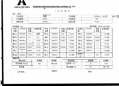
C5191磷青铜
标准:()
特性及适用范围:
磷锡青铜,有高的强度.弹性.耐磨性和抗磁性,在热态和冷态下压力加工性良好,对电火花有较高的抗燃性,可焊接和纤焊,可加工性好,在大气和淡水中耐蚀。
化学成份:
试样尺寸:厚度≥0.15
国内铜合金牌号:(林工①③⑥0①⑦④⑨⑨①⑤)
纯铜:T1 T2 T3
无氧铜:TU0 TU1 TU2
磷脱氧铜:TP1 TP2 TAg0.1
黄铜:H96 H90 H85 H80 H70 H68 H65 H63 H62 H59
镍黄铜:HNi65-5 HNi56-3
铅黄铜:HPb89-2 HPb66-0.5 HPb63-3 HPb63-0.1 HPb62-0.8 HPb62-3 HPb62-2 HPb61-1 HPb60-2 HPb59-3 HPb59-1
加砷黄铜:HAl77-2 HSn70-1 H85A H70A H68A
锡黄铜:HSn90-1 HSn62-1 HSn60-1
铝黄铜:HAl67-2.5 HAl61-4-3-1 HAl60-1-1 HAl59-3-2 HAl66-6-3-2
锰黄铜:HMn62-3-3-7 HMn58-2 HMn57-3-1 HMn55-3-1
铁黄铜:HFe59-1-1 HFe58-1-1
硅黄铜:HSi80-3
锡青铜:QSn1.5-0.2 QSn4-0.3 QSn4-3 QSn4-4-2.5 QSn4-4-4 QSn6.5-0.1 QSn6.5-0.4 QSn7-0.2 QSn8-0.3
铝青铜:QAl5 QAl7 QAl9-2 QAl9-4 QAl10-3-1.5 QAl10-4-4 QAl11-6-6 QAl9-5-1-1 QAl10-5-5铍青铜:QBe2 QBe1.9 QBe1.9-0.1 QBe1.7 QBe0.6-2.5 QBe0.4-1.8 QBe0.3-1.5
硅青铜:QSi3-1 QSi1-3 QSi3.5-3-1.5
锰青铜:QMn1.5 QMn2 QMn5
锆青铜:QZr0.2 QZr0.4
铬青铜:QCr1 QCr0.5 QCr0.5-0.2-0.1 QCr0.6-0.4-0.05
镉青铜:QCd1
镁青铜:QMg0.8
铁青铜:QFe2.5
碲青铜:QFe0.5
白铜:B0.6 B5 B19 B25 B30
铁白铜:BFe5-1.5-0.5 BFe10-1-1 BFe30-1-1
锰白铜:BMn3-12 BMn40-1.5 BMn43-0.5
锌白铜:BZn18-18 BZn18-26 BZn15-20 BZn15-21-1.8 BZn15-24-1.5
铝白铜:BAl3-3 BAl6-1.5
铸造黄铜锭:ZHD68 ZHD62
铸造铝黄铜锭:ZHAlD67-5-2-2 ZHAlD63-6-3-3 ZHAlD62-4-3-3 ZHAlD67-2.5 ZHAlD61-2-2-1
铸造锰黄铜锭:ZHMnD58-2-2 ZHMnD58-2 ZHMnD57-3-1
铸造铅黄铜锭:ZHPbD65-2 ZHPbD59-1 ZHPbD60-2
铸造硅黄铜锭:ZHSiD80-3 ZHSSiD80-3-3
锰铜康铜:6J12 6J13 6J8 6J40
现货供应规格?
铜板厚度0.8 1.0 1.5 2.0 2.5 3.0 4.0 5.0 6.0 8.0 10 12 15 16 20---250mm
铜带厚度0.15 0.2 0.25 0.3 0.4 0.5 0.6 0.8 1.0 1.2 1.5 1.6 2.0mm
铜棒直径∮2.0 3.0 4.0 5.0 6.0 8.0 10 12 16 18 20 25 30 35 38 40--315mm
铜线线径0.1 0.15 0.2 0.3 0.4 0.5 0.6 0.8 1.0 1.2 1.3 1.4 1.5 1.6 1.8 2.0 3.0 4.0mm
以上常规规格均匀现货,特殊尺寸均可按要求订做!
价格说明:市场瞬息万变具体价格请以当日电询为准!
订购说明:
(1)带材:不另外分条,1kg起订;如需另外分条,5kg起订(30kg以上免费分条,30kg以
下另收取30元分条费);
(2)线材:5kg起订,特殊规格订做视具体情况而定;
(3)板材:(薄板),1张起订;(中厚板)可零切订;
(4)棒材:小直径5kg起订,如需几支试样,另视情况而定收取样品费;中大直径1条起订;(5)管材:小直径5kg起订,如需几支试样,另视情况而定收取样品费;中大直径1条起订;本公司以诚信赢得客户,以质量开拓市场!相信每一次的合作,都会让我们彼此走得更近!。