EA实例入门指南..
- 格式:ppt
- 大小:2.19 MB
- 文档页数:55

Agilent G1701EA MSD Productivity ChemStation入门指南Agilent Technologies声明© Agilent Technologies, Inc. 2011未经 Agilent Technologies, Inc. 事先许可和书面同意,不得以任何形式或任何手段(包括电子存储或翻译成外国语言)对本手册的任何部分进行复制,本手册内容受美国法律和国际版权法保护。
手册部件号G1701-97070版本2011 年 7 月,第一版美国印刷Agilent Technologies, Inc.5301 Stevens Creek BoulevardSanta Clara, CA 95051 USA 担保本文档内容按“原样”提供,在将来的版本中如有更改,恕不另行通知。
而且,在适用法律允许的最大范围内,Agilent 不对本手册及其所包含的信息做出任何明示或暗示的担保,其中包括但不限于对适销性和对具体用途适用性的暗示的担保。
Agilent 不对因提供、使用或执行本文档或其中所包含的信息而造成的任何错误或任何意外或附带的损失承担责任。
如果 Agilent 与用户签有单独的书面协议,且协议中涉及本文档所含材料的担保条款与上述条款发生冲突,则该书面协议中的担保条款具有优先法律效力。
技术许可证本文档中描述的硬件和/或软件根据许可证规定提供,只能根据此类许可证的条款进行使用或复制。
有限权利说明如果软件用于履行美国政府主合同或子合同,则按照 DFAR 252.227-7014(1995 年6 月)中的规定,将软件作为“商业计算机软件”进行交付和发放许可,或者按照 FAR 2.101(a) 中的规定,将软件作为“商品”进行交付和发放许可,或者按照FAR 52.227-19(1987 年 6 月)或任何等效代理机构法规或合同条款中的规定,将软件作为“受限计算机软件”进行交付和发放许可。

AI编程初学者指南人工智能(Artificial Intelligence,简称AI)是当今科技领域的热点话题,其影响和应用范围越来越广泛。
对于初学者来说,AI编程可能显得有些困难和复杂。
本文旨在为AI编程初学者提供一份指南,帮助他们快速入门和掌握基本概念。
第一部分:AI基础知识一、什么是人工智能?AI是一种模拟和实现人类智能的技术。
通过使用算法和大量数据,AI系统能够学习、理解、推理和决策,以达到解决问题和执行任务的目的。
二、AI编程的重要性AI编程是实现人工智能系统的关键。
编程是将算法转化为机器可执行的指令,使得AI系统能够运行和实现其智能功能。
三、AI编程的基础工具1. Python编程语言:Python是AI编程最常用的语言之一。
其简洁的语法和丰富的库使得编写AI程序变得更加高效和便捷。
2. TensorFlow:TensorFlow是一个开源的机器学习框架,提供了丰富的API和工具,可以帮助开发者构建和训练各种类型的神经网络模型。
3. Jupyter Notebook:Jupyter Notebook是一个交互式编程环境,可以结合代码、文档和可视化进行开发和调试。
第二部分:入门指南一、学习编程基础在开始AI编程之前,建议初学者先学习基本的编程概念和语法。
可以选择一门简单易学的编程语言,如Python,并通过在线教程、视频课程等方式掌握基础知识。
二、理解机器学习概念机器学习是AI编程的核心技术之一。
初学者需要了解机器学习的基本概念,如监督学习、非监督学习和强化学习,并学习如何构建和训练机器学习模型。
三、使用AI编程框架选择一个适合自己的AI编程框架,如TensorFlow或PyTorch,并学习其基本用法。
可以通过阅读文档、参考示例代码和实践项目来提高自己的编程技能。
四、参与AI社区加入各种AI开发者社区,如GitHub、Stack Overflow、Kaggle等,与其他开发者交流、分享经验和解决问题。
idea全解手册IDEA 是一款强大的集成开发环境,用于支持Java、Kotlin、Groovy 等多种编程语言。
这里提供一份简要的指南,希望对你的使用有所帮助。
1. 安装和启动IDEA:-下载并安装IDEA。
-启动IDEA:安装完成后,启动IDEA 并选择一个合适的配置。
2. 创建和导入项目:-创建新项目:选择"New Project",然后选择项目类型和配置。
-导入现有项目:选择"Open",导入已存在的项目。
3. IDEA 基础操作:-编辑代码:打开一个文件,进行编辑;支持代码智能提示、自动补全等功能。
-导航:使用快捷键导航到类、方法、文件等。
-重构:使用IDEA 提供的重构工具对代码进行重构,如重命名、提取方法等。
-调试:在代码中设置断点,使用调试工具查看变量值、执行流程等。
4. 使用Version Control:-集成Git:IDEA 提供了强大的Git 支持,可以进行代码版本控制。
-查看修改历史:查看代码的修改历史,比较不同版本的代码。
5. 插件和扩展:-安装插件:通过插件市场安装各种插件,扩展IDEA 的功能。
-自定义设置:根据个人喜好,调整编辑器的主题、颜色、字体等设置。
6. 代码检查和优化:-代码分析:使用IDEA 的代码分析工具,检查代码中的问题并进行修复。
-优化建议:根据IDEA 提供的建议,优化代码结构和性能。
7. 整合工具:- Maven 和Gradle:支持Maven 和Gradle 构建工具,方便管理项目依赖。
-数据库工具:整合数据库工具,支持数据库连接、查询等操作。
8. 使用快捷键:-学习常用快捷键:IDEA 提供了丰富的快捷键,提高开发效率。
-自定义快捷键:根据个人习惯,调整和自定义快捷键。
9. 在线资源:-官方文档:查阅IDEA 的官方文档,了解更多功能和用法。
-社区支持:参与IDEA 的用户社区,获取帮助和分享经验。


Q uick S tart G uideFill in for your records: Serial Number:Purchase Date:This guide is intended to assist with initial setup and operation of your Lectrosonics product.For a detailed user manual, down-load the most current version at: /manualsHandheld TransmitterHHa, HHa-941, HHa/E01, HHa/E02,HHa/EO6, HHa/XDigital Hybrid Wireless®US Patent 7,225,13514 October 2019Capsule and Battery InstallationA common threaded mount allows the use of a variety of different capsules fromdifferent manufacturers. Capsules are attached with a right-hand threadA mic capsule isthreaded onto the bodyof the transmitter in thedirection shown.Do not overtighten it.The lower housing opensby rotating it in the directionshown. After the threads aredisengaged, pull the housingdownward until it engages thedetent that holds it open.The threaded interface is a 1.25”opening with 28 threads per inch andthree contact ringsTo remove the windscreenfrom the mic capsule, lineup the blue wrench (thatwas included with yourunit) with the flat notcheson the lower threaded areaof mic capsule.To remove the batteries, pull the eject leveroutward. the battery tips will move outward,making them easier to grasp.To insert batteries, closethe eject lever and insertthe upper contactsfirst (closest to the miccapsule). Polarity ismarked on the label inthe bottom of the batterycompartment.Do not touch the contacts between the mic capsuleand transmitter body. When necessary, the contactscan be cleaned with a cotton swab and alcohol.LECTROSONICS, INC. 2 3Controls and Functions UP/DOWN Buttons for Menu Item SelectionPower ButtonModulation LEDsEnter Menu and Select ItemPrevious ScreenSide ButtonSetup SwitchPowering OnPress and hold the Power Buttonfor several seconds until a countdown on the LCD is completed. The countdown from 1 through 3 will appear on theLCD, followed by a display of the model, firmware version, frequency block and compatibility mode.When you release the button, the unit will be operational with the RF output turned on and the Main Window displayed.The Main WindowNOTE: If the Power Button i s released before the countdown iscompleted, the unit will boot up in the “standby” mode with the RF output turned off.Powering OffPress and hold the Power Button for several seconds and observe the count-down on the LCD. The countdown on the LCD will progress from 3 to 1 and the power will then be turned off. This can be done from any menu or screen.NOTE: If the Power Button is released before the countdown iscompleted, the unitwill remain turned on and the LCD willreturn to the same screen or menu that was displayed previously.Standby ModeA brief push of the Power Button turns the unit on and places it into a “standby” mode (not transmitting). This allows the transmitter to be set up without the risk of creating interference for other wireless systems that are operating in the vicinity.A notice will appear briefly confirming that the RF output of the transmitter is turned off, followed by the Main Window. A symbol will blink as a reminder that the RF output is turned off.SymbolPower MenuWith the unit turned on, a brief push of the Power Button will reveal a menu al-lowing you to choose between Resume , Pwr Off, Rf On?, and Backlit . Use the UP/DOWN buttons to select one of these menu items, then press the MENU/SEL button to confirm this action.Continued on pg 4.IR Sync Port• Resume: Continue operating in the same condition as before.• Pwr Off?: Turns off the transmitter.• Rf On?: Begin transmitting the RF signal.• Backlit: The LCD backlight is set to come on when any button onthe control panel is pressed, thenstay on for either 30 seconds or 5minutes, or to stay on all the time.. The unit can also be turned off from any menu or screen on the LCD by holding the power button in for the duration of the countdown.Battery ConditionAn icon on the Main Window indicates the remaining power of the transmitter batteries. This battery gauge is most accurate with the typical voltage drop across the life of alkaline and dry cell lithium batteries.Rechargeable batteries give little or no warning when nearing depletion. If you use rechargeable batteries in the HHa, we recommend trying fully charged batteries first, noting the length of time that the batteries will run the unit, andin the future using somewhat less than that time to determine when the battery needs to be replaced. The Venue and other receivers from Lectrosonics offer a timer function to assist in this process. Menus and Screens The Main Window displays the following information:Hex Code forOperating Icon indicates whether RFoutput is turned on or off in MHzside button1) Press the MENU/SEL button toenter the setup menu. Use the UP/DOWN buttons to highlight themenu item.2) Press the MENU/SEL button to en-ter the setup screen for that item.Use the UP/DOWN buttons toselect the desired value or mode.3) Press the MENU/SEL button tosave this setting and return to theprevious screen.4) Press the BACK button to return tothe Main Window.GainThis setting is very important since it will determine the audio signal to noise ratio and dynamic range that the wireless system will deliver. Gain must be set according to the individual voice, the mic capsule in use and the handling tech-nique of the user. LEDs in the control panel facilitate accurate gain adjustment.IMPORTANT: See the sectionAbout Setting Audio Gain onpage 6 for details.Freq.is normally determinedusing the scanningfunction in the receiveror with coordinationsoftware. The frequency is shown on the transmitter LCD display in MHz and with a hexadecimal code that is used on most Lectrosonics receivers.LECTROSONICS, INC.45ProgSwThe Programmable Switch on the housing can be set to Talkback, Power, Cough or a Mute function, or be bypassed (none).RolloffA sharp low frequencyrolloff filter protectsagainst breath popsand can be used toadjust the frequencyresponse to suitpersonal preferences. The slope istypically 36 dB/octave and varies slightly as the turnover point is selected.CompatThe HHa can be used with earlier Lec-trosonics wireless and IFB systems and systems from other manufacturers by selecting the correct Compatibility Mode . The receiver must be set to the same mode .The available modes are as follows:• Nu Hybrid: Digital Hybrid receivers • Mode 3: (other brand contact the factory)• IFB Mode: Lectrosonics IFB receiv-ersNOTE: If your Lectrosonics receiver does not have Nu Hybrid mode, set thereceiver to Euro Digital Hybrid Wireless® (EU Dig. Hybrid).StepSizThe frequency can be adjusted in 100 kHz or 25 kHz steps to match the receiver. 100 kHz is the standard increment forLectrosonics wireless systems, but 25 kHz increments may be needed for use with systems from other manufacturers or when frequency coordination requires it.The Hex Code on the Main Screen will be smaller in the 25 kHz mode and a fraction will appear next to the characters if a frequency in between even 100 kHz steps is selected.modeTxPowerOutput power can be set to 100 mW to extend operating range (whichcan also suppress noise and dropouts to some extent) or set to50 mW to extend the operating life of the batteries. US: Selectable 25 or 100 mW 941: Selectable 50 or 100 mW E01: Selectable 25 or 50 mW E02: 10 mWE06: Selectable 50 or 100 mW EIRPX:Selectable 50 or 100 mWPhaseThe phase (polarity) of the audio can be inverted to match other microphone capsules as needed.LECTROSONICS, INC.6Rf On?The transmitter output can be switched on or off with this menu item. This isuseful, for example, when the transmitter is in the “standby” mode during setup, allowing it to be turned on for normal operation without having to cycle thepower.This menu item can also be used to change the transmitter to the “standby” mode with the RF output turned off for additional setup.DefaultThe default setting simple returns the transmitter back to the factory settings and any of the menu items can be read-justed from that default point.Input Gain AdjustmentThe two bicolor Modulation LEDs (lo-cated at the bottom of the control panel) provide a visual indication of the audio signal level entering the transmitter.The modulation LEDs are oriented and labeled to be read when holding the mic capsule in front of your mouth.The gain should be set so that the -20 LED just turns red on the loudestpeak.The LEDs will glow either red or green to indicate modulation levels as shown inthe following table.It is best to go through the following procedure with the transmitter in the “standby” mode so that no audio will enter the sound system, which could cause feedback.1) With fresh batteries in the trans-mitter, power the unit on into“standby” (no transmission) mode.2) Press the MENU/SEL button onceto enter the setup menu. Use the UP/DOWN buttons to select Gain . Press the MENU/SEL button again to enter the setup screen.3) Hold the microphone the way it willbe used in actual operation.4) Speak or sing at the same voicelevel that will actually be used dur-ing the program, while observing the modulation LEDs. Use the UP/DOWN buttons to adjust the gain until the –20 dB LED starts to flicker red and the –10 dB glows green.5) Once the audio gain has been set,the signal can be sent through the sound system for overall level adjustments, monitor settings, etc. To do this, the unit must be set to transmit (see Powering On and Off , and the Standby Mode on page 3).NOTE: Full modulation isachieved when the -20 LED first turns red. 30 dB of clean limiting is available above this point.Programmable Switch FunctionsA special button (the Side Button)on the outside of the housing can be configured to provide several different functions, or to be inoperative.The ProgSw on the control panel opens a setup screen to select the function of the Side Button .Side Button Functions:• TalkBack• Power• Cough• Push To Talk• Mute• (none)The ProgSw menu provides a scrollable list of the available functions. Us the UP/ DOWN arrows to highlight the desired function and press BACK or MENU/SEL to select it and return to the main menu.Press theProgrammable Switchor select ProgSw onthe main menu.Side ButtonSetup SwitchTalkback is a “push to talk” function that is active only while the button is pressed. The talkback function provides a com-munication channel when used with a receiver equipped with this function, such as a Venue Wideband receiver with firmware Ver. 5.2 or higher. When pressed and held in, the side buttonre-directs the audio output to a differ-ent audio channel on the receiver. As soon as the switch is released, audio is returned to the program channel.NOTE: The Talkback functionis only available in the DigitalHybrid compatibility mode. Anerror message will appear ifTalkback is selected while inanother mode.Power turns the power on and off.Hold the button in until the countdown sequence from 3 to 1 is completed. The power will then be turned off.Cough is a momentary mute switch. Au-dio is muted while the button is held in. Push to Talk is a momentary talk switch. Audio is transmitted while the button is held in (opposite of cough).Mute is a “push on/push” off function that toggles on and off each time the Side Button is pressed. The mute func-tion defeats the audio in the transmitter, so it works in all compatibility modes and with all receivers.(none) disables the switch.For detailed information on setting up the Talkback function and the Venue receiver, refer to the Installa-tion Guide for the Venue Wideband Receiver.Main Window Displays for Mute and Talkback FunctionsThe function of the SideButton is displayed inthe LCD Main Window.When the Side Buttonis pressed, the functionwill be active and theLCD will display anindication.7LIMITED ONE YEAR WARRANTYThe equipment is warranted for one year from date of purchase against defects in materials or workmanship provided it was purchased from an authorized dealer. This warranty does not cover equipment which has been abused or damaged by careless handling or shipping. This warranty does not apply to used or demonstrator equipment.Should any defect develop, Lectrosonics, Inc. will, at our option, repair or replace any defective parts without charge for either parts or labor. If Lectrosonics, Inc. cannot correct the defect in your equipment, it will be replaced at no charge with a similar new item. Lectrosonics, Inc. will pay for the cost of returning your equipment to you.This warranty applies only to items returned to Lectrosonics, Inc. or an authorized dealer, shipping costs prepaid, within one year from the date of purchase.This Limited Warranty is governed by the laws of the State of New Mexico. It states the entire liablility of Lectrosonics Inc. and the entire remedy of the purchaser for any breach of warranty as outlined above. NEITHER LECTROSONICS, INC. NOR ANYONE INVOLVED IN THE PRODUCTION OR DELIVERY OF THE EQUIPMENT SHALL BE LIABLE FOR ANY INDIRECT, SPECIAL, PUNITIVE, CONSEQUENTIAL, OR INCIDENTAL DAMAGES ARISING OUT OF THE USE OR INABILITY TO USE THIS EQUIPMENT EVEN IF LECTROSONICS, INC. HAS BEEN ADVISED OF THE POSSIBILITY OF SUCH DAMAGES. IN NO EVENT SHALL THE LIABILITY OF LECTROSONICS, INC. EXCEED THE PURCHASE PRICE OF ANY DEFECTIVE EQUIPMENT.This warranty gives you specific legal rights. You may have additional legal rights which vary from state to state.®。
Enterprise Architect 7.0入门教程真挚而纯洁的爱情,一定渗有对心爱的人的劳动和职业的尊重。
——孔仁峰目录1简介 32创建工程 53一些基本的通用设置 73.1设置默认代码环境 73.2设置默认数据库 84 Class模型 94.1创建“Class”模型 94.2为模型中创建的“Class”对象使用别名 105代码的生成 125.1把整个包的设计类生成C#格式代码 125.2单个自动生成C#代码 136设计模型与生成的代码同步 147数据库模型,需求模型,组件,部署 147.1 建立数据表 147.2建立数据表 158文档的生成 178.1 Text文档的生成 178.2 Html文档的生成 189将包导入成XML形式 1910画图的线的弯曲,自动布局,改变线的连接点的方法 1911图、注释、字体的基本操作 2011.1活动图的绘制 2011.2时序图的绘制 2211.3如何添加注释 2411.4设置图中的字体样式 2411.5将一个图的元素重新复制一份新的到其它图 251简介生命周期软件设计方案——Enterprise Architect是以目标为导向的软件系统。
它覆盖了系统开发的整个周期,除了开发类模型之外,还包括事务进程分析,使用案例需求,动态模型,组件和布局,系统管理,非功能需求,用户界面设计,测试和维护等。
为整个团队提供高级的UML 2.0建模工具。
EA为用户提供一个高性能、直观的工作界面,联合UML 2.0最新规范,为桌面电脑工作人员、开发和应用团队打造先进的软件建模方案。
该产品不仅特性丰富,而且性价比极高,可以用来配备您的整个工作团队,包括分析人员、测试人员、项目经理、品质控制和部署人员等。
丰富系统设计Enterprise Architect是一个完全的UML分析和设计工具,它能完成从需求收集经步骤分析、模型设计到测试和维护的整个软件开发过程。
它基于多用户Windows平台的图形工具可以帮助您设计健全可维护的软件。


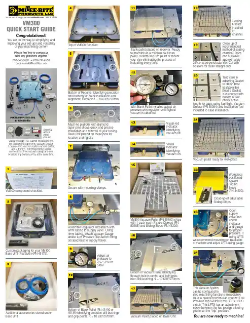
VM300Quick Start GuideCongratulations!!You are on the way to simplifying and improving your set-ups and versatilityof your machining center!Please feel free to contact us with any questions anytime 800-543-3580 • 603-539-4538***********************340 Rte. 16B • Ctr. Ossipee, NH 03814 • MADE IN THE USAVM300 component checklist.1Custom packaging for your VM300 Base Unit (Receiver) (PN 45175).2Additional accessories stored under Base Unit.3Secure with mounting clamps.7Assemble Regulator and attach with 6mm tubing to Supply Valve. Using 4mm tubing, attach Vacuum Gauge and/or Low Pressure Trip Switch fitting (located next to Supply Valve).8Adjust air pressure to 70-75 PSI or 5 bar.9With Blank Pallet installed adjust air pressure with regulator until highest vacuum is obtained.12Visual indicator identifying vacuum on.14VM300 Vacuum Pallet (PN 45150) ships with 1 pack each: Fixture Clamps (PN 50206) and Sliding Stops (PN 44200).15Vacuum pallet ready for workpiece.21Workpiece positioned against Sliding Stops(PN 44200).Close-up of adjustable Sliding Stops.22Vacuum Pallet placed on Base Unit.17Sealing Gasket installed inchannel.18Close up ofrecommended method of sealing chamber. Place end of Gasket approximately25% into perpendicular slot. Cut with scissors for clean straight end.19Top of VM300 Receiver.413Visual red indicator identifying vacuum off.Take care inadjusting Gasket to obtain best seal possible. Ensure Gasket is in contact with bottom of slot, check entirelength for gaps using flashlight. Vacuum Grease (PN 45094) and Installation Tool included to ease installation.20Recently added items include:Vacuum Gauge (12), Gasket Installation Tool, Set of Diamond Taper Pins, Vacuum Grease, 3 Carbide End Mills for custom vacuum plates,and a 4mm “Y” Connector which allows connections of the Vacuum Gauge and Low Pressure Trip Switch (LPTS) at the same time.Bottom of Receiver identifying precision drill bushing for quick installation and alignment. Centerline = 10.630"/270mm.5Machine platform with diamond taper pins allows quick and precise installation and removal of your tooling. Base Unit placed on these pins for location and rigidity.6Part Number 45175 andall accessories10Bottom of Blank Pallet (PN 45130 or 45135) identifying precision drill bushingsand grip points. CL = 10.630"/270mm.Blank pallet placed on receiver. Ready to machine as a mechanical fixture pallet, custom vacuum pallet or mount your vise eliminating the process of indicating every time.11Bottom of Vacuum Pallet identifying through hole in center and both prec-ision drill bushing. CL = 10.630"/270mm.16Open supply valve and check indicator and gauge for proper pressure. If using LPTSwe recommend mounting on backside of machine and adjust LPTS using gauge.23This Vacuum Systemcan be configured tostop machining functions immediately. Have a qualified technician connect Low Pressure Trip Switch to the FEED HOLD circuit. This LPTS has an adjustment screw between the two prongs allowing you to set the “trip” pressure.24T ripScrewY ou are now ready to machine!。
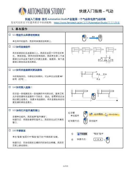
快速入门指南- 使用Automation Studio™创建第一个气动和电控气动回路您还可以在以下位置查看多个培训视频:https://www.famictech.ca/zh/支持/Automation-Studio/学习与探索“缩放”组中1) “缩放”组中点击组件2.创建第一个气动回路☐ 2.1插入气动组件第一个回路所需的所有组件都包含在主气动库中。
只需单击它即可显示组件,然后将库中的以下组件(第1.1节)拖放到图面上:•气动压力源• 3 x 排放•双作用缸•3/2-常开阀•5/2-换向阀☐ 2.2现在将所有元素连接在一起请参阅上面的基本操作提示(第1节)以完成气动回路的连接。
更改连接路径连接组件3.仿真☐ 3.1开始仿真,令你设计的回路活动起来!现在所有组件都已连接,您可以开始仿真。
点击“仿真”选项卡中的控制组下的“正常仿真”图标以启动仿真。
1) 点击“仿真”选项卡2) 点击“正常仿真”图标☐ 3.2激活命令项在仿真中,当鼠标悬停在组件上时,如果光标变为手形图标,则可单击以激活该组件命令项。
☐ 3.3截面动画在仿真中,您可以查看以红色显示的任何组件的横截面动画。
只需右键单击该组件,然后选择“动画模块”。
要执行此操作,请右键单击该换使用者移动换向阀以重合作用缸杆末端与换向阀机械传感器☐ 4.8更改换向阀上的命令类型1)点击按钮;2)点击“删除”;3)双击复位弹簧打开命令选择窗口;4)选择“外部气动先导操纵”命令;5)使用箭头将螺线管“?”的位置移动到您喜欢的位置;6)重复步骤3至5,用外部气动先导操纵更换左边螺线管。
0.6 mm☐ 4.11添加测量仪器添加测量仪器可以让您在仿真过程中获取压力和流量读数。
1)从库中添加两个压力表,并将其连接到双作用作用缸(1)和(2)的两个端口。
2)从库中添加流量计,并将其放置在回路(3)的两个主要换向阀之间。
**直接从库中添加组件时,可以将其直接放到一管路上,它将自动插入到回路中。

w w w.a u t o m a t i o n d i r e c t .c o m /C -m o r e C -m o r e Operator Touch PanelseCR-29Company Information Systems OverviewProgrammable ControllersField I/O Software C-more & other HMIDrives Soft StartersMotors &Gearbox Steppers/ServosMotor Controls Proximity SensorsPhoto Sensors Limit Switches Encoders Current Sensors Pressure SensorsTemperature Sensors Pushbuttons/LightsProcess Relays/TimersComm.Terminal Blocks & Wiring PowerCircuit Protection EnclosuresTools Pneumatics Safety Appendix Product Index Part #IndexVolume 14C-more Operator Panels OverviewFor new applications choose EA9 series C-more panels, part numbers EA9-TxCL(-R).Volume 14<---><---><---><--->C-more Selection Guide & SpecificationsFor new applications choose EA9 series C-more panels, part numbers EA9-TxCL(-R).1-800-633-0405 eCR-30C-m o r e Operator T ouch PanelsCompany Information Systems Overview Programmable ControllersField I/O SoftwareC-more & other HMIDrives Soft Starters Motors &Gearbox Steppers/Servos Motor Controls Proximity Sensors Photo Sensors Limit Switches Encoders Current Sensors Pressure Sensors Temperature Sensors Pushbuttons/Lights Process Relays/Timers Comm.Terminal Blocks & Wiring PowerCircuit Protection EnclosuresToolsPneumatics SafetyAppendix Product IndexPart #IndexPart No. EA7-T12C<--->PLC DriversSerialCompany InformationSystems OverviewProgrammable ControllersField I/O SoftwareC-more & other HMIDrivesSoft StartersMotors & GearboxSteppers/ ServosMotor ControlsProximity SensorsPhoto SensorsLimit SwitchesEncodersCurrent SensorsPressure SensorsTemperature SensorsPushbuttons/ LightsProcessRelays/ TimersComm.Terminal Blocks & WiringPowerCircuit ProtectionEnclosuresToolsPneumaticsSafetyAppendixProduct IndexPart # Index1-800-633-0405eCR-42C -m o r e Operator T ouch PanelsVolume 14C-more Communication Protocols & CablesNOTE: EZTouch serial PLC communication cables are compatible with C-more touch panels.EA-2CBLEA-2CBL-1For new applications choose EA9 series C-more panels, part numbers EA9-TxCL(-R).w w w.a u t o m a t i o n d i r e c t .c o m /C -m o r eC -m o r e Operator Touch PanelseCR-43Company Information Systems Overview Programmable ControllersField I/O Software C-more & other HMIDrives Soft Starters Motors &Gearbox Steppers/Servos Motor Controls Proximity Sensors Photo Sensors Limit Switches EncodersCurrent Sensors Pressure Sensors Temperature Sensors Pushbuttons/Lights Process Relays/Timers Comm.Terminal Blocks & Wiring PowerCircuit Protection Enclosures Tools Pneumatics Safety Appendix Product Index Part #IndexVolume 14The Ethernet Configuration Kit includes a five-port 10/100 Base-T Ethernet switch,four straight-through cables, and one crossover cable. (The cables are at least five feet in length.) The kit provides a great convenience for configuring systems,demonstration systems or basic control proj-ects using Ethernet.a deviceMessage is sent out only from the port connected to destination devicePart No. SE-SW5UStride™Ethernet SwitchEthernet Configuration KitUSB Programming CablePart No. USB-CBL-AB15C-more Computer Programming Connections<---><--->Other lengths available see USB-CBL-AB3, USB-CBL-AB6,USB-CBL-AB10 on page 9-27Part No. RT -CNFGKIT<--->For new applications choose EA9 series C-more panels, part numbers EA9-TxCL(-R).1-800-633-0405eCR-44C -m o r e Operator T ouch PanelsVolume 14Providing Power to the Touch Panel• Connect a dedicated 24 VDC switching power supply rated for a minimum of 1.5 Amps to the DC connector on the rear of the C-more touch panel. Connect the ground terminal to a proper equipment ground.• or, install a C-more AC Power Adapter (EA-AC) to the rear of the touch panel and connect an AC voltage source of 100-240 VAC,50/60Hertz, to its AC connector.• then, turn on the power source and check the LED status indicators on the rear of the C-more touch panel for proper operation.W o minimize the riskof potential you should follow all applicable and national codes that regulate the installation and operation of your equipment. These codes vary from area to area and it is your responsibility to determine which codes should be followed, and to verify that the equipment, installation, and operation are in compliance with the latest revision of these codes.Equipment damage or serious injury topersonnel can result from the failure to follow all applicable codes and standards.We do not guarantee the products described in this publication are suitable for your particular application, nor do we assume any responsibility for your product design, installation, or operation.If you have any questions concerning the installation or operation of this equipment,or if you need additional information,please call us at 1-800-633-0405 or 770-844-4200.This publication is based on information that was available at the time it was printed.At ®we constantly strive to improve our products and services,so we reserve the right to make changes to the products and/or publications at any time without notice and without obligation.This publication may also discuss features that may not be available in certain revisions of the product.C-more Power Connection WiringFor new applications choose EA9 series C-more panels, part numbers EA9-TxCL(-R).w w w.a u t o m a t i o n d i r e c t .c o m /CCompany Information Systems Overview Programmable ControllersField I/O Software C-more & other HMI Drives Soft Starters Motors &Gearbox Steppers/Servos Motor Controls Proximity SensorsPhoto Sensors Limit Switches Encoders Current Sensors Pressure Sensors Temperature Sensors Pushbuttons/Lights Process Relays/Timers Comm.Terminal Blocks & Wiring PowerCircuit Protection Enclosures ToolsPneumatics Safety Appendix Product Index Part #IndexAccessoriesThe C -m o r e touch panels can be enhanced with the accessories below:NOTE: Refer to the individual product data sheets that are included with the accessories E XPANSION A SSEMBL EA-EXP-OPTM EMORY C ARD EA-CF-CARDAC/DC P OWER A DAPTEREA-ACC -m o r e T OUCH P ANELNOTE: CompactFlash card designations – CF Slot #1is at the top of the panel CF Slot #2 is the Interface Module, p/n EA-CF-IF.CF card plugs into slot #1at top of panel.left slot for future.C-more USB P EN D SDCZ4-2048-A11-800-633-0405eCR-46C -m o r e Operator T ouch PanelsVolume 14C-more AccessoriesAC/DC Power AdapterThe AC/DC Power Adapter provides dedicated DC power to the panel if using 110 VAC as a power source. The AC/DC Power Adapter provides some features that a normal DC power supply cannot provide. The adapter provides a power loss signal to the touch panel that can be used to track power outages. Thissignal also allows the touch panel by way of a timed sequence to stop writing data to CompactFlash memory devices providing a controlled shutdown for increased data logging reliability.Part No. EA-AC Overall Panel Depth w/ EA-AC InstalledDimensionsAC/DC Power Adapter SpecificationsNOTE: The AC/DC Power Adapter is not recommended for use with the EA7-T15C touch panel when operating temperatures are expected to exceed 40 °C [104 °F].NOTE: data being logged to CompactFlash during power must 6.18E or higher for proper operation.<--->For new applications choose EA9 series C-more panels, part numbers EA9-TxCL(-R).Company Information Systems Overview Programmable ControllersField I/O Software C-more & other HMIDrives Soft Starters Motors &Gearbox Steppers/Servos Motor Controls Proximity Sensors Photo SensorsLimit Switches Encoders Current SensorsPressure Sensors Temperature Sensors Pushbuttons/Lights Process Relays/TimersComm.Terminal Blocks & Wiring Power Circuit ProtectionEnclosures Tools Pneumatics SafetyAppendix Product Index Part #Index<---><--->Part No. EA-EXP-OPTPart No. EA-CF-IFOverall Panel Depth w/ EA-EXP-OPT1-800-633-0405eCR-48C -m o r e Operator T ouch PanelsVolume 14<--->EA-CF-CARDUSB Pen DriveC-more AccessoriesPart No.SDCZ4-2048-A10<--->The SanDisk Cruzer Edge is a small 2GB USB Flash Drive (UFD) that connects to a USB port. Users can easily store their logging data, project data, key documents and images on a Cruzer Edge and transfer them to another computer with a USB port.• Dimensions: (W x L x D) 0.80” x 2.30” x 0.40 “Specifications/Features:• CompactFlash™ Compatibility • W/E Endurance 100,000 cycles • Data transfer rate: 16 MB/second• Operating T emp: -13 to 185°F ( -25 to 85°C )• Operating Humidity 85% max, non-condensing • Storage T emp: -13 to 194 °F ( -25 to 90°C )• Storage Humidity 95% max, non-condensingFor new applications choose EA9 series C-more panels, part numbers EA9-TxCL(-R).w w w.a u t o m a t i o n d i r e c t .c o m /C -m o r e C -m o r e Operator Touch PanelseCR-49Company Information Systems Overview Programmable ControllersField I/O Software C-more & other HMI Drives Soft StartersMotors &Gearbox Steppers/Servos Motor Controls Proximity Sensors Photo Sensors Limit SwitchesEncoders Current SensorsPressure Sensors Temperature Sensors Pushbuttons/Lights Process Relays/TimersComm.Terminal Blocks & WiringPower Circuit ProtectionEnclosures ToolsPneumatics Safety Appendix Product Index Part #IndexVolume 14C-moreAccessories6” Adapter PlateThe adapter plate simplifies the retrofit of a new C -m o r e 6” touch panel into an existing cabinet cutout for an EZT ouch (units sold by AutomationDirect) 6” wide bezel touch panel, such as our part number EZ-S6C-K, EZ-S6C-F , EZ-S6M-R or EZ-S6M-F .A NEMA 4/4X gasket is included. Please note that all sizes of the C -m o r e touch panels have the same cutout as similarly sized EZTouch thin bezel (slim) touch panels, allowing quick replace-ment.<--->Part No. EA-6-ADPTRMounting DetailsFor new applications choose EA9 series C-more panels, part numbers EA9-TxCL(-R).1-800-633-0405eCR-50C -m o r e Operator T ouch PanelsVolume 14C-more AccessoriesD-SUB 15-pin to Terminal Block AdapterThe EA-COMCON-3 adapter plugs into the 15-pin serial port on the rear of the panel to allow wire terminal connections for an RS-422/RS-485/DH-485 PLC communication cable. UL Recognized. For use with all -m o r e EA7 series panels, C -m o r e EA9-T6CL and C -m o r e Micro-Graphic 4” and 6” panels.<---><--->EA-ADPTR-4EA-COMCON-30.412[10.5]0.751Units: inches [mm]For new applications choose EA9 series C-more panels, part numbers EA9-TxCL(-R).Company Information Systems Overview Programmable ControllersField I/O Software C-more & other HMI DrivesSoft Starters Motors &Gearbox Steppers/Servos Motor Controls Proximity Sensors Photo Sensors Limit Switches EncodersCurrent SensorsPressure Sensors Temperature Sensors Pushbuttons/Lights Process Relays/Timers Comm.Terminal Blocks & Wiring Power Circuit ProtectionEnclosures Tools Pneumatics Safety Appendix Product Index Part #IndexInstallationNOTE: The Protective Cover ships with a thin protective sheet on the face of the cover that needs to be carefully removed. If your panel is not clear, the protective sheet may not have been removed.1-800-633-0405eCR-52C -m o r e Operator T ouch PanelsVolume 14EA-8-BULB, EA-8-BULB2,EA-10-BULB, EA-10-BULB2, EA-12-BULB, EA-12-BULB2,EA-15-BULB, & EA-15-BULB2see tablePanels with serial numbers newer than November 2013 do not have user replaceable backlights. For earlier panels, thecorrect replacement bulb part number is provided in the adjacent table. No 6” panels have user replaceable backlights. Older 8”, 10” and 15”touch panels use two bulbs per panel and the 12” touch panels use one bulb per panel. The bulbs are packaged two per box for the 8”, 10”and 15” touch panels and one per box for the 12” touch panels.C-more Replacement PartsYY: Year (05–99 --- e.g. 05 = 2005)M: Month (1–9, X, Y , Z --- e.g. X = Oct.)DD: Day (1–31)F: Manufacturing Site (0–9, A–Z)NNN: Sequence number for the date listed (000–999)Serial Number =[Part Number]+[YYMDDFNNN ]For new applications choose EA9 series C-more panels, part numbers EA9-TxCL(-R).Company Information Systems Overview Programmable ControllersField I/O Software C-more & other HMI Drives Soft Starters Motors &Gearbox Steppers/Servos Motor Controls Proximity Sensors Photo Sensors Limit Switches Encoders Current Sensors Pressure Sensors Temperature Sensors Pushbuttons/Lights Process Relays/TimersComm.Terminal Blocks & Wiring Power Circuit Protection Enclosures Tools Pneumatics Safety Appendix Product Index Part #IndexDC Power Connector Part No. EA-DC-CONPart No. EA-AC-CONEA-12-GSK and EA-15-GSKand EA-15-BEZELPart No. EA-6-ADPTR-GSKReplacement 5-terminal DC power connector for C -m o r e touch panels.Replacement 3-terminal AC connector for C -m o r e touch panel Power Adapters.Replacement NEMA 4/4X touch panel gaskets for C -m o r e 6”, 8”, 10”, 12” and 15” touch panels.NEMA 4/4X bezel, customer replaceable,for C -m o r e 8”, 10”, 12” and 15” touchpanels. Gasket not included.6-inch replacement NEMA 4/4X gasket for the C -m o r e touch panel adapter plate.MAINTENANCE HTTP Backup Battery (supplied with new panels) Part No. D2-BAT -1Part No. EA-BRK-1Part No. EA-BRK-2panel mounting clips for touch panels. Package of 2 clips with 4 screws.Spare panel mounting clips for the 8-inch through 15-inch C -m o r e touch。
SIMATIC S7-300新手入门指南订货号 6ZB5310-0NC27-0BA0版本 04/2007A5E01094751-01目录1欢迎 . . . . . . . . . . . . . . . . . . . . . . . . . . . . . .22准备 PC. . . . . . . . . . . . . . . . . . . . . . . . . . . . .63安装硬件并为其接线. . . . . . . . . . . . . . . . . . . . . . . 103.1需要哪些组件?. . . . . . . . . . . . . . . . . . . . . . . . . 113.2安装组件 . . . . . . . . . . . . . . . . . . . . . . . . . . . 123.3为组件接线. . . . . . . . . . . . . . . . . . . . . . . . . . . 143.4调试硬件 . . . . . . . . . . . . . . . . . . . . . . . . . . . 214在 STEP 7 Lite 中组态控制. . . . . . . . . . . . . . . . . . . . 264.1什么是 STEP 7 Lite 项目?. . . . . . . . . . . . . . . . . . . . 274.2打开 STEP 7 Lite 项目. . . . . . . . . . . . . . . . . . . . . . 284.3复制 STEP 7 Lite 中的模块组态 . . . . . . . . . . . . . . . . . . 294.4在 PC 和 CPU 312C 之间建立在线连接. . . . . . . . . . . . . . . . 354.5下载并检查 CPU 312C 的模块组态. . . . . . . . . . . . . . . . . . 365打开 PC 上的程序. . . . . . . . . . . . . . . . . . . . . . . . 405.1什么是程序?. . . . . . . . . . . . . . . . . . . . . . . . . . 415.2打开程序 . . . . . . . . . . . . . . . . . . . . . . . . . . . 426执行测试运行. . . . . . . . . . . . . . . . . . . . . . . . . . 446.1将项目下载到 CPU 312C. . . . . . . . . . . . . . . . . . . . . . 456.2开始测试运行. . . . . . . . . . . . . . . . . . . . . . . . . . 467祝贺您 . . . . . . . . . . . . . . . . . . . . . . . . . . . . 508其它信息 . . . . . . . . . . . . . . . . . . . . . . . . . . . 528.1诊断 / 校正错误 . . . . . . . . . . . . . . . . . . . . . . . . 538.2其它文档 . . . . . . . . . . . . . . . . . . . . . . . . . . . 548.3SIMATIC 技术支持. . . . . . . . . . . . . . . . . . . . . . . . 5611欢迎23欢迎阅读《S7-300 新手入门指南》。