M270HGE-L10 ver 3.0规格书
- 格式:pdf
- 大小:582.66 KB
- 文档页数:25

Dell™ OptiPlex™ 170L 使用者指南註、注意事項和警示縮寫和簡寫用語若要獲得縮寫和簡寫用語的完整清單,請參閱詞彙表。
如果您購買的是 Dell™ n Series 電腦,則本文件中關於 Microsoft ® Windows ® 作業系統的所有參考均不適用。
電腦的說明文件尋找有關您電腦的資訊 規格 清潔您的電腦進階功能LegacySelect 技術控制 管理功能 安全保護 密碼保護 系統設定程式 啟動至 USB 裝置 電源按鈕 電源管理 超執行緒小型桌上型電腦關於您的電腦前視圖 後視圖 主機內部 主機板元件連接與卸下電腦腳架新增和卸下零件開始之前 打開機箱蓋 電池 插卡 底架喇叭 磁碟機 I/O 面板 記憶體 電源供應器 處理器 主機板 裝回機箱蓋迷你直立型電腦關於您的電腦前視圖 後視圖 主機內部 主機板元件新增和卸下零件開始之前 卸下機箱蓋 電池 插卡 底架喇叭 控制面板 磁碟機 I/O 面板 記憶體 電源供應器 處理器 主機板 裝回機箱蓋電腦和軟體問題進階故障排除 解決問題 獲得幫助其他資訊Microsoft ® Windows ® XP 功能 詞彙表 保固註:「註」表示可以幫助您更有效地使用電腦的重要資訊。
注意事項:「注意事項」表示有可能會損壞硬體或導致資料遺失,並告訴您如何避免此類問題。
警示:「警示」表示可能會導致財產損失、人身受傷甚至死亡。
Drivers and Utilities CD (ResourceCD)、作業系統媒體以及《快速參考指南》都是可選的,它們可能並非隨附於所有電腦。
本文件中的資訊如有更改,恕不另行通知。
©2004D e l l I n c.。
版權所有,翻印必究。
未經 Dell Inc. 的書面許可,不得以任何形式進行複製。
本文中使用的商標:D e l l、D E L L徽標、O p t i P l e x、I n s p i r o n、D i m e n s i o n、L a t i t u d e、D e l l P r e c i s i o n、D e l l N e t、T r a v e l L i t e、P o w e r V a u l t、P o w e r A p p、A x i m和 Dell OpenManage是 Dell Inc. 的商標﹔I n t e l, P e n t i u m 和 C e l e r o n是 Intel Corporation 的註冊商標﹔M i c r o s o f t、M S-D O S和 W i n d o w s是 Microsoft Corporation 的註冊商標﹔IBM和 O S/2是 International Business Machines Corporation 的註冊商標﹔NetWare和 N o v e l l是 Novell, Inc. 的註冊商標。
PP41型壁厚控制器使用说明书贝加莱工业自动化(上海)有限公司目录系统特性简介 (3)1系统特性介绍 (3)2控制系统各部件介绍 (4)2.1控制操作面板 (4)2.1.1 面板 42.1.2 接口 52.1.3 性能 62.1.4 安装 62.2功能按键及指示灯 (7)2.3控制器及接线 (9)2.3.1AI351 (9)2.3.2 Am351 (10)2.3.3 PP41自带输入 (10)2.3.4 PP41自带输出 (11)3画面操作说明 (12)3.1登陆画面 (12)3.2连续式型胚曲线设定画面 (12)3.2.1 操作按钮 (12)3.2.2 输入参数 (13)3.2.3 输出参数 (14)3.2.4 插入与删除设定数值点 (14)3.2.5 微调设定数值点间的曲线单元 (15)3.3储料式型胚曲线设定画面 (17)3.3.1 操作按钮 (17)3.3.2 输入参数 (18)3.3.3 输出参数 (19)3.4曲线跟踪画面 (19)3.5标记画面 (20)3.6存储画面 (20)3.7文件改名画面 (21)3.8参数存储画面 (21)3.9文件调出画面 (22)3.10监控画面 (22)3.11数据1(曲线点)画面 (22)3.12数据2画面 (23)3.13初始设定画面 (23)3.13.1 输入参数 (23)3.13.2 模式转换 (24)3.14型芯设定画面 (24)3.14.1 输入参数 (24)3.14.2 输出参数 (25)3.14.3 手动调校 (25)3.14.4 自动调校 (25)3.14.5 调校提示: (25)3.15储料设定画面 (26)3.15.1 输出参数 (26)3.15.2 手动调校 (26)3.16增益设定画面 (26)3.16.1 按钮 273.16.2 输入参数 (27)3.16.3 输出参数 (27)3.17时间设定画面 (27)3.17.1 输入参数 (27)3.17.2 输出参数 (27)3.18中英文切换画面 (28)4机器操作说明 (29)4.1开机步骤 (29)4.2系统参数设定 (29)4.2.1 初始设定 (29)4.2.2 型芯设定 (29)4.2.3 储料设定 (29)5故障处理 (30)5.1故障对应 (30)5.2干扰处理 (30)6电源 (30)7附件 (30)系统特性简介1 系统特性介绍这是一款50点型坯壁厚控制器,用来控制中空成型机型坯的壁厚。

郎汉德PLC触摸屏一体机(4.3寸)产品说明书文件版本:V1.0.0目录1.产品简介 (3)2.参数详情 (3)2.1.电气参数 (3)2.2.PLC编程电缆参数 (4)2.3.选型表 (6)2.4.拨码状态 (7)2.5.接线图 (8)2.5.1.晶体管输出型号引脚定义 (8)2.5.2.继电器输出型号引脚定义 (10)2.6.PLC地址 (11)2.6.1.PLC地址使用情况 (11)2.6.2.特殊寄存器和位 (12)2.7.模拟量转换 (16)2.8.兼容三菱指令 (17)3.通信使用 (21)3.1.串口通信配置 (21)3.2.一体机内部PLC与HMI通讯(COM2) (22)3.2.1.使用FX3U协议内部通讯 (22)3.2.2.使用Modbus RTU内部通讯 (25)3.3.串口通信发送与接收数据的应用(COM4) (27)3.3.1.PLC做为Modbus从站通信 (27)3.3.2.串口自由通信协议ADPRW指令使用 (28)3.3.3.Modbus主站通信协议ADPRW指令使用 (31)4.售后 (33)4.1.联系方式 (33)4.2.免责声明 (33)1.产品简介本产品为PLC触摸屏一体机。
PLC支持3U编程风格;HMI组态图库丰富。
2.参数详情2.1.电气参数类别项目参数电气环境供电电源额定24V,12-32V宽压输入范围;内部与外供电电气隔离工作温度0~55°C湿度5%-95%RH(非结露)抗干扰性峰值:1500vp-p;幅度1uS;上升时间:30ms;周期30-100HZ抗震动符合IEC61121-2标准电气隔离性能通讯隔离性通讯口均与内部隔离电源隔离性内部5V、15V之间隔离;与24V输入隔离数字量量输入导通状态高于DC15V,2.5mA 关断状态低于DC7V,1mA晶体管输出响应时间ON->OFF20us以内OFF->ON50us以内输出电压范围DC5V~30V额定输出负载0.75A@DC24V继电器输出响应时间10ms以内输出电压范围DC5V-30或AC5V~250V 额定输出电压DC24V/2A或AC220V/2.0A 使用寿命机械1千万次电气10万次(额定负载)模拟量输出输出范围电压输出0~10V 电流输出0~20mA模拟量输入输入范围电流输入0-20mA或4-20mA电压输入0-10V运动控制脉冲输出速度可达200KHZ 计数输入速度可200K以上2.2.PLC编程电缆参数一体机的PLC部分,对应的编程口为RS232通信。
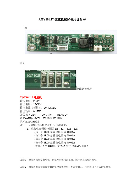
XQY10L17恒流板配屏使用说明书图1图2电流调整电阻XQY10L17升压板输入电压:9-15V输出电压:17-60V输出电流(每组):20-400MA输出功率:0-18W开关机(O/F):ON:3-5V OFF:0-2V调光(ADJ):0-5V0V最亮5V最暗尺寸:122*23MM注:1、输出电压根据屏电压自动调整。
2、输出电流调整电阻为R8、R9、R16、R17(1)1个1R00总输出电流为100MA(2)2个1R00总输出电流为200MA(3)3个1R00总输出电流为300MA(4)4个1R00总输出电流为400MA例如:2个1R00+1个2R2组合=250MA(图2)方法1、原装屏按规格书电流,调整升压板电流电阻,就可以直接配屏使用。
方法2、组装屏有参数的按参数调整恒流板使用,不知参数的,可以按以下方法调整配屏。
第一步,先用200MA的恒流板点亮屏,测试下恒流板供给屏的电压在17-40V的可配250MA恒流板,电压在40-60V的可配200MA恒流板。
(适用于18.5-23.6寸)。
第二步,配好后点亮1小时,用手摸下屏边灯条座置,确认温度,40-55度(能长期手摸为配屏正确,不能长期手摸的说明末配好屏,可以调小电流,再次重配。
方法3、组装屏不知参数的,可计算电流配屏。
18.5寸19寸宽屏正屏功率为7--10W21.5寸宽屏正屏功率为10---13W23.6寸宽屏正屏功率为13---15W功率W除以所测到电压V=电流A,就可调整恒流板配屏。
以上3个方法配好屏,都要经过方法2第二步温度确认为准。
以上配屏资料是按常规组装屏经验所得。
本文只供参考。
如有疑问请电话联系莫工:135********QQ:59938492适用屏如下:群创:MT185GW01V.1、MT185GW01V.3、MT185GW01V.4、MT190AW02V.3、MT190AW02V.4、MT190AW02V.W、MT190EN02V.W、MT200LW02V.0、MT200LW01V.1、MT215DW02V.0、MT215DW01V.1、MT215DW01V.3、MT220WW01V.T、MT220WW01V.7、MT230DW01V.1、MT230DW01V.2、MT230DW01V.3、MT230DW03V.0、MT230DW03V.1中华:CLAA185WA04、CLAA215FA04、CLAA215FA04V2、CLAA215FA04V4、CLAA215FS05、CLAA220UA01、CLAA220UA01A奇美:M185BGE-L21、M185BGE-L23、M185BGE-L22、M185B3-LC1、M185BGE-L10、M185B3-LA1、M185B3-L01、M185B3-L03、M190E6-L0E、M190E6-L01、M190CGE-L20、M190Z3-L06、M190Z3-L01、M190Z3-L02、M190Z3-L05、M200FGJ-L2U、M200FGE-L23、M200FGE-L1A、M200O3-LA3、M200FGE-L20、M200O3-LA1、M200O3-L01、M215HGJ-L2U、M215HGG-L10、M215HGE-L23、M215HGE-L21、M215HGJ-L21、M215H3-L03、M215H3-LA5、M215HGE-L1A、M215HGE-L10、M215H3-LA1、M215H3-L01、M220Z2-L02、M220J3-L01、M220Z3-L01、M220Z3-LA3、M220ZGE-L20、M220Z3-LA1、M220Z3-L07、M220Z3-L03、M220Z2-L01、M230HGE-L20、M236HGJ-L1U、M236HGE-L23、M236HGE-L20、M236HGJ-L11、M236HGE-L10、M236H3-LA3、M236H5-LA3、M236H3-L05、M236H3-LA2、M236H3-L02、M236H3-L01、M236HHF-L11、M236H5-L0A、M270HGE-L20、M270HGE-L10、M270H5-LA2、M270H3-L03、M270HHF-L10、M270H3-L01、、V185BG2-LE1、V185B1-LE2、V185B1-LE1、V215H1-LE1、V215H1-LE2、V236H1-LE6、V236H4-LE1、V236H3-LH3、V236H1-LE4、V236H1-LE3、V236H1-LE1、V236H3-LS1、V236H1-LE2、V236H1-DE01、TT260GW01V.0、V260B3-LE1、V260B3-LE2、V260H1-LE1、V260H1-LE2、V260B2-LE1、V260B2-DE03友达(AUO):M185XTN01.0、M185XW01VG、M185XW01VF、M185XW01VD、M185XW01 VE、M185XW01V3、M185HW01V6、M185HW01VD、M185XW01V6、M185XW01V7、M190EG02V9、M190PW01V8、M200RW01V6、M201UN02V0、M201SP01V2、M201EW02 VE、M215HW03V1、M215HW02V0、M215HW01VE、M215HW01VB、M215HW01V8、M215HW01V6、M230UW01V0、M240HW01VD、M240HW02V6、M240HW02V1、M240HW01VB、M240HW01V9、M240HW01V6、M240HW01V1、M270HW01V2、M270HW02V3、M270HW02V2、M270HW02V1、M270HW02V0、、T240XVN01.0、T240HW01V0、T260XVN01.4、T260XW06V4、T260XW06V5、T260XW06V1、T260XW06 V2、T260XW06V0、T260XW05V5、京东方(BOE):HM185WX1-400、HM185XW1-400、HM215WU1-500、HT185WX1-300、HT215F01-100、HT260WXC-200、LG:LM185WH2-TLA3、LM185WH2-TLC1、LM185WH2-TLA1、LM190E09-TLB2、LM190E09-TLC1、LM190E09-TLA1、LM190E09-TLB1、LM200WD3-TLC7、LM200WD3-TLA4、LM200WD4-SLB1、LM200WD3-TLC1、LM200WD3-TLA5、LM200WD3-TLA3、LM200WD3-TLA2、LM200WD3-TLA1、LM215WF8-TLA1、LM215WF5-SLA1、LM215WF3-SLC5、LM215WF3-SLC2、LM215WF4-TLA2、LM215WF3-SDC2、LM215WF3-SDB1、LM215WF4-TLE1、LM215WF4-TLE7、LM215WF3-SLC1、LM215WF4-TLA4、LM215WF4-TLA3、LM215WF4-TLA1、LM215WF3-SLA1、LM215WF3-SDA1、LM220WE5-TLC1、LM220WE5-TLA2、LM220WE5-TLA1、LM230WF3-SLD1、LM230WF5-TLB1、LM230WF8-TLA3、LM230WF3-SLB2、LM230WF5-TLD5、LM230WF5-TLD2、LM230WF5-TLD1、LM230WF5-TLC2、LM230WF5-TLC1、LM230WF5-TLA2、LM230WF5-TLA3、LM230WF8-TLA1、LM230WF6-SLA1、LM230WF3-SLB1、LM230WF5-TLA1、LM240WU8-SLA1、LM240WU8-SLA2、LM240WU6-SDA1、LM240WU5-SLA1、LM270WF5-SLB1、LM270WQ1-SDE3、LM270WQ1-SLA1、LM270WF3-TLA1、LM270WQ1-SDC2、LM270WF2-TLA5、LM270WF2-TLA1、LM270WQ1-SDA2、三星:LTM185AT05、LTM185AT04、LTM185AT04-V、LTM190BT08、LTM200KT10、LTM200KT08-W02、LTM200KT08-V、LTM200KT07、LTM200KT05、LTM215HT04、LTM215HT03、LTM220MT04、LTM220MT09、LTM230HL01、LTM230HT10、LTM230HT09、LTM230HT05、LTM230HT04、LTM240CL01、LTM240CT06、LTM240CS02、LTM270HT03、LTM270DL02、龙腾:M190MWW4R2、M236MWF2R0、M236MWF1R116L0354、组装屏:M190ID1WW3-1、T260B2-P03-L01、天马:TM190MDS01、TM240320A7NFWVGWC2-1、TM240320LNFWUG、TM240320INFWG1、TM240320C1NFWGWC、TM240320B9NFWUGWC、TM240320B8NFWGWC、夏普:LQ185K1LGN3、LQ185K1LGN1、LQ185T1LGN3、LQ185T1LGN2、LQ190E1LW52、LQ190E1LX51、LQ190E1LW51、LQ215M1LGN2、LQ215M1LXXX、LQ220AC9001、LQ230M1LW1110PM156B3-L01V260H1-LE2、V260H1-LE312PV260B3-LE1、V260H1-LE1、M236H3-L01、M185B3-L01LM215WF4-TLA1LM215WF4-TLA3LTM200KT08W01LTM200KT10LG236LM230WF5-TLA1LM200WD3-TLCCLM215WF4-TLE1LM215WF3-SLC5LM215WF4-TLE8LM185WH2-TLC1LM215WF4-TLE2LM215WF4-TLE7LM215WF4-TLE9M230WA01-EDLM220WE5-TLC1CLAA185WA04MT190AW02V.4 LM185WH2-TLA1 MT185GW01V.4 MT215DW02-V.0 TPM190A1-LOGM185XW01V7 CLAA215FA04 CLAA185WA04 CLAA215WA04-K CLAA185WA04-KMT190AW02-V.W MT200LW02V.0 M200FGE-L1ALM220WE5-TLA1 M185XW01-V6M215H3-LA1M215H3-LA5M185B3-LA1V216B1-LE1M22023-LA1LM220WE5-TLA1M236H3-LA2V236H1-LE2 HCGD19V236CDH11-2M236IDEWF1LTM170ET01A150XN01A150X1V01V2 PV200WLEDM-P21HM230WA01-ED TPM190A1-MWW3MTPV190WLEDM-V53H M215HW01V7TM104SDH01V1.0 LTM190BT08、TPM190A1-MWW3PV220WLEDM-P21H LTM185AT04M190MWW4AU M185XW01-VDM215HGE-L10AU M215HW01-VB LTM215HT03MT215DW01-V.1MT215DW01-V.3MT215DW01-V.2LQ215M1LGN2LQ215M1LXXXMT230DW01M215HW01-V6MT185GW01-V.1MT185GW01V0MT185GW01V2MT185GW01V3LQ185K1LXXXLQ185T1GN3M236H3-L01M185B3-L01M156B3-L01V260H1-LE1V260H1-LE3M240HW02V.1V216H1-LE1V215H1-LE1V215H3-LA1V236H1-L01M240HW01VBM240HW01V6LM230WF3-SLC1LM230WF5-TLA(C)1M215HGJ-L22M215HW01V6TPT260B2-TWR1M236MWF2M215HGE-L1AM215FGE-L1ALM230WF5-TLD1LM230WF5-TLA3M215HW03V.1M185BGE-L10AU M190PW01V8M215H1-P01-LE2M215HGJ-L21LM200WD3-TLC7(9) LTM270HT03M215HW02V.0LM230WF8-TLA1LM230WF5-TLF1LM230WF3-SLC1 LTM230HT10M236HGE-L10M236HGE-L20M230HGE-L20MT230DW03V.0M240HW01V1M236H1-P01M200TGE-L20M200O3-LA3M200O1-L07M200O1-L02LM215WF3-SLC5M190Z3-L06LTM200KT08-W01V260H1-LE2V260B3-LE1M185XW01V.3LM185EXNM200FGJ-L20REV.C1 LQ215M1LGN2LM270WF4-TLA1LM270WF6-SLC1CL2160000V236H1-LE4T260XW06V5M156B3-L01HT215F01-100M190CGE-L20LM200WD4-SLB2 LM200WD3-TLF1 LM215WF3-SLE1 LM230WF5-TLF1 LM230WF5-TLF2 LM230WF5-TLD1 LM230WF3-SSA1 LM270WF6-SSZ1 LM270WF6-SLZ1AUO A150XN01V.2M156BGE-L10M156BGE-L01M200FGE-L23T240XVN01.0HT185WX1-100LM215WF7-SLB1。

Dell Chassis Management Controller Firmware 版本 3.0 用户指南注和小心____________________本出版物中的信息如有更改,恕不另行通知。
© 2010 Dell Inc. 版权所有,翻印必究。
未经 Dell Inc. 书面许可,严禁以任何形式复制这些材料。
本文中使用的商标:Dell ™、DELL 徽标、FlexAddress ™、OpenManage ™、PowerEdge ™ 和 PowerConnect ™ 是 Dell Inc.的商标。
Microsoft ®、Active Directory ®、Internet Explorer ®、Windows ®、Windows Server ® 和 Windows Vista ® 是 Microsoft Corporation 在美国和其他国家/地区的商标或注册商标。
Red Hat ® 和 Red HatEnterprise Linux ® 是 Red Hat, Inc. 在美国和其它国家/地区的注册商标。
Novell ® 和 SUSE ® 分别是 Novell Inc. 在美国和其它国家/地区的注册商标和商标。
Intel ® 是 Intel Corporation 的注册商标。
UNIX ® 是 The Open Group 在美国和其它国家/地区的注册商标。
Avocent ® 是 Avocent Corporation 的商标。
OSCAR ® 是 Avocent Corporation 或其子公司的注册商标。
版权 1998-2006 The OpenLDAP Foundation 。
All rights reserved (版权所有,翻印必究)。
MacroSAN MS5520G2-HG系列存储设备安装手册文档版本:V1.01杭州宏杉科技股份有限公司400-650-5527声明版权所有©2022杭州宏杉科技股份有限公司。
保留所有权利。
未经杭州宏杉科技股份有限公司书面许可,任何单位和个人不得擅自摘抄本手册的内容,且不得以任何形式传播本手册。
本手册仅作为操作参考,由于软件版本升级或其他原因,本手册的内容可能滞后于最新的软件版本或设备配置,杭州宏杉科技股份有限公司保留在没有任何通知或提示的情况下对本手册的内容进行修改的权利。
商标信息MacroSAN、ODSP、ODSP_MSC、ODSP_JMC、ODSP Scope、宏杉均为杭州宏杉科技股份有限公司的商标。
对于本手册中出现的其他公司的商标、产品标识及商品名称,由各自权利人拥有。
目录MacroSAN MS5520G2-HG系列存储设备 ............................................................................................ 1-1安装手册............................................................................................................................................... 1-1声明 ...................................................................................................................................................... 1-2商标信息............................................................................................................................................... 1-2目录 ...................................................................................................................................................... 1-3图目录................................................................................................................................................... 1-8表目录................................................................................................................................................. 1-12 1前言 ................................................................................................................................................. 1-141.1 读者对象.......................................................................................................................................... 1-141.2 适用范围.......................................................................................................................................... 1-141.3 文档结构.......................................................................................................................................... 1-141.4 文档约定.......................................................................................................................................... 1-151.4.1 手册描述约定........................................................................................................................ 1-151.4.2 其他约定 ............................................................................................................................... 1-161.5 术语................................................................................................................................................. 1-161.5.1 DSU ...................................................................................................................................... 1-161.5.2 EMC ...................................................................................................................................... 1-161.5.3 EP ......................................................................................................................................... 1-161.5.4 FC ......................................................................................................................................... 1-161.5.5 GE ........................................................................................................................................ 1-161.5.6 GUI ....................................................................................................................................... 1-161.5.7 iSCSI .................................................................................................................................... 1-161.5.8 ODSP ................................................................................................................................... 1-171.5.9 ODSP Scope ........................................................................................................................ 1-171.5.10 ODSP Scope+ .................................................................................................................... 1-171.5.11 SAN .................................................................................................................................... 1-171.5.12 SAS .................................................................................................................................... 1-171.5.13 SATA .................................................................................................................................. 1-171.5.14 SP ....................................................................................................................................... 1-171.5.15 SPU .................................................................................................................................... 1-171.5.16 SSD .................................................................................................................................... 1-171.6 资料获取方式................................................................................................................................... 1-181.7 资料意见或建议反馈方式 ................................................................................................................ 1-18 2设备使用注意事项............................................................................................................................ 2-182.1 用电安全注意事项 ........................................................................................................................... 2-182.2 防静电安全注意事项........................................................................................................................ 2-182.2.2 无防静电腕带时紧急操作方法............................................................................................... 2-192.3 激光安全注意事项 ........................................................................................................................... 2-192.4 电池安全注意事项 ........................................................................................................................... 2-192.5 EMC注意事项................................................................................................................................. 2-202.6 磁盘使用注意事项 ........................................................................................................................... 2-202.7 操作安全注意事项 ........................................................................................................................... 2-21 3产品介绍 .......................................................................................................................................... 3-223.1 产品概述.......................................................................................................................................... 3-223.2 产品规格.......................................................................................................................................... 3-223.2.1 SPU规格 .............................................................................................................................. 3-223.2.2 DSU规格.............................................................................................................................. 3-233.2.3 磁盘模块规格........................................................................................................................ 3-243.3 产品外观.......................................................................................................................................... 3-253.3.1 SPU外观 .............................................................................................................................. 3-253.3.2 DSU2625外观...................................................................................................................... 3-303.3.3 DSU2624外观...................................................................................................................... 3-343.3.4 DSU2725外观...................................................................................................................... 3-383.3.5 磁盘模块外观........................................................................................................................ 3-423.4 产品指示灯 ...................................................................................................................................... 3-443.4.1 SP指示灯 ............................................................................................................................. 3-443.4.2 SPU风扇模块+电池模块指示灯 ........................................................................................... 3-453.4.3 IO插卡指示灯....................................................................................................................... 3-453.4.4 DSU指示灯 .......................................................................................................................... 3-473.4.5 EP指示灯 ............................................................................................................................. 3-473.4.6 DSU风扇模块指示灯............................................................................................................ 3-483.4.7 电源模块指示灯 .................................................................................................................... 3-483.4.8 磁盘模块指示灯 .................................................................................................................... 3-48 4安装设备 .......................................................................................................................................... 4-494.1 安装规划.......................................................................................................................................... 4-494.2 安装流程.......................................................................................................................................... 4-494.3 安装前准备 ...................................................................................................................................... 4-504.3.1 准备安装场所........................................................................................................................ 4-504.3.2 准备机柜 ............................................................................................................................... 4-534.3.3 准备安装工具........................................................................................................................ 4-544.4 安装前检查 ...................................................................................................................................... 4-554.4.1 检查环境 ............................................................................................................................... 4-554.4.2 检查设备 ............................................................................................................................... 4-564.5 安装机柜.......................................................................................................................................... 4-584.5.1 安装机柜 ............................................................................................................................... 4-584.5.2 安装机柜后检查 .................................................................................................................... 4-584.6 安装托架式滑道............................................................................................................................... 4-594.6.1 托架式滑道介绍 .................................................................................................................... 4-594.6.2 确定滑道位置........................................................................................................................ 4-604.6.3 安装滑道 ............................................................................................................................... 4-604.6.4 安装滑道后检查 .................................................................................................................... 4-624.7 安装浮动螺母(可选).................................................................................................................... 4-624.7.1 浮动螺母介绍........................................................................................................................ 4-624.7.2 安装浮动螺母到机柜内 ......................................................................................................... 4-634.8 安装SPU ......................................................................................................................................... 4-634.8.1 安装SPU流程...................................................................................................................... 4-634.8.2 安装SPU到机柜中............................................................................................................... 4-644.8.3 安装SPU风扇模块+电池模块(可选)................................................................................ 4-654.8.4 安装SPU磁盘模块和磁盘假面板(可选)........................................................................... 4-664.8.5 安装SPU后检查 .................................................................................................................. 4-664.9 安装DSU......................................................................................................................................... 4-674.9.1 安装DSU流程...................................................................................................................... 4-674.9.2 安装DSU到机柜中............................................................................................................... 4-684.9.3 安装DSU磁盘模块和磁盘假面板(可选) .......................................................................... 4-684.9.4 安装DSU后检查 .................................................................................................................. 4-694.10 安装线缆........................................................................................................................................ 4-694.10.1 布线注意事项...................................................................................................................... 4-694.10.2 安装线缆流程...................................................................................................................... 4-724.10.3 安装接地线.......................................................................................................................... 4-734.10.4 安装电源线.......................................................................................................................... 4-744.10.5 安装SAS线缆 .................................................................................................................... 4-764.10.6 安装SP业务接口线缆 ........................................................................................................ 4-824.10.7 安装SP管理网口线缆 ........................................................................................................ 4-864.10.8 安装客户端服务器线缆 ....................................................................................................... 4-864.10.9 安装线缆后检查 .................................................................................................................. 4-87 5启动与配置设备 ............................................................................................................................... 5-875.1 设备上电前检查............................................................................................................................... 5-875.2 设备上电及启动............................................................................................................................... 5-885.2.1 DSU上电及启动 ................................................................................................................... 5-885.2.2 DSU启动后检查 ................................................................................................................... 5-885.2.4 SPU启动后检查 ................................................................................................................... 5-895.3 设备配置.......................................................................................................................................... 5-895.3.1 设备默认配置........................................................................................................................ 5-895.3.2 设备配置准备........................................................................................................................ 5-905.3.3 设备配置 ............................................................................................................................... 5-905.4 设备关机及下电............................................................................................................................... 5-92 6安装与拆卸设备组件 ........................................................................................................................ 6-936.1 安装与拆卸设备组件速查表............................................................................................................. 6-936.2 安装/拆卸SP ................................................................................................................................... 6-946.2.1 SP介绍................................................................................................................................. 6-946.2.2 安装SP ................................................................................................................................. 6-946.2.3 拆卸SP ................................................................................................................................. 6-956.3 安装/拆卸SPU风扇模块+电池模块................................................................................................. 6-956.3.1 SPU风扇模块+电池模块介绍 ............................................................................................... 6-956.3.2 安装SPU风扇模块+电池模块 .............................................................................................. 6-966.3.3 拆卸SPU风扇模块+电池模块 .............................................................................................. 6-966.3.4 安装电池模块到风扇模块中 .................................................................................................. 6-976.3.5 从风扇模块中拆卸电池模块 .................................................................................................. 6-976.4 安装/拆卸IO插卡............................................................................................................................ 6-986.4.1 IO插卡介绍........................................................................................................................... 6-986.4.2 安装/拆卸IO插卡 ................................................................................................................. 6-986.5 安装/拆卸EP ................................................................................................................................. 6-1006.5.1 安装/拆卸DSU2625 EP ...................................................................................................... 6-1006.5.2 安装/拆卸DSU2624 EP ...................................................................................................... 6-1016.5.3 安装/拆卸DSU2725 EP ...................................................................................................... 6-1026.6 安装/拆卸DSU风扇模块............................................................................................................... 6-1036.6.1 安装/拆卸DSU2625风扇模块 ............................................................................................ 6-1036.6.2 安装/拆卸DSU2624风扇模块 ............................................................................................ 6-1046.6.3 安装/拆卸DSU2725风扇模块 ............................................................................................ 6-1056.7 安装/拆卸电源模块 ........................................................................................................................ 6-1086.7.1 电源模块介绍...................................................................................................................... 6-1096.7.2 安装电源模块...................................................................................................................... 6-1106.7.3 拆卸电源模块...................................................................................................................... 6-1106.8 安装/拆卸磁盘模块 ........................................................................................................................ 6-1116.8.1 磁盘模块介绍...................................................................................................................... 6-1116.8.2 安装/拆卸2.5英寸磁盘模块A ............................................................................................ 6-1126.8.3 安装/拆卸2.5英寸磁盘模块B ............................................................................................ 6-1136.8.4 安装/拆卸3.5英寸磁盘模块................................................................................................ 6-1156.8.5 安装磁盘假面板 .................................................................................................................. 6-117 7常见故障处理................................................................................................................................. 7-1187.1 SP故障处理 .................................................................................................................................. 7-1187.1.1 故障现象1:SP的告警指示灯闪烁或常亮 ......................................................................... 7-1187.1.2 故障现象2:SP的运行指示灯常亮或常灭 ......................................................................... 7-1197.1.3 故障现象3:SP启动过程中,LED数码管无法显示信息................................................... 7-1197.1.4 故障现象4:SP启动过程中,LED数码管停留在88 ......................................................... 7-1197.1.5 故障现象5:SP启动过程中,LED数码管长时间停留在某个固定值................................. 7-1207.2 SPU风扇模块+电池模块故障处理 ................................................................................................ 7-1207.3 EP故障处理 .................................................................................................................................. 7-1217.3.1 故障现象1:告警指示灯闪烁或常亮 .................................................................................. 7-1217.3.2 故障现象2:运行指示灯常亮或常灭 .................................................................................. 7-1217.4 DSU风扇模块故障处理................................................................................................................. 7-1227.5 电源模块故障处理 ......................................................................................................................... 7-1227.6 磁盘模块故障处理 ......................................................................................................................... 7-1237.7 其他故障处理................................................................................................................................. 7-123附录A.拇指螺钉的安装方法.............................................................................................................. 7-123附录B.中国有害物质声明 ................................................................................................................. 7-126图目录图3-1 SPU前正视图........................................................................................................................... 3-25图3-2 SPU后正视图........................................................................................................................... 3-26图3-3 SP正视图................................................................................................................................. 3-27图3-4 SPU风扇模块+电池模块正视图................................................................................................ 3-28图3-5 SPU电池模块正视图................................................................................................................ 3-29图3-6 SPU电源模块正视图................................................................................................................ 3-29图3-7 DSU2625前正视图 .................................................................................................................. 3-30图3-8 DSU2625后正视图 .................................................................................................................. 3-31图3-9 DSU2625的EP正视图............................................................................................................ 3-32图3-10 DSU2625风扇模块正视图...................................................................................................... 3-33图3-11 DSU2625电源模块正视图...................................................................................................... 3-33图3-12 DSU2624前正视图................................................................................................................. 3-34图3-13 DSU2624后正视图................................................................................................................. 3-35图3-14 DSU2624的EP正视图 .......................................................................................................... 3-36图3-15 DSU2624风扇模块正视图...................................................................................................... 3-37图3-16 DSU2624电源模块正视图...................................................................................................... 3-37图3-17 DSU2725前正视图................................................................................................................. 3-38图3-18 DSU2725后正视图................................................................................................................. 3-38图3-19 DSU2725的EP正视图 .......................................................................................................... 3-39图3-20 DSU2725后端风扇模块正视图............................................................................................... 3-40图3-21 DSU2725内置风扇模块安装位置示意图................................................................................. 3-41图3-22 DSU2725内置风扇模块外观图............................................................................................... 3-41图3-23 DSU2725电源模块正视图...................................................................................................... 3-42图3-24 2.5英寸磁盘模块A外观......................................................................................................... 3-42图3-25 2.5英寸磁盘模块B外观......................................................................................................... 3-43图3-26 2.5英寸磁盘模块前面板 ......................................................................................................... 3-43图3-27 3.5英寸磁盘模块前面板 ......................................................................................................... 3-44图4-1存储设备的安装规划示意图 ...................................................................................................... 4-49图4-2存储设备的安装流程示意图 ...................................................................................................... 4-50图4-3设备防拆封条示意图................................................................................................................. 4-57图4-4保留磁盘标签示意图................................................................................................................. 4-58图4-5带拇指螺钉托架式滑道(左侧滑道)示意图 ............................................................................. 4-59图4-6带定位销托架式滑道(左侧滑道)示意图................................................................................. 4-60。
INSTALLATION1.Refer to WARNING.2.Install as close as possible to the equipment which is being lubricated.3.Install the unit with the air flowing through the body in the direction indicated.4.Install a unit with the same pipe size as the line in use.5.The lubricator may be filled under pressure by removing the fill plug and pouring the oil into the bowl through the fill port. The bowl may be taken off after the fill plug is removed if a more rapid fill is required. Do not replace the fill plug until the bowl is in position and the clamp ring is securely locked in place.NOTE: As the fill plug is removed, the air pressure in the bowl will be released.e clean oil, preferably SAE 10 or lighter weight. The rate of oil delivery may be controlled by turning the adjusting screw counterclockwise for more and clockwise for less oil delivered. This L30 lubricator delivers all the oil downstream that passes through the sight dome. The oil delivery rate will change automatically to deliver more oil during higher airflows and less oil for airflows lower than the one at which the setting was made.NNR-NOT NORMALLY REPLACEDRichland, MI 49083Tel: (269) 629-5000Installation & Service Instructions 83-159-000Lubricator Model L30 with Variations and Accessories ISSUED: December, 2004Supersedes: August, 2002Doc.# 83-159-000, Rev. 2WARNINGTo avoid unpredictable system behavior that can cause personal injury and property damage:•Disconnect electrical supply (when necessary) before installation,servicing, or conversion.•Disconnect air supply and depressurize all air lines connected to this product before installation, servicing, or conversion.•Operate within the manufacturer’s specified pressure, temperature,and other conditions listed in these instructions.•Medium must be moisture-free if ambient temperature is below freezing.•Service according to procedures listed in these instructions.•Installation, service, and conversion of these products must be performed by knowledgeable personnel who understand how pneumatic products are to be applied.•After installation, servicing, or conversion, air and electrical supplies (when necessary) should be connected and the product tested for proper function and leakage. If audible leakage is present, or the product does not operate properly, do not put into use.•Warnings and specifications on the product should not be covered by paint, etc. If masking is not possible, contact your local representative for replacement labels.!!CAUTIONP olycarbonate bowls, being transparent and tough, are ideal for use with Filters and Lubricators. They are suitable for use in normal industrial environments, but should not be located in areas where they could be subjected to direct sunlight, an impact blow, nor temperatures outside of the rated range. As with most plastics, some chemicals can cause damage.P olycarbonate bowls should not be exposed to chlorinated hydrocarbons,ketones, esters and certain alcohols. They should not be used in air systems where compressors are lubricated with fire-resistant fluids such as phosphate ester and di-ester types.Metal bowls are recommended where ambient and/or media conditions are not compatible with polycarbonate bowls. Metal bowls resist the action of most such solvents, but should not be used where strong acids or bases are present or in salt laden atmospheres. Consult the factory for specific recommendations where these conditions exist.TO CLEAN POLYCARBONATE BOWLS USE MILD SOAP AND WATER ONLY! DO NOT use cleansing agents such as acetone, benzene, carbon tetrachloride, gasoline, toluene, etc., which are damaging to this plastic.Bowl guards are recommended for added protection of polycarbonate bowls where chemical attack may occur.MAINTENANCE1.The lubricator should remain trouble-free given clean operatingconditions. Contaminants from dirty oil can collect on bottom of bowl or on siphon tube inlet filter. After tapping filter or bowl on a hard surface, use an air gun to blow out residual dirt.2.IF OIL DELIVERY RATE DROP S, clean lubricator. Shut off airsupply and reduce pressure inside lubricator to zero. Remove Flow-Guide® variable orifice screw and clean its passage with a small wire. Check orifice screw's bore for contaminants and clean it if necessary. Be sure that passage downward from sight dome cavity into Flow-Guide® variable orifice post is open. Remove adjusting screw, clean needle and seat in body. Inspect and clean passage from needle seat to siphon tube adapter.3.Drain off contaminants that collect in bottom of bowl.REPAIR KITS AND REPLACEMENT PARTSO-Ring Repair Kit............................................................LRP-95-058 Liquid Level Switch Kit.....................................................LRP-95-093 Bowl Assembly — No Guard...........................................LRP-96-160 Plastic Petcock Kit...........................................................LRP-95-181 Siphon Tube Assembly Kit..............................................LRP-96-182 Flow-Guide® Variable Orifice Kit (3/4" Models)..............LRP-95-189 Flow-Guide® Variable Orifice Kit (1" Models).................LRP-95-190 Sight Dome Kit.................................................................LRP-95-249 Fill Plug Kit.......................................................................LRP-95-253 O-Ring Kit for Adjusting Screw.......................................GRP-95-255 Bowl O-Ring Kit..............................................................GRP-95-256 Force-Fill Adapter...........................................................GRP-96-394 Clamp Ring Assembly....................................................GRP-96-404 Tamper-Resistant Kit.......................................................LRP-95-587 Metal Gauge Bowl with Petcock.....................................GRP-95-676 Sight Gauge Kit...............................................................LRP-95-771 Bowl Guard.....................................................................GRP-95-808 Plastic Bowl with Plastic Petcock and Bowl Guard.........LRP-95-830 Plastic Bowl — No Drain.................................................LRP-96-940 Auto-Fill™ Lubricator Adapter(includes plastic bowl assembly).................................LRP-95-698 Check Ball and O-ring Kit................................................LRP-95-310WARNING!FAILURE OR IMPROPER SELECTION OR IMPROPER USE OF THE PRODUCTS AND/OR SYSTEMS DESCRIBED HEREIN OR RELATED ITEMS CAN CAUSE DEATH, PERSONAL INJ URY AND PROPERTY DAMAGE.This document and other information from The Company, its subsidiaries and authorized distributors provide product and/or system options for further investigation by users having technical expertise. It is important that you analyze all aspects of your application, including consequences of any failure and review the information concerning the product or systems in the current product catalog. Due to the variety of operating conditions and applications for these products or systems, the user, through its own analysis and testing, is solely responsible for making the final selection of the products and systems and assuring that all performance, safety and warning requirements of the application are met.The products described herein, including without limitation, product features, specifications, designs, availability and pricing, are subject to change by The Company and its subsidiaries at any time without notice.EXTRA COPIES OF THESE INSTRUCTIONS ARE AVAILABLE FOR INCLUSION IN EQUIPMENT / MAINTENANCE MANUALS THAT UTILIZE THESE PRODUCTS. CONTACT YOUR LOCAL REPRESENTATIVE.。
Doc. Number :ϭTentative SpecificationϭPreliminary SpecificationϮApproval Specification MODEL NO.: M270HGESUFFIX: L10CONTENTS1. GENERAL DESCRIPTION (5)1.1 OVERVIEW (5)1.2 GENERAL SPECIFICATIONS (5)2. MECHANICAL SPECIFICATIONS (5)3. ABSOLUTE MAXIMUM RATINGS (5)3.1 ABSOLUTE RATINGS OF ENVIRONMENT (5)3.2 ELECTRICAL ABSOLUTE RATINGS (6)3.2.1 TFT LCD MODULE (6)3.2.2 BACKLIGHT UNIT (6)4. ELECTRICAL SPECIFICATIONS (7)4.1 FUNCTION BLOCK DIAGRAM (7)4.2. INTERFACE CONNECTIONS (7)4.3 ELECTRICAL CHARACTERISTICS (9)4.3.1 LCD ELETRONICS SPECIFICATION (9)4.3.2 Vcc Power Dip Condition (11)4.3.3 BACKLIGHT UNIT (11)4.3.4 LIGHTBAR Connector Pin Assignment (12)4.4 LVDS INPUT SIGNAL SPECIFICATIONS (12)4.4.1 LVDS DATA MAPPING TABLE (12)4.4.2 COLOR DATA INPUT ASSIGNMENT (13)4.5 DISPLAY TIMING SPECIFICATIONS (14)4.6 POWER ON/OFF SEQUENCE (16)5. OPTICAL CHARACTERISTICS (17)5.1 TEST CONDITIONS (17)5.2 OPTICAL SPECIFICATIONS (17)6. RELIABILITY TEST ITEM (20)7. PACKING (21)7.1 PACKING SPECIFICATIONS (21)7.2 PACKING METHOD (21)7.3 PALLET (22)8. CMI MODULE LABEL (23)9. PRECAUTIONS (24)9.1 ASSEMBLY AND HANDLING PRECAUTIONS (24)9.2 STORAGE PRECAUTIONS (24)9.3 OPERATION PRECAUTIONS (24)9.4 SAFETY PRECAUTIONS (25)9.5 SAFETY STANDARDS (25)9.6 OTHER (25)Appendix. OUTLINE DRAWING (25)REVISION HISTORYVersion Date Page Description3.0 Dec.10, 2010 All Spec Ver.3.0 for Samsung was first issued.1. GENERAL DESCRIPTION1.1 OVERVIEWM270HGE-L10 is a 27.0” TFT Liquid Crystal Display module with WLED Backlight unit and 30 pins 2ch-LVDS interface. This module supports 1920 x 1080 Full HD mode and can display up to 16.7M colors.The converter module for Backlight is not built in.1.2 GENERAL SPECIFICATIONSItem Specification Unit Note Screen Size 597.89 (H) X 336.31 (V), (27.0 inch Diagonal) mmDriver Element a-si TFT active matrix - -Pixel Number 1920 x R.G.B. x 1080 pixel -Pixel Pitch 0.3114 (H) x 0.3114 (V) mm - Pixel Arrangement RGB vertical stripe - -Display Colors 16.7M color -Transmissive Mode Normally white - -Surface Treatment AG type, 3H hard coating, Haze 25 - -Luminance, White 300 Cd/m2Power Consumption Total 22.72 W (Max.) @ cell 7.32 W (Max.), BL 15.4 W (Typ.) (1) Note (1) The specified power consumption : Total= cell (reference 4.3.1)+BL (reference 4.3.3)2. MECHANICAL SPECIFICATIONSItem Min. Typ. Max. Unit NoteHorizontal (H) 629.5 630.0 630.5 mm(1)Module SizeVertical (V) 367.8 368.2 368.7 mmThickness (T) 13.6 14.1 14.6 mmHorizontal 603.4 603.9 604.4 mm Bezel AreaVertical 341.8 342.3 342.8 mmHorizontal - 597.89 - mm Active AreaVertical - 336.31 - mmWeight - 2850 2965 g Note (1) Please refer to the attached drawings for more information of front and back outline dimensions. 3. ABSOLUTE MAXIMUM RATINGS3.1 ABSOLUTE RATINGS OF ENVIRONMENTValueUnit Note Item SymbolMin. Max.Storage Temperature TST -20 60 ºC (1) Operating Ambient Temperature TOP 0 50 ºC (1), (2) Note (1)(a) 90 %RH Max. (Ta <= 40 ºC).(b) Wet-bulb temperature should be 39 ºC Max. (Ta > 40 ºC).(c) No condensation.Note (2) The temperature of panel surface should be 0 ºC min. and 60 ºC max.3.2 ELECTRICAL ABSOLUTE RATINGS3.2.1 TFT LCD MODULEValueItem SymbolMin. Max.Unit Note Power Supply Voltage VCCS -0.3 6.0 VLogic Input Voltage VIN -0.3 3.6 V(1) 3.2.2 BACKLIGHT UNITValueItem SymbolMin. Typ Max. Unit NoteLED Forward Current PerInput Pin IF 0 100 112 mA LED Reverse Voltage PerInput Pin VR --- 60 V(1), (2) Duty=100%LED Pulse ForwardCurrent Per Input Pin IP --- 320 mA(1), (2) Pulse WidthЉ10msec.and DutyЉ10%Note (1) Permanent damage to the device may occur if maximum values are exceeded. Function operation should be restricted to the conditions described under Normal Operating Conditions.Note (2) Specified values are for input pin of LED light bar at Ta=25±2 к(Refer to 4.3.3 and 4.3.4 for further information).4. ELECTRICAL SPECIFICATIONS4.1 FUNCTION BLOCK DIAGRAM4.2. INTERFACE CONNECTIONSPIN ASSIGNMENTPin Name Description1 RXO0- Negative LVDS differential data input. Channel O0 (odd)2 RXO0+ Positive LVDS differential data input. Channel O0 (odd)3 RXO1- Negative LVDS differential data input. Channel O1 (odd)4 RXO1+ Positive LVDS differential data input. Channel O1 (odd)5 RXO2- Negative LVDS differential data input. Channel O2 (odd)6 RXO2+ Positive LVDS differential data input. Channel O2 (odd)7 GND Ground8 RXOC- Negative LVDS differential clock input. (odd)9 RXOC+ Positive LVDS differential clock input. (odd)10 RXO3- Negative LVDS differential data input. Channel O3(odd)11 RXO3+ Positive LVDS differential data input. Channel O3 (odd)12 RXE0- Negative LVDS differential data input. Channel E0 (even)13 RXE0+ Positive LVDS differential data input. Channel E0 (even)14 GND Ground15 RXE1- Negative LVDS differential data input. Channel E1 (even)16 RXE1+ Positive LVDS differential data input. Channel E1 (even)17 GND Ground18 RXE2- Negative LVDS differential data input. Channel E2 (even)19 RXE2+ Positive LVDS differential data input. Channel E2 (even)20 RXEC- Negative LVDS differential clock input. (even)21 RXEC+ Positive LVDS differential clock input. (even)22 RXE3- Negative LVDS differential data input. Channel E3 (even)23 RXE3+ Positive LVDS differential data input. Channel E3 (even)24 GND Ground25 NC For LCD internal use only, Do not connectPin Name Description26 NC For LCD internal use only, Do not connect27 Vcc +5.0V power supply 28 Vcc +5.0V power supply 29 Vcc+5.0V power supply 30Vcc+5.0V power supplyNote (1) Connector Part No.:093G30-B0001A(STARCONN) or MSAKT2407P30HA(STM) or equivalent Note (2) User’s connector Part No:Mating Wire Cable Connector Part No.: FI-X30H(JAE) or FI-X30HL(JAE). Note (3) The first pixel is odd.4.3 ELECTRICAL CHARACTERISTICS 4.3.1 LCD ELETRONICS SPECIFICATIONValue ParameterSymbol Min. Typ. Max. Unit Note Power Supply VoltageVcc 4.5 5.0 5.5 V - Ripple Voltage V RP 300 mV - Rush CurrentI RUSH 3 A (2) White0.65 0.78 A (3)a Black1.22 1.464 A (3)b Power Supply Current Vertical Stripe1.02 1.22 A (3)c Power ConsumptionPLCD 6.1 7.32 Watt (4) LVDS differential input voltage Vid 200 600 mV LVDS common input voltage Vic 1.2 V Logic High Input Voltage VIH 2.64 3.6 V Logic Low Input Voltage VIL-0.30.66VNote (1) The ambient temperature is Ta = 25 ± 2 ºC.Note (2) Measurement Conditions:Note (3) The specified power supply current is under the conditions at Vcc = 5.0 V, Ta = 25 ± 2 ºC, Fr = 60Hz, whereas a power dissipation check pattern below is displayed.Note (4) The power consumption is specified at the pattern with the maximum current.Note (5) VID waveform condition4.3.2 Vcc Power Dip Condition4.3.3 BACKLIGHT UNITValue Parameter Symbol Min. Typ. Max. Unit Note LED Light Bar Input Voltage Per Input Pin VPIN 33.6 38.4 42 V (1), Duty=100%, IPIN=100mA LED Light Bar CurrentPer Input Pin IPIN 0 100 112 mA (1), (2) Duty=100%LED Life Time LLED 30000 -- -- Hrs (3) Power ConsumptionPBL---15.416.8W(1)Duty=100%, IPIN=100mANote (1) LED light bar input voltage and current are measured by utilizing a true RMS multimeter as shownbelow:Note (2) PBL = IPIN × VPIN × ( 4 ) input pins , LED light bar circuit is (12)Series, (4)Parallel.Note (3) The lifetime of LED is defined as the time when LED packages continue to operate under theconditions at Ta = 25 ±2 к and I= (25)mA (per chip) until the brightness becomes Љ 50% of its original value.4.3.4 LIGHTBAR Connector Pin AssignmentConnector: 3707K-Q06N-01L(ENTERY) or CI1406M1HRE-NH (CviLux).CN1Pin number Description1 Cathode of LED string2 Cathode of LED string3 VLED4 VLED5 Cathode of LED string6 Cathode of LED string4.4 LVDS INPUT SIGNAL SPECIFICATIONS4.4.1 LVDS DATA MAPPING TABLELVDS output D7 D6 D4 D3 D2 D1 D0 LVDS Channel O0Data order OG0 OR5 OR4 OR3 OR2 OR1 OR0LVDS output D18 D15 D14 D13 D12 D9 D8 LVDS Channel O1Data order OB1 OB0 OG5 OG4 OG3 OG2 OG1LVDS output D26 D25 D24 D22 D21 D20 D19 LVDS Channel O2Data order DE NA NA OB5 OB4 OB3 OB2LVDS output D23 D17 D16 D11 D10 D5 D27 LVDS Channel O3Data order NA OB7 OB6 OG7 OG6 OR7 OR6LVDS output D7 D6 D4 D3 D2 D1 D0 LVDS Channel E0Data order EG0 ER5 ER4 ER3 ER2 ER1 ER0LVDS output D18 D15 D14 D13 D12 D9 D8 LVDS Channel E1Data order EB1 EB0 EG5 EG4 EG3 EG2 EG1LVDS output D26 D25 D24 D22 D21 D20 D19 LVDS Channel E2Data order DE NA NA EB5 EB4 EB3 EB2LVDS output D23 D17 D16 D11 D10 D5 D27 LVDS Channel E3Data order NA EB7 EB6 EG7 EG6 ER7 ER64.4.2 COLOR DATA INPUT ASSIGNMENTThe brightness of each primary color (red, green and blue) is based on the 8-bit gray scale data input for the color. The higher the binary input, the brighter the color. The table below provides the assignment of color versus data input.Data SignalRed Green Blue ColorR7 R6 R5 R4 R3 R2 R1 R0 G7 G6 G5 G4 G3 G2 G1 G0 B7 B6 B5 B4 B3 B2 B1 B0Basic ColorsBlackRedGreenBlueCyanMagentaYellowWhite111111111111111111111111111111111111111111111111111111111111111111111111111111111111111111111111Gray Scale Of Red Red(0) / DarkRed(1)Red(2)::Red(253)Red(254)Red(255)::111::111::111::111::111:1111::111:11:::::::0:::::::::::::::::::::0Gray Scale Of Green Green(0) / DarkGreen(1)Green(2)::Green(253)Green(254)Green(255)::::::::::::::::::111::111::111::111::111::1111::111::11::::::::::::::::Gray Scale Of Blue Blue(0) / DarkBlue(1)Blue(2)::Blue(253)Blue(254)Blue(255)::::::::::::::::::::::::::::::::::111::111::111::111::111::1111::111::11Note (1) 0: Low Level Voltage, 1: High Level Voltage4.5 DISPLAY TIMING SPECIFICATIONSThe input signal timing specifications are shown as the following table and timing diagram.SignalItem Symbol Min. Typ. Max. Unit Note Frequency Fc 54.54 74 98 MHz - Period Tc - 13.5 - ns Input cycle tocycle jitter T rcl-0.02*Tc - 0.02*Tc ns (1) Input Clockto data skew TLVCCS -4000 400 ps (2)Spreadspectrum modulation range Fclkin_mod 0.98*Fc1.02*FcMHzLVDS ClockSpread spectrummodulation frequency F SSM200 KHz (3)Frame RateFr 47 60 75 Hz Tv=Tvd+Tvb Total Tv 1105 1125 1136 Th -Active Display Tvd 1080 1080 1080 Th - Vertical Display TermBlank Tvb Tv-Tvd 45 Tv-Tvd Th - Total Th 1050 1100 1150 Tc Th=Thd+ThbActive Display Thd 960 960 960 Tc - Horizontal DisplayTermBlankThbTh-Thd140Th-ThdTc- Note: Because this module is operated by DE only mode, Hsync and Vsync input signals are ignored.INPUT SIGNAL TIMING DIAGRAMNote (1) The input clock cycle-to-cycle jitter is defined as below figures. Trcl = I T1 – TINote (2) Input Clock to data skew is defined as below figures.Note (3) The SSCG (Spread spectrum clock generator) is defined as below figures.4.6 POWER ON/OFF SEQUENCEThe power sequence specifications are shown as the following table and diagram.Timing Specifications:ValuesParametersMin Typ. Max UnitsT1 0.5 -- 10 msT2 0 -- 50 msT3 450 -- -- msT4 90 -- -- msT5 0 -- 50 msT6 0.5 -- 100 msT7 500 -- -- msNote (1) The supply voltage of the external system for the module input should be the same as the definition of Vcc.Note (2) When the backlight turns on before the LCD operation of the LCD turns off, the display may momentarily become abnormal screen.Note (3) In case of VCC = off level, please keep the level of input signals on the low or keep a high impedance.Note (4) T4 should be measured after the module has been fully discharged between power off and on period.Note (5) Interface signal shall not be kept at high impedance when the power is on.Note (6) CMI wonϗt take any responsibility for the products which are damaged by the customers not following the Power Sequence.Note (7) There might be slight electronic noise when LCD is turned off (even backlight unit is also off). To avoid this symptom, we suggest "Vcc falling timing" to follow "t6 spec".5. OPTICAL CHARACTERISTICS 5.1 TEST CONDITIONSItemSymbol Value UnitAmbient Temperature Ta 25±2 oC Ambient Humidity Ha 50±10 %RH Supply Voltage V CC 5 VInput SignalAccording to typical value in "3. ELECTRICAL CHARACTERISTICS"LED Light Bar Input CurrentPer Input Pin I PIN 100 ± 2.4 mA PWM Duty RatioD100%LED Light Bar Test ConverterCMI 27-D0417455.2 OPTICAL SPECIFICATIONSThe relative measurement methods of optical characteristics are shown in 5.2. The following items should be measured under the test conditions described in 5.1 and stable environment shown in Note (5).ItemSymbol ConditionMin.Typ. Max.UnitNoteRx 0.639 RedRy 0.339Gx 0.309Green Gy 0.619 Bx 0.156Blue By 0.059Wx 0.313 Color Chromaticity (CIE 1931)WhiteWy Typ – 0.03 0.329Typ + 0.03-(1), (5)Center Luminance of White(Center of Screen)L C 250 300 - cd/m 2 (4), (5) Contrast Ratio CR θx =0°, θY =0° CS-2000 R=G=B=255 Gray scale 800 1200 - - (2), (5) T R - 0.8 2.5 Response Time T F θx =0°, θY =0° - 2.6 5.5 ms (3) White VariationδW θx =0°, θY =0° USB2000 - - (1.33) -(5), (6)Horizontal θx- + θx+ 150 170 - Viewing Angle Vertical θy- + θy+ CR Њ 10 USB2000 140 160 - Deg. (1), (5) Horizontal θx- + θx+ 160 178 --- Viewing AngleVerticalθy- + θy+CR Њ 5 USB2000 150170---Deg. (1), (5)Note (1) Definition of Viewing Angle (θx, θy):Note (2) Definition of Contrast Ratio (CR):The contrast ratio can be calculated by the following expression.Contrast Ratio (CR) = L255 / L0L255: Luminance of gray level 255L 0: Luminance of gray level 0CR = CR (5)CR (X) is corresponding to the Contrast Ratio of the point X at Figure in Note (6). Note (3) Definition of Response Time (T R, T F):Note (4) Definition of Luminance of White (L C):Measure the luminance of gray level 255 at center pointL C = L (5)L (x) is corresponding to the luminance of the point X at Figure in Note (6).Note (5) Measurement Setup:The LCD module should be stabilized at given temperature for 20 minutes to avoid abrupt temperature change during measuring. In order to stabilize the luminance, the measurement should be executed after lighting Backlight for 20 minutes in a windless room.Note (6) Definition of White Variation (δW):Measure the luminance of gray level 255 at 9 pointsδW = ( Minimum [L (1) ~ L (9)] / Maximum [L (1) ~ L (9)] ) *100%6. RELIABILITY TEST ITEMItemsRequired ConditionNote Temperature Humidity Bias (THB) Ta= 50к , 80%RH, 240hours High Temperature Operation(HTO)Ta= 50к , 50%RH , 240hoursLow Temperature Operation(LTO)Ta= 0к , 240hours High Temperature Storage (HTS) Ta= 60к , 240hours Low Temperature Storage (LTS)Ta= -20к , 240hours Vibration Test (Non-operation) Acceleration: 1.5 GrmsWave: Half-sineFrequency: 10 - 300 Hz Sweep: 30 Minutes each Axis (X, Y, Z)Shock Test (Non-operation) Acceleration: 50 G Wave: Half-sine Active Time: 11 msDirection : ± X, ± Y , ± Z.(one time for each Axis)Thermal Shock Test (TST) -20к/30min , 60к / 30min , 100cyclesOn/Off Test 25к ,On/10sec , Off /10sec , 30,000cyclesESD (Electro Static Discharge) Contact Discharge: ± 8KV,150pF(330Ω)Air Discharge: ± 15KV, 150pF(330Ω)Altitude Test Operation:10,000 ft / 24hoursNon-Operation:30,000 ft / 24hoursNote (1) criteria : Normal display image with no obvious non-uniformity and no line defect. Note (2) Evaluation should be tested after storage at room temperature for more than two hourNote (3) At testing Vibration and Shock, the fixture in holding the module has to be hard and rigid enough sothat the module would not be twisted or bent by the fixture.The fixing condition is shown as below:7. PACKING7.1 PACKING SPECIFICATIONS(1) 7 LCD modules / 1 Box(2) Box dimensions: 720(L) X 360(W) X 480(H) mm(3) Weight: approximately: (25.83) Kg ( 7 modules per box)!7.2 PACKING METHOD(1) Carton Packing should have no failure in the following reliability test items.Test Item Test Conditions Note Vibration ISTA STANDARDRandom, Frequency Range: 1 – 200 Hz Top & Bottom: 30 minutes (+Z), 10 min (-Z),Right & Left: 10 minutes (X) Back & Forth 10 minutes (Y)Non Operation Dropping Test1 Angle, 3 Edge, 6 Face, ISTA 45.7cmNon OperationFigure. 7-1 Packing method7.3 PALLETFor ocean shippingFor air transportFigure. 7-2 Packing method8. CMI MODULE LABELThe barcode nameplate is pasted on each module as illustration, and its definitions are as followingexplanation.(a) Model Name: M270HGE-L10(b) Revision: Rev. XX, for example: A0, A1… B1, B2… or C1, C2…etc.(c) CMI barcode definition:Serial ID: XX-XX-X-XX-YMD-L-NNNNCode Meaning DescriptionXX CMI internal use -XX Revision Cover all the changeX CMI internal use -XX CMI internal use -YMD Year, month, day Year: 0~9, 2001=1, 2002=2, 2003=3…2010=0, 2011=1, 2012=2…Month: 1~12=1, 2, 3, ~, 9, A, B, CDay: 1~31=1, 2, 3, ~, 9, A, B, C, ~, W, X, Y, exclude I, O, and U.L Product line # Line 1=1, Line 2=2, Line 3=3, …NNNN Serial number Manufacturing sequence of product (d) Customer’s barcode definition:Serial ID: CM-R0E10-X-X-X-XX-L-XX-L-YMD-NNNNCode Meaning DescriptionCM Supplier code CMI=CMR0305 Model number M270HGE-L10= R0E10X Revision code Non ZBD: 1,2,~,8,9 / ZBD: A~ZX Source driver IC code X Gate driver IC codeCentury=1, CLL=2, Demos=3, Epson=4, Fujitsu=5, Himax=6, Hitachi=7, Hynix=8, LDI=9, Matsushita=A, NEC=B, Novatec=C, OKI=D, Philips=E, Renasas=F, Samsung=G, Sanyo=H, Sharp=I, TI=J, Topro=K, Toshiba=L, Windbond=MXX Cell location Tainan Taiwan=TN, Ningbo China=CN L Cell line # 1,2,~,9,A,B,~,Y,ZXX Module location Tainan, Taiwan=TN ; Ningbo China=NP L Module line # 1,2,~,9,A,B,~,Y,ZYMD Year, month, day Year: 0~9, 2001=1, 2002=2, 2003=3…2010=0, 2011=1, 2012=2…Month: 1~12=1, 2, 3, ~, 9, A, B, CDay: 1~31=1, 2, 3, ~, 9, A, B, C, ~, T, U, VNNNN Serial number By LCD supplier(e) FAB ID(UL Factory ID):Region Factory IDTWCMI GEMNNBCMI LEOONBCME CANONHCMI CAPG9. PRECAUTIONS9.1 ASSEMBLY AND HANDLING PRECAUTIONS(1) Do not apply rough force such as bending or twisting to the module during assembly.(2) To assemble or install module into user’s system can be only in clean working areas. The dust and oilmay cause electrical short or worsen the polarizer.(3) It’s not permitted to have pressure or impulse on the module because the LCD panel and Backlight willbe damaged.(4) Always follow the correct power sequence when LCD module is connecting and operating. This canprevent damage to the CMOS LSI chips during latch-up.(5) Do not pull the I/F connector in or out while the module is operating.(6) Do not disassemble the module.(7) Use a soft dry cloth without chemicals for cleaning, because the surface of polarizer is very soft andeasily scratched.(8) It is dangerous that moisture come into or contacted the LCD module, because moisture may damageLCD module when it is operating.(9) High temperature or humidity may reduce the performance of module. Please store LCD module withinthe specified storage conditions.(10)When ambient temperature is lower than 10ºC may reduce the display quality. For example, theresponse time will become slowly.9.2 STORAGE PRECAUTIONS(1) Do not leave the module in high temperature, and high humidity for a long time. It is highly recommendedto store the module with temperature from 0кto 35кand relative humidity of less than 70%(2) Do not store the TFT – LCD module in direct sunlight(3) The module should be stored in dark place. It is prohibited to apply sunlight or fluorescent light in storing9.3 OPERATION PRECAUTIONS(1) The LCD product should be operated under normal condition.Normal condition is defined as below :Temperature : 20±15кHumidity: 65±20%Display pattern : continually changing pattern(Not stationary)(2) If the product will be used in extreme conditions such as high temperature, high humidity, highaltitude ,display pattern or operation time etc…It is strongly recommended to contact CMI for application engineering advice . Otherwise, Its reliability and function may not be guaranteed.9.4 SAFETY PRECAUTIONS(1) If the liquid crystal material leaks from the panel, it should be kept away from the eyes or mouth. In caseof contact with hands, skin or clothes, it has to be washed away thoroughly with soap.(2) After the module’s end of life, it is not harmful in case of normal operation and storage.9.5 SAFETY STANDARDSThe LCD module should be certified with safety regulations as follows:Requirement Standard remark UL UL60950-1:2006 or Ed.2:2007cUL/CSA CAN/CSA C22.2 No.60950-1-03 or 60950-1-07CB IEC60950-1:2005 / EN60950-1:2006+ A11:20099.6 OTHERWhen fixed patterns are displayed for a long time, remnant image is likely to occur.Appendix. OUTLINE DRAWING。