富士卡相机 FUJICA STX-1N 富士卡 富士STX-1n中文说明书
- 格式:pdf
- 大小:18.08 MB
- 文档页数:34
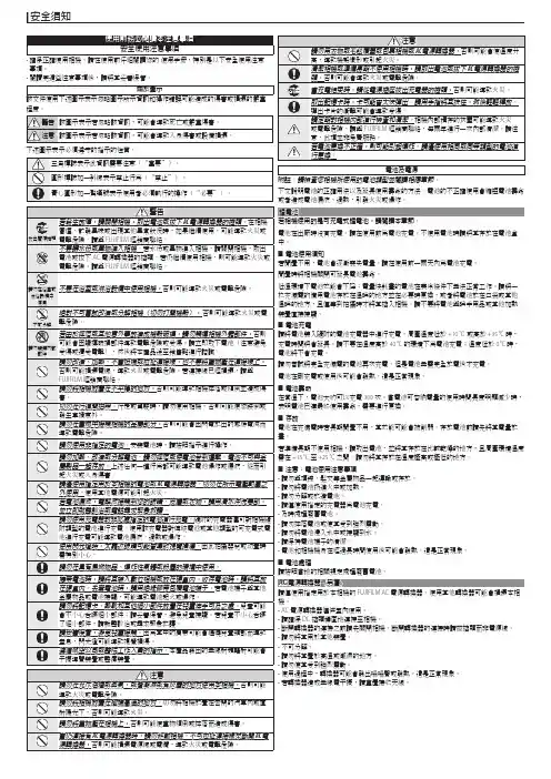
事項。
• 閱讀完這些注意事項後,請將其妥善保管。
關於圖示該文件使用下述圖示表示忽略圖示所示資訊和操作錯誤可能造成的傷害或損壞的嚴重程度。
下述圖示表示必須遵守的指示的性質。
電池及電源附註:請檢查您相機所使用的電池類型並閱讀相應章節。
下文說明電池的正確用法以及延長使用壽命的方法。
電池的不正確使用會縮短電池壽命或者造成電池漏液、過熱,引發火災或爆炸。
電池在出廠時沒有充電。
請在使用前為電池充電。
不使用電池時請將其存放在電池盒中。
■電池使用須知若閒置不用,電池會逐漸喪失電量。
請在使用前一兩天內為電池充電。
閒置時將相機關閉可延長電池壽命。
低溫環境下電池效能會下降;電量快耗盡的電池在寒冷條件下無法正常工作。
請將一枚充滿電的備用電池存放在溫暖的地方並在必要時更換,或者將電池放在口袋或其他溫暖的地方,且僅等到拍攝時才將其插入相機。
請不要將電池與暖手用品或其他加熱裝置直接接觸。
■電池充電請將電池裝入隨附的電池充電器中進行充電。
周圍溫度低於 +10 ℃或高於 +35 °C 時,充電時間將會延長。
請不要在溫度高於 40 °C 的環境下為電池充電;溫度低於 0 °C 時,電池將不會充電。
請勿嘗試將完全充滿電的電池再次充電。
但是電池無需完全放電後才充電。
電池在剛充電或使用後可能會發熱。
這是正常現象。
■電池壽命在常溫下,電池大約可以充電 300 次。
當電池可容納電量的使用時間長度明顯減少時,表明電池已達最終使用壽命,需要進行更換。
■存放電池在充滿電時若長期閒置不用,其效能可能會被削弱。
存放電池前請先將其電量放盡。
若準備長期不使用相機,請取出電池,並將其存放在比較乾燥的地方,且周圍環境溫度需在 +15 °C 至 +25 °C 之間。
請勿將其存放在溫度極高或極低的地方。
■注意:電池使用注意事項• 請勿與項鍊、髮夾等金屬物品一起運輸或存放。
• 請勿將電池扔進火中或加熱。
• 請勿分解或改造電池。

强功能、小型化._動態轉矩矢量控制用最新技術的理想的小型變頻器。
動態轉矩矢量控制實現電動機的優化控制。
>本系列變頻器體積雖小但性能高,0.5Hz時電動機的起動轉矩爲200%,~~ •一 ....... fJ 低速範圍轉矩脉動比以前的變頻器約小一半。
丨具有各種智能化功能,如自動節能、PID控制、自整定和RS485通彳I 奪,^ 並增强了維護/保護功能,如增加輸入電涌電流抑制和壽命預報等。
動態轉矩矢量控制■ Risk of Injury or Electric Shock;議:、Refer to the user's manual before installation arSope^oper. -Risk of Electric Shock* 動態轉矩矢量控制系統通過高速計算.確定電動機對^ 應負載狀態的所需功率,富士公司專有技術能最正确控1 11 (|1 1 11 I1 ' i '■1 J - I - ! 1;>wer ana-:w e r..•-;:[1j i J|辦?p制電壓和電流矢量,輸出最大轉矩。
•大起動轉矩0.5Hz時200%能平安地用於重負載,如提升和輸送系統。
亦能實現對第2電動機的轉换運行。
轉矩特性電動機[r/minl100200-300危険2.小型化參統一高度尺寸對 3.7KW及以下容量機種的高度統一爲130mm,便於設計按裝。
一※上圖表示,當FVR-E11S採用動態轉矩矢量控制驅動富士標准3相電動機〔8型系列、4極〕時的轉矩特性例,連續運行轉矩受制於所用電動機容許温升的容許負載轉矩,不是指電動機的輸出轉矩。
#糊行轉矩是表示關機的輸出轉矩。
.i130mm►减少了電動機低速範圍的轉速脉動富士獨特的On-Delay補償方法使電動機在低速範圍的轉速脉動比以前變頻器約减小一半。
轉速脉動特性以前的富士變頻器FVR-E11S 電動機速度丨r/min|參全機種都能連接制動電阻由於内部裝有制動晶體管.因此可以連接制動電阻選件.以提高再生制動能力,這樣能滿足應用在傳送帶和輸送機械時所需較大制動力的要求。
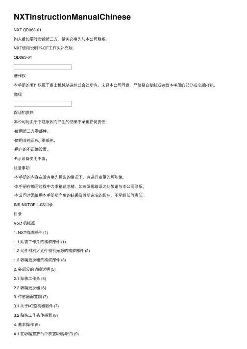
NXTInstructionManualChineseNXT QD063-01购⼊后如要转卖给第三⽅,请务必事先与本公司联系。
NXT使⽤说明书-OF⼯作头补充版-QD063-01著作权本⼿册的著作权属于富⼠机械制造株式会社所有。
未经本公司同意,严禁擅⾃复制或转载本⼿册的部分或全部内容。
商标保证和责任本公司对由于下述原因⽽产⽣的结果不承担任何责任:·使⽤第三⽅零部件。
·使⽤⾮纯正Fuji零部件。
·⽤户的不正确设置。
·Fuji设备使⽤不当。
注意事项·本⼿册的内容在没有事先预告的情况下,有进⾏变更的可能性。
·本⼿册在编写过程中⼒求精益求精,如若发现错误之处敬请与本公司联系。
·本公司对因使⽤本⼿册所产⽣的结果及其所造成的影响,不承担任何责任。
INS-NXTOF-1.0S⽬录⽬录Vol.1机械篇1. NXT构成部件 (1)1.1 贴装⼯作头的构成部件 (1)1.2 元件相机/元件相机光源的构成部件 (2)1.3 吸嘴更换器的构成部件 (3)2. 各部分的功能说明 (5)2.1 贴装⼯作头 (5)2.2 吸嘴更换器 (6)3. 传感器配置图 (7)3.1 关于I/O监视器软件 (7)3.2 贴装⼯作头传感器 (8)4. 基本操作 (9)4.1 在吸嘴置放台中放置吸嘴/吸⽖ (9)4.1.2 吸⽖ (10)4.2 拆下⼯作头上的吸嘴/吸⽖ (11)4.2.1 吸嘴的拆下 (11)4.2.2 吸⽖的取出 (11)5. 预防保养 (13)5.1 作业⼀览表 (13)5.2 每周(160⼩时)的操作 (14)5.2.1 吸嘴置放台的吸嘴.吸⽖收存孔的清扫 (14) 5.2.2 元件相机的标记部的清扫 (15)5.3 1个⽉(700⼩时)的操作 (16)5.3.1 吸嘴真空过滤器的清扫 (16)5.4 每12000⼩时的操作 (17)5.4.1 贴装⼯作头的加油 (17)6. 损耗品的更换 (19)6.1 贴装⼯作头电池 (19)6.1.1 更换周期 (19)⽬录INS-NXTOF-1.0S6.1.2 更换⽅法 (19)6.2 吸嘴置放台的荧光贴纸 (20)6.2.1 更换周期 (20)6.2.2 更换⽅法 (20)Vol.2程序篇7. Job 编辑器 (21)7.1 引⾔ (21)7.2 NXT 机器的设置步骤 (22)7.2.1 NXT机器OF⼯作头项⽬的配置 (22)7.2.2 料盘单元-L,供料托架的⾃动退避 (24)8. 元件数据设置 (25)8.1 引⾔ (25)8.2 外形数据 (26)8.2.1 外形信息标签页 (26)8.2.2 外形⼯序标签页 (26)8.2.3 外形信息的明细 (27)8.2.4 外形⼯序的明细 (27)INS-NXTOF-1.0S 1.NXT构成部件1.NXT构成部件这⾥叙述OF⼯作头的相关单元的插图和名称。

富士驱动器使用说明作者:Admin 时间:2009-8-31 11:20:40 访问次数:1104用于隔离栅双极性晶体管(IGBT)的富士混合IC驱动器使用说明一、介绍隔离栅双极性晶体管(IGBT)正日益广泛地应用于小体积,低噪音,高特性的电源,逆变器,不间断电源(UPS)以及电机速度控制装置之中。
用于IGBT的富士混合IC驱动器吸取了IGBT的全部优点而开发。
二、特点∙不同的系列标准系列:最大10kHz运行高速系列:最大40kHz运行这些系列包括了全部IGBT产品范围∙内装用于高隔离电压的光耦合器:2500VAC一分钟∙单供电操作∙内装过流保护电路∙过流保护输出∙高密度安装的SIL封三、应用∙通用逆变器和电机控制∙伺服控制∙ 不间断电源(UPS )∙电焊机四、综合图表标准型 EXB850 EXB851 EXB850 EXB851注: 1.标准型:驱动电路信号延迟;大到 4μs (最大)2.高速型:驱动电路信号延迟;大到 1.5μs (最大)五. 尺寸,mmEXB850/EXB840EXB851/EXB841六 . 功能方框图①连接用于反向偏置电源的滤波电容③ 驱动输出⑤ 过流保护输出⑦ ⑧ 不接⑩ ⑾不接七. 额定参数和特性绝对最大额定值 (Ta=25o C)光耦合器输入电流I i 10 MA反向偏置输出电流I g2 PW=2μs duty at 0.05 or less 1.5 4.0 A工作表面温度T c -10 to +85oC∙推荐的运行条件供电电压V cc20 ± 1 V∙电特性(Ta=25o C)Turn-on time 1 导通时间t o n V cc=20V, IF=5mA 1.5 2.0 μsec过流保护电压t ocp V cc=20V, IF=5mA 7.5 7.5 V延迟t ALM V cc=20V, IF=5mA 1 1 μsec注:EXB850和EXB851(中速)需应用电路所示的IF过驱动。

富士门禁系统手册(总11页) -CAL-FENGHAI.-(YICAI)-Company One1-CAL-本页仅作为文档封面,使用请直接删除富士智能门禁管理系统技术手册目录一、解决方案.............................................................. 错误!未指定书签。
1.1 门禁系统简介 ..................................................... 错误!未指定书签。
1.2 系统方案描述 ..................................................... 错误!未定义书签。
1.2.1 门锁开/关控制.............................................. 错误!未指定书签。
1.2.2 远程控制与管理............................................. 错误!未指定书签。
1.4 系统功能特点 ..................................................... 错误!未指定书签。
二、门禁系统主要设备...................................................... 错误!未指定书签。
2.1 门禁控制器 ....................................................... 错误!未指定书签。
2.2 一卡通发行器 ..................................................... 错误!未指定书签。
2.3 系统卡类(Mifare-1型IC卡) ............................................................................ 错误!未指定书签。
FCC Pneumatic PressFCP-C-kN seriesInstruction Manual(Version2.02)Fuji Controls Co.,Ltd.April04,2013We thank you for the purchase of our products.In order to ensure proper equipment performance,please read this manual to the end before using our products.This manual should be carefully stored and referred to when necessary.Please use this equipment for ever.●In the case that this equipment is delivered to some other party,it is necessary to deliver the equipment together withthis instruction manual.●This equipment is produced for use in Japan.In the case that it is used in other countries,you should observe thelaws and regulations related to safety in such countries.Contents:Page In order to be used safely:1 It is necessary to observe:1 Press component names:3………………………………………………………………………………………………<Additional explanation>3 Unpacking5 Installation and pre-operational procedures5 <Installation>5……………………………………………………………………………………………………………<Pre-operational procedures>5……………………………………………………………………………………………Operation procedures:6 Die matching(inching,inching motion)6………………………………………………………………………………Maintenance inspection:7 Air circuit diagram:8 Electric circuit diagram(wiring diagram):8 Part table:8 Dimensions drawings and weights:9 Options:10 Output diagram:11 Air consumption amount:11In order to be used safely:The following notice items are described in order to ensure proper usage and to prevent injury to operators orequipment damage.Danger Misuse may cause death or serious injury.Warning Misuse may have a possibility of death or serious injury occurring.Caution Misuse may cause slight or minor injury.This is also indicated that property damage may occur when equipment is not used safely.It is necessary to observe:Business person responsibilityIn industrial safety and hygiene laws,air press is considered as a power press.Regarding business person using this press,the following duties are applied:●Safety and hygiene implementation law;article6,section7When stamping operation is carried out in workshop having a minimum of five presses,a“general foreman in charge of operations”(person completing technology training course for press operation general foreman)should be on duty.●Safety and sanitation rules;article134-3A‘Regular self inspection’should be periodically carried out minimum once a year by qualified personnel.Even if air press does not conform with structure standard,this is judged as a power press if this is used forbending,drawing or crimping.Since there are no guidelines for inspection,applicable items related to Industrial Safety rules;article134,section3.1)to9)are independently inspected.Warning:Power source Regarding power source,AC100V±10%50/60Hz should be used.After verifying the above,enter power.If other power source is connected with,there isa possibility of fire occurrence due to burnout.Air pressure for use Pressure range related to air used in this press should be0.2MPa to0.5MPa.If thisequipment is used at higher pressure than0.5MPa,there is a possibility of piping hosebreakage or press damage occurrence.Operation bench This press should be fixed for use on an operation bench which is sufficient to supportthe weight.If press is not fixed,there is a possibility that either death or serious injurymay occur due to press dropping or tumbling.Guards for preventing cutting Guards for preventing cutting chips from scattering should be established around the chips from scattering press when operation is conducted in circumstance that cutting chips are scattered. Caution related to operation wear Refrain from wearing loose clothing or accessories because there is a possibility ofbodily injury occurrence due to these being caught by press.Put on protectors such assafety cap,protector glasses,safety shoes,mask or gloves if necessary.Press operation,maintenance or Only trained operators should carry out press pre-operational inspection,operation, inspection by trained operator maintenance,die replacement or adjustment operation.It should be displayed for otheroperators to notice that operation is being carrying out.The operation should be carriedout while verifying that other operators do not touch any component.Prohibition of removing acrylic It is absolutely prohibited to remove acrylic cover for mechanical stopper or safety device cover or safety device and or to change installation position.If press is operated without cover or safety device, changing installation position there is a possibility of bodily injury occurrence due to a part of body being caught bypress.Mechanical stopper adjustment Mechanical stopper adjustment should be carried out when press ram stops after risingand no other operator should be in the vicinity of push button switch.If push button switch is mistakenly pushed by other operator when adjustment is carriedout,there is a possibility of slight or serious injury occurrence due to a part of bodybeing caught by press.In drawing operation that impact is added,mechanical stopper should not be used andbottom dead center positioning while using die-set should be used instead.Clearance between rotation Clearance between rotation stopping arm and cylinder bottom should be minimum stopping arm and cylinder bottom20mm.portion In the case of narrow clearance,there is a possibility of slight or serious injury occurringwhen press ram rises.Rotation stopping arm is not equipped for adjusting press ram top dead center.Press operation:For press operation,it should be carried out while verifying that no other operator(1)Safety verification when touches any press portion and no obstacles are in the vicinity.operation starts There is a possibility of bodily injury occurrence when preparation operation of diesetting up is carried out by multiple operators.Do not make contact with mechanical stopper,jig,die or rotation stopping arm.Press operation(2)For press operation,it is necessary to push button switches with both hands.If one push button switch is operative or the switch is modified to foot switch,there is apossibility of slight or serious injury occurrence due to a part of body being caught by jigor die.In the case that it is necessary to operate switch with one hand or foot,you may do soonly after installing photo type press safety device.Piping is removed from air supply Do not touch jig or die when piping is removed from air supply inlet.inlet If air supply is stopped,there is a possibility that press ram may descend.There is apossibility of slight or serious injury occurrence due to a part of body being caught by jigor die.Modification/disassembly/repair Please do not modify,disassemble or repair this equipment.In the case that any such work is carried out without our permission,we will have noresponsibility concerning any trouble or accidents.Press component names:<Additional explanation>(1)Speed controller (for ascending):Ram ascending speed is to be adjusted here.When the knob is turned clockwise,air exhaust is constrained to decrease the speed.If ascending speed is excessively increased,there is a possibility of equipment damage occurrence.(3)Inching valveIt is possible to stop ram ascending when valve is closed.Refer to ‘Operation procedures:die matching’on page 8.(5)Filter/regulatorPressure of air being supplied is adjusted.The adjustment should be carried out in range of 0.2MPa to 0.5MPa.In the case that this equipment is used at higher pressure than 0.5Mpa,there is a possibility of piping hose breakage or press body damage occurrence.(6)Speed controller (for descending)This is used for adjusting ram descending speed.When the knob is turned clockwise,air supply is constrained to decrease the speed.If descending speed is excessively increased,there is a possibility of equipment damage occurrence or inferior part occurrence.(7)Mechanical stopperThis is used for adjusting ram stroke and bottom dead center.The adjustment should be carried out when ram stops after ram ascending.This should be carried out while verifying that no other operator is in the vicinity of push button switches for both hands.If push button switch is mistakenly pushed by other operator when adjustment is carried out,there is a possibility of slight or serious injury occurrence due to a part of body being caught by press.In drawing operation that impact is added,mechanical stopper should not be used and bottom dead center positioning while using die-set should be usedinstead.(8)Acrylic coverThis is a safety cover for preventing hands from being caught by mechanical stopper.This should not be removed other than when bottom dead center is adjusted.If equipment is operated without cover or safety device,there is a possibility of bodily injury occurrence due to a part of body being caught by press.(10)Rotation stopperClearance between rotation stopping arm and cylinder bottom should be minimum10mm.In the case of narrow clearance,there is a possibility of slight or serious injury occurrence due to a part of body being caught by press when press ram rises.Stopper arm is not equipped for adjusting press ram top dead center.(14)Push button switches for both handsIf one push button switch is operative or the switch is modified to foot switch,there is a possibility of slight or serious injury occurrence due to a part of body being caught by jig or die.In the case that it is necessary to operate switch with one hand or foot,you may do so only after installing photo type press safety device.(It is necessary to consult with us)UnpackingPlease confirm contents since the following items are packed:●Press body●Acrylic cover●Instruction manual(this document)Installation and pre-operational procedures<Installation>(1)The equipment is packed in a wooden frame.The body is fixed using bolts and nuts.(2)Please carry the package to the setting area using a forklift or equivalent temporary carriage.(3)Please unpack the frame to remove fixing bolts and nuts.Warning When unpacking frame,there is a possibility of bodily injury occurrence due to nails or wood chips scattering.Please conduct carefully.(4)Press should be placed on bench while paying attention to other operators or obstacles.(5)Press and bench should be fixed using bolts and nuts.(Use the delivered bolts and nuts)(6)Setting area should have little or no dust or oil.Danger There is a possibility that press may tumble.Bench on which press is placed should be strongenough to sustain against the weight of press and jig and be stable.It is necessary for press to befixed using bolts(anchor bolts for bench).There is a possibility of either death or serious injuryoccurrence due to press tumbling.Danger Please refrain from using this equipment in environment having ignitable or inflammable materials or explosion.There is a possibility of fire or explosion.(7)Regarding air piping,select hose having enough diameter in order to supply air pressure in stable state.(8)Since rust inhibitor is applied on base surface,prior to use,wipe it off with cloth containing alcohol.<Pre-operational procedures>(1)Air should be supplied from plant inside air piping outlet to air inlet for filter®ulator.(2)Air pressure setting should be carried out.Supply air pressure should be0.2MPa to0.5MPa.Air pressure should beadjusted with regulator to the level which is necessary for stamping.Regulator knob is to be pulled once to be turned.When pressure setting ends,push the knob there and lock it.*Refer to the‘Output table’on page13.Warning Air should be supplied while verifying that no other operator makes contact with press body.There is a possibility of slight or serious injury occurrence due to a part of body being caught by jig ordie.Caution Air pressure should be from0.2MPa to0.5MPa.If this is otherwise established,it may become cause of failure.(3)Pog should be plugged into consent for AC100V50/60Hz.Caution Only AC100V50/60Hz should be used.In the case that no use is carried out for one hour ormore,power plug should be removed from consent.(4)This is the completion of the pre-operation procedures.Operation procedures:<Operation starts.Try to operate press>Die matching(inching,inching motion)Warning Please verify that no other operator or obstacles are in the vicinity of press.There is a possibility of slight or serious injury occurrence due to body or hands being caught by press.(1)Inching valve is closed.(2)Setting of jig and die on surface of ram and base should be carried out.(3)Ram descends when push button switches for both hands are simultaneously pushed and stops when either right orleft hand is released.(4)Ram ascends when inching valve is opened.Warning Please pay attention as there is a case that ram may suddenly ascend.There is a possibility of slight or serious injury occurrence due to body or hands being caught by press.(5)After repeating the above motions(3)and(4),when position for jig and die is determined,these should be fixedwith bolts.The operation is easily carried out if regulator or speed controller is appropriately throttled.Fine adjustment for jig matching:Under the condition that ram stops during inching operation,if air pressure is decreased with regulator,ram slowly descends and die matching is easily conducted.(6)Inching valve should be fully opened when die matching ends.Warning Please refrain from being too close to the equipment since ram ascends when inching valve is fully opened.There is a possibility of slight or serious injury occurrence due to body or hands being caughtby press.Warning Please verify that acrylic cover is installed.If the cover is not installed,there is a possibility of slight or serious injury occurrence due to body or hands being caught by press.(7)This is completion of die matching.Speed controller and air pressure should be returned to the proper position tostart operation.Maintenance inspection:(1)Water drainingIn the case that water stays in filter,carry out draining promptly.If draining is not carried out,there is a possibility that air instrument malfunctions and water spouts from silencer.In the case that humidity is high or air moisture content in supplied air is too much,it is easy for water to remain.Water draining is carried out under the condition of air being supplied.There is a knob(shaped like a ball-pen tip)under the filter.This knob should be lifted while cloth is placed on the knob bottom.Remaining water penetrates into the cloth.If water draining is carried out without cloth placement,the water may splash.(2)LubricationLubrication(machine oil)should be applied from time to time on ram guide shaft.Doing so ensures that Ram vertical motion becomes smooth.Either corrosion or improper(not smooth)Ram movement may occur iflubrication is not applied regularly.(3)Rust preventionSurface with which mechanical stopper makes contact,base surface and press body guide should be wiped from time to time with a cloth containing oil in order to prevent them from rusting.(4)After removing power plug from consent,screws for terminal box for cord and for push button switches for bothhands should be retightened once a month with driver.Warning When maintenance inspection or cleaning is carried out,power plug should be removed from consent and air supply should be shut off when other than draining is carried out.There is a possibility ofexperiencing electric shock,slight or serious injury occurrence due to body or hands being caught bypress.Contact telephone for user support(Engineering division):81-3-3265-5437(only in Japanese)Or,ask questions by e-mail please.E-mail:*****************Address:Iidabashi1-5-6,Chiyoda Ward,TokyoWhen contacting us,equipment type,manufacturing date and manufacturing No.will be requested.Air circuit diagram:Double acting cylinder(FCP-C-2kN,5kN);Tandem cylinder(FCP-C-10kN)Electric circuit diagram(wiring diagram):Part table:Type FCP-C-2kN FCP-C-5kN FCP-C-10kN Part nameFilter regulator AW30-03G AW30-03G AW30-03GSolenoid valve VFS3120-1G-03-F VFS3120-1G-03-F VFS3120-1G-03-FSpeed controller AS3201F-03-10S×2AS3201F-04-10S×2AS3201F-04-10S×2Silencer AN202-02×2AN202-02×2AN202-02×2&AN402-04 Inching valve T-1/4T-1/4T-1/4●Part type for use may be changed without notice.Dimensions drawings and weights:Type Weight(Kg) FCP-C-2kN98FCP-C-5kN100FCP-C-10kN105Options:Regarding the Air-Press which you purchased,it is possible to install the following instruments as options.These will display the power in quality control related to operation of crimping or press-fitting,quality improvement by controlling stamping pressure or improvement of work efficiency.Since a catalog and related documents have been prepared,please request them from us.(1)Timer box*Installation of circuit preventing from multiple shooting;*Counter integration;*Installation of die matching circuit;*Time setting of stopping at bottom dead center is easy(2)Low-high speed feedIt is possible for ram descending speed to switch between low-and high-speed by adding one electromagnetic valve.(When timer box and controller are installed)(3)Load control deviceWhen stamping,it is possible to simultaneously carry out operation and judgment of OK/NG product by measuring crimping or press-fitting force.This is useful for quality stabilization and cost reduction.(4)Order-made pressIn the case that the ready-made press is inadequate dimensions or time for re-designing is not enough,we can support you with order-made presses made by Fuji Controls(FCC)with our excellent manufacturing performance.Output diagram:Air consumption amount:TypeConsumption amount (L (ANR))FCP-C-2kN6FCP-C-5kN15FCP-C-10kN 22FCP-C-2KNFCP-C-5KNFCP-C-10KN。
概要1 - 1确认事项1 - 2伺服电机1 - 3 伺服放大器1 - 4 型号说明1-1(1) 警告标识的种类和意义安装、配线施工、维护、检查之前,请熟读和使用该手册及其它附属资料。
请在确认设备知识、安全信息及注意事项后,开始使用。
本手册将安全注意事项的等级划分为“危险”及“注意”。
警 告 标 识 含 义危 险该标识表示若错误操作,则有可能发生危险情况,从而造成死亡或重伤。
注 意该标识表示若错误操作,则有可能发生危险情况,从而造成人身受到中度伤害、轻伤以及仅设备受损。
另外,即使是记载在“注意”中的事项,也有可能因情况不同而导致严重后果。
标有警告标识的正文处均为重要内容,请遵守。
读完该手册后,请将其保管在使用人任何时候都能看到的地方。
(2) 符号根据需要采用符号,以便一看就能理解显示的要点。
符 号 含 义 符 号 含 义一般禁止 指示一般使用者的行为禁止触摸 务必接地禁止拆解 小心触电小心燃烧 小心高温安全注意事项1.使用注意事项危 险1.请绝对不要用手触及伺服放大器的内部。
否则有可能触电。
2.伺服放大器及伺服电机的地线端子务请接地。
否则有可能导致触电。
3.请在切断电源5分钟后进行配线和检查。
否则有可能导致触电。
4.请不要损伤电缆线、或对电缆线施加不必要的应力、压载重物、夹挤。
否则有可能导致故障、破损和触电。
5.运行过程中,请不要触摸伺服电机的旋转部分。
否则有可能受伤。
注 意1.请按指定的组合方式使用伺服电机和伺服放大器。
否则有可能发生火灾和故障。
2.请绝对不要在易于被溅到水的地方、腐蚀性气体的环境、易燃气体的环境及可燃物旁使用。
否则有可能发生火灾和故障。
3.伺服放大器、伺服电机及外围设备的温度较高,务请注意保持距离。
否则易烫伤。
4.在通电过程中及切断电源后一段时间内,伺服放大器的散热器、再生电阻器、伺服电机等有可能处于高温状态,故请不要触摸。
否则有可能烫伤。
5.最终产品内的伺服电机在运行过程中,若其表面温度超过70℃时,则请在最终产品上贴上小心高温的标签。