SICK-PBS-压力传感器
- 格式:pdf
- 大小:1.30 MB
- 文档页数:12

sick传感器使用说明书摘要:1.SICK 传感器简介2.SICK 传感器的种类3.SICK 传感器的使用方法4.SICK 传感器的维护与故障排除5.SICK 传感器的应用领域6.结论正文:一、SICK 传感器简介SICK 传感器是由德国SICK 公司生产的一种光电传感器,具有高精度、高可靠性、抗干扰能力强等特点。
它广泛应用于钢铁行业、港口、机床、汽车制造、电梯、风力发电、输送线、压力机械等领域。
二、SICK 传感器的种类SICK 传感器主要有以下几种类型:1.WT2 漫反射式光电开关:采用红色光源,具有高精度背景遮蔽功能。
2.IM12/IM18系列光电传感器:包括多种型号,具有不同的检测距离和输出方式。
3.安全光幕/安全光栅:用于保护人员和设备安全,防止意外事故发生。
4.其他类型:如压力传感器、温度传感器、电磁阀、气缸等。
三、SICK 传感器的使用方法1.根据被测物体的性质和要求,选择合适的SICK 传感器。
2.将传感器安装到检测设备上,并连接电源和信号输出线。
3.调整传感器的位置和参数,确保其能够准确检测到被测物体。
4.在使用过程中,注意保护传感器,防止受到撞击、震动等因素的影响。
四、SICK 传感器的维护与故障排除1.定期检查传感器的连接线和外壳,确保其连接牢固、无破损。
2.传感器出现故障时,可通过更换备用传感器或维修故障传感器进行解决。
3.如无法自行排除故障,请联系SICK 公司或其授权代理商提供技术支持。
五、SICK 传感器的应用领域SICK 传感器广泛应用于各种自动化设备和工业生产过程中,如钢铁行业、港口、机床、汽车制造、电梯、风力发电、输送线、压力机械等。
六、结论SICK 传感器作为一款高精度、高可靠性的光电传感器,在多个领域发挥着重要作用。


西克(SICK)传感器是以光电器件作为转换元件的传感器。
它可用于检测直接引起光量变化的非电量,如光强、光照度、辐射测温、气体成分分析等;也可用来检测能转换成光量变化的其他非电量,如零件直径、表面粗糙度、应变、位移、振动、速度、加速度,以及物体的形状、工作状态的识别等。
光电式传感器具有非接触、响应快、性能可靠等特点,因此在工业自动化装置和机器人中获得广泛应用。
近年来,新的光电器件不断涌现,特别是CCD 图像传感器的诞生,为西克(SICK)传感器的进一步应用开创了新的一页。
施克传感器@SICK使用说明书工作原理西克(SICK)传感器首先把被测量的变化转换成光信号的变化,然后借助光电元件进一步将光信号转换成电信号。
光电传感器一般由光源、光学通路和光电元件三部分组成。
由光通量对光电元件的作用原理不同所制成的光学测控系统是多种多样的,按光电元件(光学测控系统)输出量性质可分二类,即模拟式光电传感器和脉冲(开关)式光电传感器,模拟式光电传感器是将被测量转换光电传感器成连续变化的光电流,它与被测量间呈单值关系。
模拟式光电传感器按被测量(检测目标物体)方法可分为透射(吸收)式,漫反射式,遮光式(光束阻档)三大类。
所谓透射式是指被测物体放在光路中,恒光源发出的光能量穿过被测物,部份被吸收后,透射光投射到光电元件上;所谓漫反射式是指恒光源发出的光投射到被测物上,再从被测物体表面反射后投射到光电元件上;所谓遮光式是指当光源发出的光通量经被测物光遮其中一部份,使投射刭光电元件上的光通量改变,改变的程度与被测物体在光路位置有关,光敏二极管是zui常见的光传感器。
光敏二极管的外型与一般二极管一样,只是它的管壳上开有一个嵌着玻璃的窗口,以便于光线射入,为增加受光面积,PN结的面积做得较大,光敏二极管工作在反向偏置的工作状态下,并与负载电阻相串联,当无光照时,它与普通二极管一样,反向电流很小(<µA),称为光敏二极管的暗电流;当有光照时,载流子被激发,产生电子-空穴,称为光电光电传感器载流子。

克诺尔P B S产品规格Company Document number:WTUT-WT88Y-W8BBGB-BWYTT-19998PBS产品技术规格Document-No:SRS_structure (ID 358670)Revision: 1 Language: CNResponsible:Lorant /RaoDate:2011-07-20气动助推系统PBS产品技术规格History Knorr BremseApproval Customer目录1PBS应用目标4 2相关文件内部系统技术规格外部相关文件3产品介绍系统优化系统改动5功能4系统要求寿命性能要求系统结构要求电控要求PBS功能执行器传感器通讯安全管理参数设定诊断功能顾客诊断克诺尔诊断软件要求微处理器引导程序接口插座发动机供气气动部件机械性能要求泄漏量要求尺寸重量5总体要求电气要求CAN总线要求环境要求外部污染压缩空气系统压力要求发动机配气发动机配气,内部污染安装说明位置13方向辨识维护温度要求湿度振动要求6其它要求安全要求潜在失效模式及后果分析,FMEA安全措施质量保证7缩写151 PBS应用目标应用气动助推系统PBS的主要目的取决于客户的要求,如为提高发动机性能,节油或减少排放。
根据不同的运用方案可带到不同的目的。
2 相关文件2.1 内部系统技术规格见Y079772_001(System FMEA)和Y088754_000(Design FMEA)2.2 外部相关文件以下文件储存于克诺尔CVS PLM文档管理系统中:•相关标准汇总:Y091013•顾客技术规格:Y076007_000•安装图,管线和电气接口•设计验证计划DVP:Y0763233 产品介绍气动助推系统PBS通过向涡轮增压柴油发动机提供额外的压缩空气来消除车辆加速时的涡轮增压迟滞现象。
PBS安装于中冷器和发动机进气歧管之间。
PBS具有自己的控制器ECU,所以PBS可以实现即插即用(Plug & Play)功能(见图1和图2 )。
sick电感式接近开关工作原理sick电感式接近开关工作原理及应用1. 引言在现代工业自动化领域,sick电感式接近开关是一种常用的非接触式传感器,用来检测金属物体的接近或存在。
它不仅具有高灵敏度、高可靠性和长寿命的特点,还能在恶劣环境中稳定运行。
本文将深入探讨sick电感式接近开关的工作原理、特点及其广泛应用。
2. sick电感式接近开关的工作原理sick电感式接近开关利用了电感元件在金属靠近时的变化来实现物体接近的检测。
它由一个线圈和一个电容器组成,电容器的容量与线圈中的电感元件的感应程度相关。
当金属物体靠近电感式接近开关时,金属物体的电磁场会干扰线圈中的电感元件,从而改变了电容器的容量。
通过测量电容器容量的变化,可以判断金属物体的接近程度。
3. sick电感式接近开关的特点- 高灵敏度:sick电感式接近开关对金属物体的接近能够做出非常快速和准确的响应。
这使得它在自动化生产中能够实时检测到物体的位置和状态。
- 高可靠性:sick电感式接近开关采用了先进的电路设计和稳定的材料,使其能够在恶劣的工作条件下长期稳定运行,并具有较高的抗干扰能力。
- 长寿命:由于sick电感式接近开关不直接与被检测物体接触,减少了与之摩擦或磨损的可能性,从而延长了其使用寿命。
4. sick电感式接近开关的应用sick电感式接近开关广泛应用于各个工业领域,包括机械制造、汽车制造、食品加工、包装等。
- 机械制造:sick电感式接近开关可用于检测机床上工件的位置和传动部件的速度,从而实现自动化控制和监测。
- 汽车制造:sick电感式接近开关可应用于汽车生产线上,用于检测汽车零件的装配位置和状态,确保生产质量和流程的稳定性。
- 食品加工:sick电感式接近开关可以在食品加工过程中检测食品的位置和运动状态,以确保生产线运行的准确性和安全性。
- 包装:sick电感式接近开关可用于包装流水线上,用于检测包装材料的位置和包装过程的状态,保证包装质量和效率。

带 2/3 开关点和 IO-Link(最多 16 个开关点)且具有诊断功能的 MPS-G磁性气缸传感器所说明的产品MPS-G制造商SICK AGErwin-Sick-Str.179183 Waldkirch, Germany德国法律信息本文档受版权保护。
其中涉及到的一切权利归西克公司所有。
只允许在版权法的范围内复制本文档的全部或部分内容。
未经西克公司的明确书面许可,不允许对文档进行修改、删减或翻译。
本文档所提及的商标为其各自所有者的资产。
© 西克公司版权所有。
原始文档本文档为西克股份公司的原始文档。
2操作指南 | 带 2/3 开关点和 IO-Link(最多 16 个开关点)且具有诊断功能的 MPS-G8025951.1GWA/2022-08-15 | SICK如有更改,恕不另行通知内容内容1关于本文档的 (5)1.1更多信息 (5)1.2符号和文档约定 (5)2安全信息 (6)2.1规定用途 (6)2.2违规使用 (6)2.3责任范围 (6)2.4对专业人员和操作人员的要求 (6)2.5危险提示与作业安全 (7)2.6关于 UL 认证的提示 (7)3产品说明 (8)3.1产品识别 (8)3.1.1设备视图 (8)3.2产品特征 (8)3.2.1产品特点 (8)3.3作业方法 (9)3.3.1工作原理 (9)3.3.2识别范围 (9)3.3.3位置输出 (10)3.3.4在手动示教最多 3 个开关点之后的开关性能 (10)3.3.5动态示教 2 个开关点之后的开关性能 (11)3.3.6动态示教 3 个开关点之后的开关性能 (13)4运输和仓储 (18)4.1运输 (18)4.2运输检查 (18)4.3储存环境 (18)5装配 (19)5.1安装要求 (19)5.2可选的配件 (19)5.3固定/安装 (19)6电气安装 (20)6.1安全性 (20)6.1.1关于电气安装的提示 (20)6.1.2接线提示 (20)6.2接口 (21)6.2.1引脚分配/接口示意图 + 芯线颜色 (21)6.3连接工作电压 (22)7调试 (23)7.1调试步骤概览 (23)8025951.1GWA/2022-08-15 | SICK操作指南 | 带 2/3 开关点和 IO-Link(最多 16 个开关点)且具有诊断功能的 MPS-G3如有更改,恕不另行通知内容7.2驱动装置的定位 (23)7.3首次运行传感器 (23)8操作 (24)8.1有关操作的一般提示 (24)8.2操作及显示元件 (24)8.2.1操作元件 (24)8.2.2显示元件 (25)8.3示教模式 (25)8.3.1动态示教 (26)8.3.2手动示教 (28)8.4诊断功能 (32)8.4.1振动分析 (33)8.4.2位置监控 (35)8.4.3温度测量 (37)8.4.4最大加速度 (37)9过程数据结构 (38)10故障排除 (39)11维护 (40)12停机 (41)12.1备用设备 (41)12.2拆卸和废弃处理 (41)12.3寄回设备 (41)13技术数据 (42)13.1尺寸图 (43)14术语表 (45)15附件 (48)15.1示教程序概览 (48)15.2合规性和证书 (48)4操作指南 | 带 2/3 开关点和 IO-Link(最多 16 个开关点)且具有诊断功能的 MPS-G8025951.1GWA/2022-08-15 | SICK如有更改,恕不另行通知1关于本文档的1.1更多信息查看产品页面更多信息,请访问 SICK Product ID:/{P/N}。
sick传感器使用说明书SICK传感器使用说明书1. 前言SICK传感器是一种用于检测和测量环境中目标物体特征的设备。
本说明书将为用户提供有关如何正确使用和操作SICK传感器的详细信息。
2. 产品安装- 在使用SICK传感器之前,请先仔细阅读安装手册,并按照手册中的指示正确安装传感器。
确保传感器安装在合适且稳定的位置,以确保准确的测量和检测结果。
3. 功能与特性- 仔细阅读传感器的产品说明书,了解其功能和特性。
不同型号的传感器可能具有不同的功能,并且适用于不同的应用场景。
确保您了解传感器的适用范围和限制。
4. 使用方法- 请确保您已阅读并理解产品的用户手册,并按照手册中的指示正确使用传感器。
- 根据您的需求和应用场景,调整传感器的设置和参数。
确保传感器可以在合适的范围内进行检测和测量。
- 使用适当的电源和电缆连接传感器,并确保连接稳固可靠。
- 保持传感器的清洁和维护,定期检查和清理传感器以确保其正常工作。
5. 故障排除- 在使用过程中,如果遇到传感器故障或异常情况,请仔细阅读产品的故障排除手册,并按照手册中的指示进行排查和修复。
- 如果您无法解决问题,请联系SICK传感器的技术支持团队以获取进一步的帮助和支持。
6. 安全注意事项- 在使用传感器时,请确保遵守所有适用的安全规定和指南。
- 不要在高温、潮湿或有害物质的环境中使用传感器,以避免对传感器和周围环境造成损害。
- 不要放置或使用传感器在易碰撞、震动或高速运动的物体附近。
- 不要将传感器用于除规定用途以外的其他目的。
请在使用SICK传感器之前详细阅读用户手册,并按照手册中的指示正确使用和操作传感器。
如有任何问题,请联系SICK传感器的技术支持团队以获取进一步的帮助和支持。
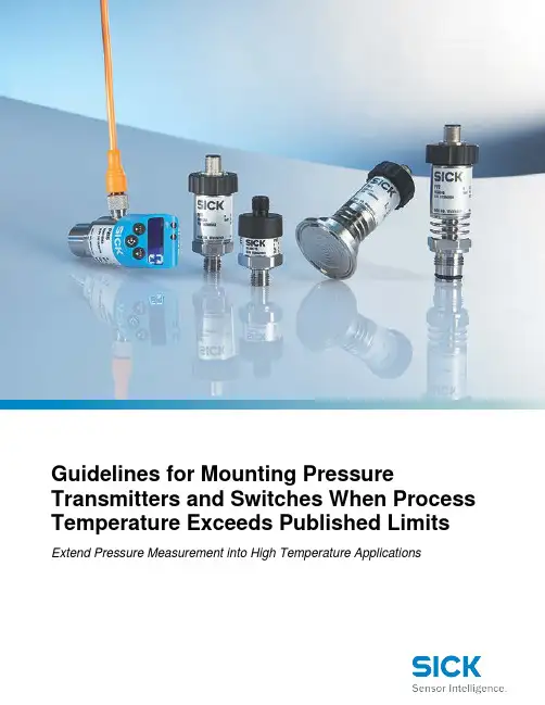
Extend Pressure Measurement into High Temperature ApplicationsIntroductionMeasurement of pressure plays a central role in many areas of a plant, in the manufacturing industry, in machine tooling, in process engineering, and in the manufacture and processing of food andbeverages. Pressure measurement in industrial applications typically occurs with the help of pressure transmitters and switches. Pressure transmitters deliver a continuous current or voltage signal proportional to the pressure applied. Pressure switches are used to monitor pressure. Electronic pressure switches are characterized by their digital switching outputs, which are activated or deactivated when the defined, programmable threshold levels have been reached.Monitoring, measuring, and controlling pressure can be tricky if the process temperature exceeds the limits of the pressure instrumentation, such as pressure transmitters and switches. It is possible to obtain an accurate pressure measurement using standard pressure transmitters in these high temperature applications. The trick is to ensure that the process is cooled before reaching the pressure measuring device.There are generally two different methods used to protect the pressure transmitter and/or the pressure switch from high temperatures. These two proven methods are done through the use of coolingelements and standoff piping. Provided below are guidelines on how to protect the pressure devices from extreme temperatures using cooling elements and standoff piping.Cooling ElementsA cooling element is an accessory that puts some distance between the transmitter and the heat of the process. There are often times “fins” that allow for air circulation for betterheat dissipation. Cooling elements are designed to cool the process to a temperature that is within the specifications of the pressure transmitter.Cooling elements are a great way to protect the transmitter from high temperature processes. Cooling elements act as a heat sink, which cools the process before it reaches the transmitter.Cooling elements can extend the maximum process temperature of pressure transmitters from 185 °F (85 °C) up to 392 °F (200 °C).Figure 1: Cooling element.Figure 2: Cooling element attached to PBS Pressure Transmitter, Switch, and Display.Cooling elements from SICK provide heat protection as shown in the tables below. For the PBS electronic pressure switch, pressure transmitter and display; cooling elements can protect within the following guidelines:Chart 1: Temperature range of PBS pressure transmitter, switch, and display when installed with a cooling element (°F).PBS maximum process temperature when installed without a cooling element is 185 °F.For the PBS electronic pressure switch, pressure transmitter and display; cooling elements can protect within the following guidelines:Chart 2: Temperature range of PBS pressure transmitter, switch, and display when installed with a cooling element (°C).PBS maximum process temperature when installed without a cooling element is 85 °C.Chart 3: Temperature range of PFT pressure transmitter when installed with a cooling element (°F).PFT maximum process temperature when installed without a cooling element is 212 °F.For the PFT pressure transmitter; cooling elements can protect within the following guidelines:Chart 4:Temperature range of PFT pressure transmitter when installed with a cooling element (°C).PFT maximum process temperature when installed without a cooling element is 100 °C.Chart 5: Temperature range of PBT pressure transmitter when installed with a cooling element (°F).PBT maximum process temperature when installed without a cooling element is 176 °F.For the PBT pressure transmitter; cooling elements can protect within the following guidelines:Chart 6: Temperature range of PBT pressure transmitter when installed with a cooling element (°C).PBT maximum process temperature when installed without a cooling element is 80 °C.If cooling elements do not provide enough cooling to meet the application, standoff piping / impulse lines may be used.Standoff PipingUsing standoff piping (otherwise known as impulse lines) cools the process before it comes in contact with the pressure transmitter. Standoff piping may also allow the user to relocate the transmitter to a more convenient location for maintenance.Impulse line lengths are calculated using a general rule of thumb. For every 100 °F that the temperature needs to drop, users need to have 1 foot of impulse lines. For instance the maximum process temperature specification of the PBS pressure transmitter, switch, and display is 185 ° F (85 °C). If the process temperature is 585 °F, the process would have to be cooled 400 °F to be within the transmitter specification (585 - 185 = 400). Where 585 is the process temperature in °F, 180 is the maximum process temperature of the PBS, and 400 is the decrease in the temperate required for the transmitter. Dropping the process temperature by 400 °F is easily done using a minimum of 4 feet of impulse lines. This is a general rule of thumb, assuming a 68 °F (20 °C) ambient temperature. For higher ambient temperatures, longer impulse lines are required. For lower ambient temperatures, shorter impulse lines are required. Also, most users add a little more pipe length for added peace of mind.If the impulse lines are too long, other problems may present themselves:•Damping of the pressure signal•Blockage of the pressure signal•Leakage at couplingsTherefore, a balance between just long enough and too long must be achieved. Piping diameters should be as follows:Type of measured fluidImpulse Line Length0-52.5 ft (0-16 m) 52.5-148 ft (16-45 m) 148-295 ft (45-90 m)Water/steam and dryair/gas0.27-0.35 in (7-9 mm) 0.4 in (10 mm) 0.51 in (13 mm) Wet air/wet gas 0.51 in (13 mm) 0.51 in (13 mm) 0.51 in (13 mm) Oils of low mediumviscosity0.51 in (13 mm) 0.75 in (19 mm) 0.98 in (25 mm) Very dirty fluids 0.98 in (25 mm) 0.98 in (25 mm) 1.50 in (38 mm)Table 1: Impulse line diameters from ISO2186:1973Type of metered fluid Impulse Line Length0-52.5 ft (0-16 m) 52.5-148 ft (16-45 m) Water/steam and dry air/gas0.27-0.35 in (7-9 mm) 0.4 in (10 mm) Wet air/wet gas 0.51 in (13 mm) 0.51 in (13 mm) Oils of low medium viscosity0.51 in (13 mm) 0.75 in (19 mm) Very dirty fluids0.98 in (25 mm)0.98 in (25 mm)Table 2: Impulse line diameters from ISO/CD 2186:2004Gas ApplicationsMount hardware upward to allow moisture to drain out and not fill the impulse piping:• Slope impulse piping at least one inch per foot(8 centimeters per meter) downward from the transmitter toward the process connection.Liquid ApplicationsMount hardware downward to allow the escape of trapped vapor in the impulse piping:• Slope impulse piping at least one inch per foot(8 centimeters per meter) upward from the transmitter toward the process connection. • Vent all gas from the liquid piping legs.• Prevent sediment deposits in the impulse piping.ConclusionThere are generally two different methods used to protect the pressure transmitter and/or the pressure switch from high temperatures. These two proven methods are cooling elements and standoff piping. Some of the time a combination of both methods is used to give the engineer added peace of mind. By using either method, a standard pressure transmitter and/or pressure switch may be used in high temperature applications.Figure 4: Mounting hardware for liquid applications.Figure 3: Mounting hardware for gas applications.。
西克SICK传感器不同的型号使用方法解析对SICK传感器本身的质量和性能有更高的要求,特别是作为用于精确测试的SICK传感器。
对于那些使用位移传感器的人来说,有必要了解位移传感器的应用方法和注意事项。
在了解SICK传感器的应用方法之前,小编首先简要介绍了SICK传感器(线性位移传感器)的主要特征参数。
SICK传感器的主要特性参数(位移传感器原理)标称电阻:电位器上指示的电阻值。
允许误差:标称电阻与实际电阻之比与标称电阻之比是电阻偏差,表示电位计的精度。
允许误差通常在±20%内得到满足,因为通常的位移传感器是通过分压施加的。
特定电阻的大小对传感器的数据采集没有影响。
线性精度:线性误差。
参数越小越好。
寿命:导电塑料位移传感器超过200万次。
重复性:参数越小越好。
分辨率:位移传感器可以反映的Zui的小位移值。
参数越小越好。
导电塑料位移传感器的分辨率极小。
如何使用SICK传感器:通常,通过使用其优异的平滑度,向SICK传感器施加电压以检测输出电压(输出电阻改变输出电压)。
小编收集并组织了线性SICK传感器和磁致伸缩位移传感器作为例子来分析位移传感器的使用。
(1)使用SICK传感器:由Minor MINOR生产的精密线性位移传感器配备了一个长连续传导轨迹型压力传感器。
它适用于控制和测量应用中的绝对位移传感,线性精度为0.05%。
它具有运动快,寿命长的特点,满足龙门精密液压机的控制要求。
根据实际要求,Kl下滑式和KTC拉杆式线性位移传感器分别安装在液压机的主缸和液压垫上。
在半自动工作过程中,液压机的主缸和液压垫分别驱动两个线性SICK传感器移动,并将收集值的两个模拟值输入到FX2N-8AD。
FX2N-8AD输入模拟输入值。
电压输入),转换为数字值并传送到PLC主机。
在工业自动化中常用的传感器介绍导语:在工业自动化中,传感器起着至关重要的作用,以使产品智能化和超自动化。
传感器帮助人们检测,分析,测量和处理各种变化在工业自动化中,传感器起着至关重要的作用,以使产品智能化和超自动化。
传感器帮助人们检测,分析,测量和处理各种变化,例如在工业生产场所发生的位置,长度,高度,外部和错位的变化。
传感器是一种设备,可以识别电气或物理或其他数量的进度,并以确认产量进度的方式交付收益。
简而言之,工业自动化传感器是输入设备,可提供有关特定物理量(输入)的输出(信号)。
传感器在预测和预防众多潜在过程中也起着举足轻重的作用,从而满足了许多工业传感应用的需求。
是自动化中使用的各种传感器:1、压力传感器压力传感器是一种可感知压力并将其转换为电信号的仪器,其数量取决于所施加的压力。
工业自动化中使用的主要压力传感器包括压力传感器和真空传感器。
压力传感器:压力传感器广泛用于工业和液压系统,这些高压工业自动化传感器也用于气候控制系统。
真空传感器:当真空压力低于大气压时,会使用真空传感器,并且很难通过机械方法进行检测。
这些传感器通常取决于电阻与温度相关的加热丝。
当真空压力增加时,对流下降,导线温度上升。
电阻成比例增加,并在压力附近进行校准,以便对真空进行有效测量。
压力传感器的应用:用于在给定位置测量低于大气压的压力;用于气象仪器,飞机,车辆和其他已实现压力功能的机械;用于系统中以测量其他变量,例如流体/气体流量,速度,水位和高度。
2、温度传感器温度传感器是一种从资源中收集有关温度的信息并将其更改为其他设备可以理解的形式的设备。
它是传感器的常用类别,可以检测温度或热量,并且可以测量介质的温度。
自动化中使用的主要温度传感器包括数字温度传感器和温湿度传感器。
数字温度传感器:数字温度传感器是基于硅的温度感应IC,可通过数字表示所测量的温度来提供准确的输出。
与涉及外部信号调理和模数转换器(ADC)的方法相比,这简化了控制系统的设计。
kistler压力传感器工作原理
Kistler压力传感器是一种能够检测压力变化的传感器,它能够将压力变化转换成电信号。
Kistler压力传感器的工作原理是把压力变化映射到一个精确的电信号上。
它的内部构成包括一个电容,一个晶体,一个小型电池,以及一些电路元件。
当压力变化时,电容内的电荷被压力变化所影响,从而使晶体的电容发生变化。
这种变化会被小型电池的电压所感受到,从而导致电路元件的状态发生变化。
当这种变化发生时,电路元件会产生一种信号,这种信号会反映出压力变化的状态,从而可以检测到压力变化。
Kistler压力传感器的优势在于高精度,它可以检测到千分之一毫米的压力变化。
它的灵敏度也非常高,它可以检测到百万分之一毫米的压力变化。
它的工作温度也很高,可以在-40°C至+200°C的温度范围内工作。
Kistler压力传感器还具有高耐久性,可以在极端环境条件下使用,耐受摩擦,振动,冲击和温度变化。
Kistler压力传感器被广泛应用于航空航天,汽车,冶金,石油和化工等行业,它能够对系统进行实时监控,提供准确可靠的压力检测数据。
Kistler压力传感器的使用不仅能够提高生产效率,而且能够提高生产质量,实现安全可靠的操作。
SICK施克传感器、SICK安全光幕、SICK激光扫描器、SICK编码器产品介绍公司代理销售产品有:日本东方马达Oriental Motor 、欧姆龙OMRON、韩国凯昆工控KACON中国销售处,和泉电气IDEC、山武AZBIL 、山洋Sanyodenki、奥托尼克斯Autonic、SMC气动元件授权为特约经销商。
特价经销日本基恩士KEYENCE 、施耐德Schneider、明纬MEANWELL 、松下电工Panasonic 、神视SUNX光电传感和三菱MITSUBISHI、PLC及变频器、小金井(KOGANEI)气动元件、韩国TPC、富士(FUJI)、安川伺服、松下伺服、DKM、住友电机、 IKO、THK直线滑动系列,多摩川(Tamagawa)等众多国际知名品牌工业自动化元件。
详细信息上海乐利自动化科技有限公司创立于2007年8月,是一家专营世界著名品牌工业自动化的公司,是从事电气自动化工程设计、施工、安装、调试,技术服务及工控组态软件的开发,提供工程设备及备件于一体的高新综合性公司。
SICK产品介绍SICK的工业用自动化传感器产品系列主要包括SICK编码器,SICK电机反馈系统,SICK定位驱动器,SICK超声波传感器,SICK电容式/电感式/电磁式接近传感器,SICK磁性气缸传感器,SICK光电开关,SICK色标传感器,SICK荧光传感器,SICK颜色传感器,SICK槽形开关,SICK测量光栅,SICK距离传感器,SICK机器视觉等。
品牌动态规格型号名称系列VMS420SICK传感器,SICK官网,德国西克,光电传感器,标识传感器,接近传感器,测量光幕Track trace systemsICR890 System SICK传感器,SICK官网,德国西克,光电传感器,标识传感器,接近传感器,测量光幕Track trace systemsM40E-052223RB0, M40S-052203AA0SICK传感器,SICK官网,德国西克,光电传感器,标识传感器,接近传感器,测量光幕Multiple light beamsafety devicesOPS Customized SICK传感器,SICK官网,德国西克,光电传感器,标识传感器,接近传感器,测量光幕Track trace systemsOPS400-00SICK传感器,SICK官网,德国西克,光电传感器,标识传感器,接近传感器,测量光幕Track trace systemsVMS510 MID SICK传感器,SICK官网,德国西克,光电传感器,标识传感器,接近传感器,测量光幕Track trace systemsM40E-052222AU0, M40S-052202AU0SICK传感器,SICK官网,德国西克,光电传感器,标识传感器,接近传感器,测量光幕Multiple light beamsafety devicesVMS410SICK传感器,SICK官网,德国西克,光电传感器,标识传感器,接近传感器,测量光幕Track trace systemsMLG0-2380P811S23SICK传感器,SICK官网,德国西克,光电传感器,标识传感器,接近传感器,测量光幕Measuring automationlight gridsVICOTEC414SICK传感器,SICK官网,德国西克,光电传感器,标识传感器,接近传感器,测量光幕Traffic senssIN30-E0407K SICK传感器,SICK官网,德国西克,光电传感器,标识传感器,接近传感器,测量光幕Inductive safetyswitchesLE20-2611SICK传感器,SICK官网,德国西克,光电传感器,标识传感器,接近传感器,测量光幕Safety relaysMKAS Multipoint SICK传感器,SICK官网,德国西克,光电传感器,标识传感器,接近传感器,测量光幕Customized analyzersystemsRE1, RE2 Non-contact safety switches - Magnetic safety switches SICK传感器,SICK官网,德国西克,光电传感器,标识传感器,接近传感器,测量光幕LiteratureFLOWSIC600 4-path SICK传感器,SICK官网,德国西克,光电传感器,标识传感器,接近传感器,测量光幕Gas flow measuringdevicesLMS511 Traffic SICK传感器,SICK官网,德国西System components克,光电传感器,标识传感器,接近传感器,测量光幕ALIS - Airpt Luggage Identification System SICK传感器,SICK官网,德国西克,光电传感器,标识传感器,接近传感器,测量光幕Track trace systemsMKAS HD SICK传感器,SICK官网,德国西克,光电传感器,标识传感器,接近传感器,测量光幕Customized analyzersystemsDWS510-ST12100SICK传感器,SICK官网,德国西克,光电传感器,标识传感器,接近传感器,测量光幕Track trace systemsC2MT-06634BBC04FE0SICK传感器,SICK官网,德国西克,光电传感器,标识传感器,接近传感器,测量光幕Safety lightcurtainsIN40-D0101K SICK传感器,SICK官网,德国西克,光电传感器,标识传感器,接近传感器,测量光幕Inductive safetyswitchesDME3000-111SICK传感器,SICK官网,德国西克,光电传感器,标识传感器,接近传感器,测量光幕Long range distancesenssVMS520 Ster SICK传感器,SICK官网,德国西克,光电传感器,标识传感器,接近传感器,测量光幕Track trace systemsGL10G-N1252SICK传感器,SICK官网,德国西克,光电传感器,标识传感器,接近传感器,测量光幕Photoelectric senssC2MT-07214BBC03FB0SICK传感器,SICK官网,德国西克,光电传感器,标识传感器,接近传感器,测量光幕Safety lightcurtainsAOS501SICK传感器,SICK官网,德国西克,光电传感器,标识传感器,接近传感器,测量光幕Object detectionsystemsRFMS Pro SICK传感器,SICK官网,德国西克,光电传感器,标识传感器,接近传感器,测量光幕Track trace systemsMLG0-2050F812S25SICK传感器,SICK官网,德国西克,光电传感器,标识传感器,接近传感器,测量光幕Measuring automationlight gridsUE43-2MF3D2SICK传感器,SICK官网,德国西克,光电传感器,标识传感器,接近传感器,测量光幕Safety relaysRE13-DAP SICK传感器,SICK官网,德国西克,光电传感器,标识传感器,接Magnetic safetyswitches近传感器,测量光幕AOS104 RTG SICK 传感器,SICK 官网,德国西克,光电传感器,标识传感器,接近传感器,测量光幕Object detection systems C2MT-06634BBC03FB0 SICK 传感器,SICK 官网,德国西克,光电传感器,标识传感器,接近传感器,测量光幕Safety light curtains MKAS Compact SICK 传感器,SICK 官网,德国西克,光电传感器,标识传感器,接近传感器,测量光幕Customized analyzer systems RE13-SA05 SICK 传感器,SICK 官网,德国西克,光电传感器,标识传感器,接近传感器,测量光幕Magnetic safety switches ICR880 System SICK 传感器,SICK 官网,德国西克,光电传感器,标识传感器,接近传感器,测量光幕Track trace systemsIN40-D0202K SICK 传感器,SICK 官网,德国西克,光电传感器,标识传感器,接近传感器,测量光幕Inductive safety switches C2MT-06634BBC03FE0 SICK 传感器,SICK 官网,德国西克,光电传感器,标识传感器,接近传感器,测量光幕Safety light curtainsVICOTEC450 SICK 传感器,SICK 官网,德国西克,光电传感器,标识传感器,接近传感器,测量光幕Traffic senssUpgrade Safexpert Risk Assessment to Compact full version SICK 传感器,SICK 官网,德国西克,光电传感器,标识传感器,接近传感器,测量光幕Safety software Safexpert DWS Dynamic (Dimensioning weighing scanning system) SICK 传感器,SICK 官网,德国西克,光电传感器,标识传感器,接近传感器,测量光幕Track trace systems AOS502 SICK 传感器,SICK 官网,德国西克,光电传感器,标识传感器,接近传感器,测量光幕Object detection systems VISIC620-1111 SICK 传感器,SICK 官网,德国西克,光电传感器,标识传感器,接近传感器,测量光幕Traffic senssVMS520 OEM SICK 传感器,SICK 官网,德国西克,光电传感器,标识传感器,接近传感器,测量光幕Track trace systemsOPS400-60 SICK 传感器,SICK 官网,德国西克,光电传感器,标识传感器,接近传感器,测量光幕 Track trace systemsUE410-XU3T5SICK传感器,SICK官网,德国西克,光电传感器,标识传感器,接近传感器,测量光幕Safety controllersGL10G-N1251SICK传感器,SICK官网,德国西克,光电传感器,标识传感器,接近传感器,测量光幕Photoelectric senssRE23-SA84SICK传感器,SICK官网,德国西克,光电传感器,标识传感器,接近传感器,测量光幕Magnetic safetyswitchesIN30-E0306K SICK传感器,SICK官网,德国西克,光电传感器,标识传感器,接近传感器,测量光幕Inductive safetyswitchesUE42-2HD3D2SICK传感器,SICK官网,德国西克,光电传感器,标识传感器,接近传感器,测量光幕Safety relaysG10 Small photoelectric senss (zh)SICK传感器,SICK官网,德国西克,光电传感器,标识传感器,接近传感器,测量光幕Literature。