英文科技文献及翻译
- 格式:doc
- 大小:209.00 KB
- 文档页数:14

科技文献中英文摘要范文English:Nowadays, with the rapid advancement of technology, there has been increasing interest in applying artificial intelligence (AI) to various fields such as healthcare, finance, transportation, and more. AI has the potential to revolutionize these industries by improving efficiency, accuracy, and decision-making processes. In healthcare, AI tools can assist doctors in diagnosing diseases, predicting patient outcomes, and even personalizing treatment plans. In finance, AI algorithms can analyze market trends, predict stock prices, and detect fraudulent activities. In transportation, AI can optimize routes, reduce traffic congestion, and improve safety measures. Despite the great benefits AI can bring, there are also ethical and privacy concerns that need to be addressed. It is essential for policymakers, researchers, and industry professionals to work together to ensure responsible and ethical AI development.中文翻译:如今,随着科技的快速发展,人们越来越热衷于将人工智能(AI)应用于医疗保健、金融、交通等各个领域。

Sensing Human Activity:GPS Tracking感应人类活动:GPS跟踪Stefan van der Spek1,*,Jeroen van Schaick1,Peter de Bois1,2and Remco de Haan1Abstract:The enhancement of GPS technology enables the use of GPS devices not only as navigation and orientation tools,but also as instruments used to capture travelled routes:assensors that measure activity on a city scale or the regional scale.TU Delft developed aprocess and database architecture for collecting data on pedestrian movement in threeEuropean city centres,Norwich,Rouen and Koblenz,and in another experiment forcollecting activity data of13families in Almere(The Netherlands)for one week.Thequestion posed in this paper is:what is the value of GPS as‘sensor technology’measuringactivities of people?The conclusion is that GPS offers a widely useable instrument tocollect invaluable spatial-temporal data on different scales and in different settings addingnew layers of knowledge to urban studies,but the use of GPS-technology and deploymentof GPS-devices still offers significant challenges for future research.摘要:增强GPS技术支持使用GPS设备不仅作为导航和定位工具,但也为仪器用来捕捉旅行路线:作为传感器,测量活动在一个城市或区域范围内规模。
Original articleTextile Research Journal Thermal and mechanical properties82(2) 195–202 Reprints and permissions:! The Author(s) 2011of ultrasonically treated wool/journalsPermissions.nav DOI: 10.1177/0040517511426493Qing Li 1, Christopher J Hurren 1, Hengxing Yu 2,Cailing Ding 2 and Xungai Wang 1,3AbstractWool fabrics, ultrasonically treated in various chemical conditions and for different time durations, were analysed for thermal properties by thermo-gravimetric analysis and differential scanning calorimeter, in comparison with the untreated fabric. Fabric mechanical properties, such as bending and tensile performance, and changes in fibre morphology were also evaluated before and after ultrasonic treatment.It is found that wool treated with ultrasonics at the appropriate time, has less mass loss and a higher thermal degradation temperature than that without ultrasonic treatment or with prolonged ultrasonic treatment. Resistance to thermal degradation is reduced when wool is ultrasonically treated in the presence of alkali. Differential scanning calorimeter analysis shows that while ultrasonic treatment has little effect on fibre crystallinity, an appropriate treatment can provide wool with increased water absorption. Ultrasonic treatment stiffens wool fabric to some extent when the treatment time is prolonged. The addition of detergent alone to the ultrasonic bath has little effect on fabric tensile behaviour, whereas a treatment with both detergent and alkali produces severe fibre damage and significant loss of fabric tensile strength.KeywordsWool fabric, ultrasonics, thermal properties, TGA, DSC, mechanical propertiesIntroductionThe adoption of ultrasonics on textiles has potential in energy saving, product quality improvement and a reduction of auxiliary chemical use andprocessing time.1,2Recent studies have demonstrated some positive results in ultrasonic wool wet processing where the con-ventional process consumes a large amount of water and energy. It has been shown that effective stainremoval can be achieved with the assistance of the ultrasonics.3–6Wool scoured with ultrasonics has less fibre felting hence the subsequent topmaking process and product yield can be improved.7Studies on wool dyeing demon-strated that with the assistance of ultrasonics, a better fibre dye uptake can be achieved with a variety of dyes in a shorter dyeing time periodand at a lower tempera-ture.8–10McNeil and McCall reported that ultrasound pre-tr eatment can increase the effectiveness of subse -quentoxidative-reductive bleaching of wool.11Acoustic cavitation, known as the process of bubble formation and collapse, is considered responsible for most of ultrasound ’s physical and chemical effectsobserved in solid/liquid or liquid/liquid systems.13During cavitation,bubble collapse produces intense local heating with temperatures of up to 5000 C, high pressures of about 1000 atm, and very short lifetimes withheating and cooling rates above 1010 K/s.14These transient, localized hot spots drive high-energy chemical reactions.Ultrasonic waves are vibrations with frequency above 20 kHz and require a medium with elastic prop-erties for propagation. Wet textile processing involves transport of solid/liquid substances across the fibres1Centre for Material and Fibre Innovation, Deakin University,Australia. 2Shandong Ruyi Technology Group, Jining, China. 3School of Textile Science and Engineering, Wuhan Textile University, China.Corresponding author:Xungai Wang, Centre for Material and Fibre Innovation, Deakin University, Geelong, Victoria 3217, AustraliaEmail: xwang@.au196Textile Research Journal 82(2)with water as the medium. Therefore mass transfer in the inter- and intra-fibre pores is the basic phenomenon in textile wet finishing.12 In the last 50 years, much work has been aimed at understanding and controlling mass transfer within the processing bath to provide the energy to enhance chemical interactions. Little has been reported on how ultrasonic treatment affects the prop-erties of wool fabrics.Wool is composed mainly of the protein a-keratin, which is a crystalline polypeptide with adjacent poly-peptide chains crosslinked with disulphide bonds from the amino acid cystine. These crosslinks make keratin relatively hard and insoluble.15Wool cortical cells are held together by the cell membrane complex (CMC), which also separates cortical cells from those of the cuti-cle. Because the CMC is only slightly crosslinked, it is more susceptible to chemical attack than other regions of the fibre, especially if strongly alkaline conditions or very high temperatures are used during fabric manufacturing processes.16It is revealed in a recent study that while wool crys-tallinity remains unaffected, protein chains can be rear-ranged in a more regular and less flexible manner, as a result of ultrasonic treatment, which can lead to an increase in fabric tenacity and a reduction in fabric extensibility.17 Textile wet processing is generally con-ducted with the assistance of chemicals and heat. During the process, textiles are exposed to a rather com-plicated condition, with fibres and fabrics being subject to a variety of physical and chemical reactions that are necessary for the treatment. Issues such as temperature, pH, chemical concentration, and treatment time are crit-ical in affecting the processing outcomes and subsequent fabric properties.The aim of this work is to gain further insights into ultrasound induced property changes of wool fabrics. Thermo-gravimetric analysis (TGA) and differential scanning calorimetry (DSC) were used to investigate changes in wool thermal properties, which can be attrib-uted to the modifications of micro structure of the fibre. Fabric mechanical properties, such as bending and ten-sile performance, were measured under various ultra-sonic treatment conditions. Wool morphology, before and after ultrasonic treatment, were examined using SEM.In this work, measurements were conducted on fab-rics that were ultrasonically treated in various condi-tions and at different pHs, similar to those used in industry. The outcome of this study is expected to provide implications to the wool wet processing, espe-cially to the wool scouring industry, where the ultra-sonic technology is considered to replace the traditional process to enable a green and friendly working environment.ExperimentalSample preparationsLoomstate, undyed, plain-weave pure wool fabric sample taken from ordinary mill production was used in this work, fabric weight 140 g/m2, ends and picks 27 23/cm. Before treatment, fabric samples were wet-relaxed in water at room temperature for 24 hours.In this work, fabric soaked in water at 50 C for 1 hour was used as a control. Hydropol TN450 (nonyl phenol ethoxylate detergent, Huntsman Chemical) was used as the washing detergent. Sodium carbonate(Na2CO3), which is commonly used as the builder in wool scouring industry, was used in the work.3,18 Fabric treatment conditions are shown in Table 1.Ultrasonic treatmentUltrasonic treatment was conducted using a KQ-300VDE 10 litre ultrasonic bath (Kunshan Ultrasonic Instrument Co. Ltd., China). The bath frequency was capable of irradiating at two frequencies (45/80 kHz) with frequency sweeping. In this work, a fixed frequency of 45 kHz with frequency sweeping turned off, was used for all experiments. Power was set at a maximum of 300 W for all experiments. For the fabrics to receive homogeneous irradiation, each sample was placed hor-izontally in the bath around 5 cm from the bottom in each treatment.19The samples were clamped unstrained to minimize the possibility of permanent set beingTable 1. Fabric treatment conditionsDeionized HydrpolTN450 Na2CO3water, at 50 C Ultrasonics (0.5 g/L) (0.2 g/L) pHcontrol sample 7.01 U-treated in water 7.01 U-treated with detergent 7.07 U-treated with detergent and alkali 8.78Li et al. 197introduced into the fabrics. Ultrasonic processing times of 1 hour and 2 hours were applied in this work.Thermo-gravimetric analysis (TGA)TGA curves were obtained with a NETZSH STA409PC instrument (NETZSH Gerateba¨u GmbH, Germany). Alumina crucibles were used to hold 5–10 mg of wool snippets for measurements. Nitrogen gas was employed for purging samples at 30 mL/min and for protection at 10 mL/min. The starting temperature was 30 C, and final temperature 350 C. Temperature was increased at a heating rate of 10 C/min. At least five measure-ments were conducted for each sample.Differential scanning calorimetry (DSC) Measurements were conducted with a TA Q200 thermal analysis instrument (TA Instruments, US). Micro-punched aluminium crucibles of 40 m L were used to hold 3–5 mg of wool snippets. Measurement conditions: starting temperature, 30 C; final temperature, 280 C; heating rate, 10 C/min; purging gas nitrogen, 50 mL/ min. At least five measurements were conducted for each sample.Water absorption measurementWater absorption of fabric was expressed as the percent-age change in weight of the sample at standard condi-tions (W c), relative to the fabric dry weight (W d).¼ W d ðÞð Þ Water absorption W c W d 100 % 1Weights of conditioned fabrics were measured after the samples had been conditioned at 20 2 C and 65 2% relative humidity for at least 24 hours. Drying of the fabric was carried out in an oven at 105 C for 60 minutes. Samples were weighed immedi-ately after being taken out of the oven. Measurement of fabric thicknessFabric thickness under 0.5 kPa was measured according to AS2001.2.15-1989 using a MESDAN LAB Thickness Tester DGTW01B. At least 10 measurements were car-ried out for each fabric sample and results were averaged.Measurement of fabric bending rigidityFabric mechanical properties were measured according to BSI BS 3356-1991 determination of bending length and flexural rigidity of fabrics (AMD 6337), using a SDL ATLAS Textile Solutions Fabric Stiffness Tester. Bending lengths of three separate warp and weft sam-ples were measured. The bending rigidity (B) in m N m was given by:B ¼ W C39:81106ð2Þ where W is the fabric mass per unit area in g/cm2, and C is the bending length in mm. All tests were conducted under standard conditions of 20 2 C and 65 2% rel-ative humidity.SEM analysisFibre surface morphology was examined using a Zeiss Supra 55 VP field emission gun scanning electron micro-scope. Measurements were conducted with an EHT of 5 kV, a working distance (WD) of 7.4 mm and an aper-ture size of 30 m m.Tensile testFabric samples, approximately 25 mm wide and 100 mm long, were cut in the warp and weft directions. The sam-ples were trimmed so that before testing each sample contained a fixed number of ends or picks in the mea-surement direction. At least three separate samples in each direction were measured in each case, and the results of measurements in the warp and weft directions were averaged. The standard deviation was calculated in each case.A Lloyd LR 30K (Lloyd, UK) tensile tester was used to measure fabric extension, expressed as a percentage of the original length. A gauge length of 60 mm was set in the test. The extension speed was 10 mm/min. Dry fabric tests were conducted under standard conditions of 20 2 C and 65 2% relative humidity. For wet fabric measurement, samples were wet-relaxed by soak-ing in water for 2 hours before being passed through a pad mangle, the pressure of which was adjusted to make the water content (pickup) equal to 100%. The tensile properties of the fabric samples were measured immedi-ately after padding.Results and discussionThermal analysisTGA. Figure 1 shows TGA curves of the wool samples with and without ultrasonic treatment. Two phases of mass loss with increasing temperature were caused by moisture evaporation (at around 55 C) and thermal decomposition of the fibres (at around 230 C).198Textile Research Journal 82(2)The associated onset temperatures and ratios of mass change of samples obtained from TGA curves are shown in Table 2.Onset temperatures, at which the water evaporation and thermal degradation of the keratin occurred, are observed to be delayed on the sample ultrasonically treated for 1 h, as shown in Table 2. The higher onset temperatures are also accompanied by relatively lower levels of mass loss of the sample when temperature increases. This is not unexpected as protein chains in the macrofibrils can be rearranged to a more regular structure as aresult of ultrasonic treatment at an appro-priate length of time.17A stronger and more stable fibre structure contributes to fibre thermal degradation at a higher temperature. The effect of treatment with deter -gent and alkali on the TG behaviour of the fabric is not evident in this work.DSC. DSC curves of the samples, shown in Figure 2, provide information of three processing stages that are typical features for keratin protein. It is seen that vari-ation in DSC curves of the sample from different treat -ments mainly occurred at the glass transition and water evaporation process. Glass transition temperature (Tg ) for wool is between 40 C and 60 C. In practice however, because of the complex structure of wool protein, the 105100 Water evaporation95Thermal90decomposition(%)M a s s858075Without ultrasonics (control)Ultrasonic treated for 1h70 Ultrasonic treated for 2h6550100150200250300Temperature (°C)Figure 1. TGA curves for wool with and withoutultrasonic treatment.glass transition occurs over a temperature range rather than at a singletemperature.15This temperature range is generally overlapped with the beginning of the peak cor-responding to the water evaporation in a DSC curve.20Characterization of the DSC curves for each of the samples tested is shown in Table 3. Moisture evapora-tion peak temperature, Tw , of around90 C was mea-sured in this work. For fabric treated in water, both the evaporation temperature, Tw , and water evaporation enthalpy, D Hw , are higher on the ultrasonically treated wool (1 h) than that without ultrasonic treatment (con-trol sample) and prolonged ultrasonic treated (2 h). Water evaporation enthalpy in DSC is directly related to the amount of water within the fibres. This obser-vation confirms the results on an increased water absorption by the ultrasonically treated wool (1 h) shown in Figure 3,which is due to the removal of fibre internal lipids.17In each treatment, alower water evaporation enthalpy is seen on the sample treated for2 h, than that treated for 1 h.When ultrasonic treatment was accompanied by detergent and alkali, significantly lowered values of D Hw are seen when compared with their counterparts. This is expected as the alkali is known to be able to attack the wool fibre matrix where most of the hydro-philic residues reside.The second endothermic heat transfer occurred at the peak of around 232 C in the DSC curves. This is known as the denaturation enthalpy which is related to the amount of helical protein in the fibres, and corresponds to the wool thermal decomposition shown previously in the TGA curves. Measurement of enthalpy of protein denaturation enables the determinationof fibre crystal-linity.21,22The overlapped denaturation enthalpy peaks in DSC curves seen in Figure 2 suggest there is no sig-nificant change in fibre crystallinity. This observation is in agreement with the results shown in aprevious study 17where crystallinity of ultrasonically treated wool was measured by XRD.The denaturation temperature is controlled by the nature of the fibreamorphous matrix.23In this work, little difference is seen in the denaturation temperature Td for most of the sample tested. The slightly lowered temperature for the sample with prolonged ultrasonic treatment in the presence of detergent and alkali couldTable 2. Onset temperatures and mass loss of wool with and without ultrasonic treatmentWater evaporationThermal decompositionSample IDOnset temp ( C) Mass loss at 50–150 C (%) Onset temp ( C) Mass loss at 150–300 C (%) control sample54.6 8.26 229.2 20.06 U-treated in water, 1 h 56.8 7.48 231.8 19.49 U-treated in water, 2 h55.58.12230.519.92Li et al.199be due to the reduction of the wool cystine content. Breakage of disulphide bonds caused changes of cystine in the fibre matrix region, as a result of the alkali attack which was accelerated by heat and pressure generated from ultrasonics. Slightly lowered denaturation temper-ature suggests less resistance to thermal degradation of the sample.Fabric mechanical propertiesMeasurement results of fabric bend-ing rigidity are shown in Figure 4. Significantly lower values of bending rigidity are seen for the fabric ultra-sonically treated for 1 h, than that without treatment (control sample) and with prolonged treatment (2 h). Wool bending modulus has been shown to be inverselyproportional to the fibre moisture content.24The drop of bending rigidity for ultrasonic treated wool (1 h) may be attributed to its increased moistureabsorption dem-onstrated in the DSC analysis and in the previous study.17The observed increased level of fabric bending rigid-ity when the ultrasonic treatment time was extended to 2 h can also be understood by the changes in fibre macrostructure due to the ultrasonic treatment. While the crystalline regionsprovide the fibres with strength, in the amorphous regions, relatively fewer bonds between the polymer chains and the random distribution of the chains are believed to be responsible for the elasticity and flexibility of thefibre.15Because there are fewer bonds between the polymer chains in the matrix region, the protein molecules can be actively involved in the ultrasonic treatment process and rearrange them-selves. A regular distribution of protein chains is thus expected to form from the previous random one, leading to an increased fibre bending resistance.The observed fabric bending performance is further confirmed by the testing results of fabric thickness under 0.5 kPa pressure, shown in Figure 5. While there is little difference between the control sample and the fabric ultrasonically treated for 1 h, an increased value of fabric thickness is observed on the fabric that had undergone prolonged ultrasonic treatment. The stiffness of a fabric in bending is very dependent on its thick -ness, thethicker the fabric the stiffer it is, if all other factors remain the same.25When fabric is subjected to surface compression, as it is during the measurement,0 Glass transitionα–keratin denaturation(m W )–2Water evaporationf l o w(Td, D Hd)H e a t–4Without ultrasonics(Tw, D Hw)Ultrasonic treated for 1hUltrasonic treated for 2h–650100150 200250Temperature (°C)Figure 2. DSC curves for wool with and without ultrasonic treatment.1614(%)a b s o r p t i o n 1210W a t e r 86WithoutUltrasonic Ultrasonicultrasonicstreated for 1htreated for 2hFigure 3. Water absorption of wool with and without ultra-sonic treatment.Table 3. DSC values of wool under various ultrasonic treatment conditionsSample IDTw ( C) Hw ( J/g) Td ( C) Hd ( J/g) control sample90.73 216.7 232.89 11.59 U-treated in water, 1 h 95.78 221.1 232.72 11.60 U-treated in water, 2 h89.22 209.3 232.44 11.50 U-treated with detergent, 1 h 94.26 216.5 232.65 12.69 U-treated with detergent, 2 h83.20 187.8 232.36 10.79 U-treated with detergent and alkali, 1 h 82.89 202.9 232.42 13.13 U-treated with detergent and alkali, 2 h83.64175.2232.0111.93Bending rigidity.。
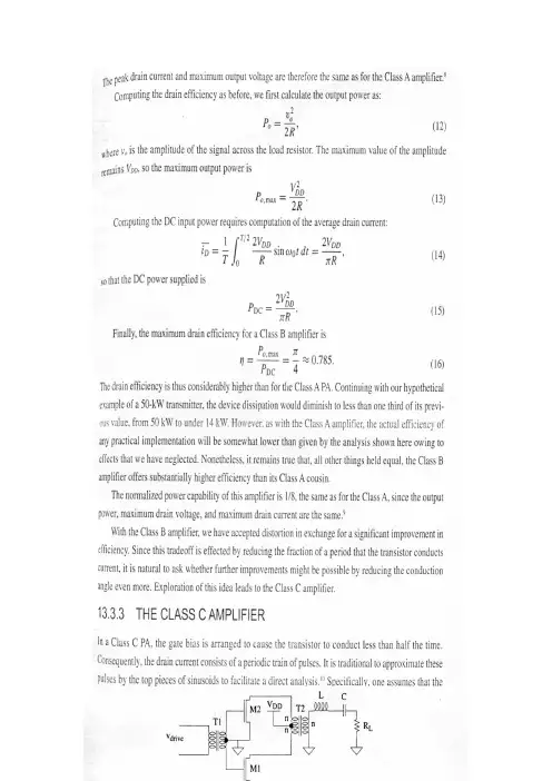
13.3.3 C类放大器在C类功率放大器中,栅的偏压设成使晶体管在小于一半的时间内导通。
因此,漏极电流是由周期性的一串脉冲构成的。
传统上用正弦的上面部分来近似这些脉冲以便于进行直接分析②。
特别是我们假设漏极电流具有如下的形式:式中,偏置值I DC类似于线性放大器中的偏置电流,它对于C类放大器实际上是负值。
自然,整个漏极电流i D心总是为正或为零。
也就是说,漏极电流在晶体管导通时是一段正弦波,而在晶体管截止时为零。
我们继续假设晶体管在任何时候的工作情况都像是一个电流源(高输出阻抗)③。
由于我们仍然有一个高Q值的输出振荡回路,所以在负载两端的电压基本上保持为正弦,因此漏极电压和漏极电流如图13.4所示。
在以下的推导中,不必担心能否重复所有的这些细节。
正如我们将要看到的,我们如何设计这样的放大器与这些公式本身的含义有显著的不同,所以重点要放在所得到的一般结论而不是一些具体细节上。
我们从求解漏极电流不为零时总的导通角开始。
为了简化得到这一答案所需要的步骤,我们首先用余弦而不是正弦来重新写出漏极电流的表达式:显然,这样做没有任何改变,因为时间原点总是任选的。
在经过这样的修改之后,电流脉冲就如图13.5所示。
使电流等于零并求出总的导通角2中得到:我们现在可以计算平均漏极电流为:在用I DC的表达式替换后得到:我们将很快用这个表达式来推导效率作为导通角函数的公式。
我们需要的另一个量是传送到负载的功率的一般表达式。
正如与B类放大器一样由于高Q值的振荡回路而被简化,所以我们只需要计算傅里叶级数中的基波项:利用我们通过负载的基波电流的表达式,我们可以很容易地推导出最大输出电压摆幅的公式:上式允许我们求解用V DD表示的电流irf:峰值漏极电流为irf与偏置项的和为:上式可简化为:对于固定的输出电压,当脉冲宽度减小至零时,峰值漏极电流接近无穷大。
利用我们刚刚推导的公式可以很容易地计算出漏极效率为:当导通角缩小至零时,效率接近100%。
附录附录A 英语科技文献Manual Transmission BasicsIt's no secret that cars with manual transmissions are usually more fun to drive than their automatic-equipped counterparts. If you have even a passing interest in the act of driving, then chances are you also appreciate a fine-shifting manual gearbox. But how does a manual trans actually work? With our primer on automatics(or slushboxes, as detractors call them) available for your perusal, we thought it would be a good idea to provide a companion overview on manual trannies, too.A brief history lesson shows that manual transmissions preceded automatics by several decades. In fact, up until General Motors offered an automatic in 1938, all cars were of the shift-it-yourself variety. While it's logical for many types of today's vehicles to be equipped with an automatic -- such as a full-size sedan, SUV or pickup -- the fact remains that nothing is more of a thrill to drive than a tautly suspended sport sedan, sport coupe or two-seater equipped with a precise-shifting five- or six-speed gearbox. It's what makes cars such as a Corvette, Mustang, Miata or any BMW sedan or coupe some of the most fun-to-drive cars available today.We know which types of cars have manual trannies. Now let's take a look at how they work. From the most basic four-speed manual in a car from the '60s to the most high-tech six-speed in a car of today, the principles of a manual gearbox are the same. The driver must shift from gear to gear. Normally, a manual transmission bolts to a clutch housing (or bell housing) that, in turn, bolts to the back of the engine. If the vehicle has front-wheel drive, the transmission still attaches to the engine in a similar fashion but is usually referred to as a transaxle. This is because the transmission, differential and drive axles are one complete unit. In a front-wheel-drive car, the transmission also serves as part of the front axle for the front wheels. In the remaining text, a transmission and transaxle will both be referred to using the term transmission.The function of any transmission is transferring engine power to the driveshaft and rear wheels (or axle halfshafts and front wheels in a front-wheel-drive vehicle). Gears inside the transmission change the vehicle's drive-wheel speed and torque in relation to engine speed and torque. Lower (numerically higher) gear ratios serve as torque multipliers and help the engine to develop enough power to accelerate from a standstill.Initially, power and torque from the engine comes into the front of the transmission and rotates the main drive gear (or input shaft), which meshes with the cluster or counter shaft gear -- a series of gears forged into one piece that resembles a cluster of gears. The cluster-gear assembly rotates any time the clutch is engaged to a running engine, whether or not the transmission is in gear or in neutral.There are two basic types of manual transmissions. The sliding-gear type and the constant-mesh design. With the basic -- and now obsolete -- sliding-gear type, nothing is turning inside the transmission case except the main drive gear and cluster gear when the trans is in neutral. In order to mesh the gears and apply engine power to move the vehicle, the driver presses the clutch pedal and moves the shifter handle, which in turn moves the shift linkage and forks to slide a gear along the mainshaft, which is mounted directly above the cluster. Once the gears are meshed, the clutch pedal is released and the engine's power is sent to the drive wheels. There can be several gears on the mainshaft of different diameters and tooth counts, and the transmission shift linkage is designed so the driver has to unmesh one gear before being able to mesh another. With these older transmissions, gear clash is a problem because the gears are all rotating at different speeds.All modern transmissions are of the constant-mesh type, which still uses a similar gear arrangement as the sliding-gear type. However, all the mainshaft gears are in constant mesh with the cluster gears. This is possible because the gears on the mainshaft are not splined to the shaft, but are free to rotate on it. With a constant-mesh gearbox, the main drive gear, cluster gear and all the mainshaft gears are always turning, even when the transmission is in neutral.Alongside each gear on the mainshaft is a dog clutch, with a hub that's positively splined to the shaft and an outer ring that can slide over against each gear. Both the mainshaft gear and the ring of the dog clutch have a row of teeth. Moving the shift linkagemoves the dog clutch against the adjacent mainshaft gear, causing the teeth to interlock and solidly lock the gear to the mainshaft.To prevent gears from grinding or clashing during engagement, a constant-mesh, fully "synchronized" manual transmission is equipped with synchronizers. A synchronizer typically consists of an inner-splined hub, an outer sleeve, shifter plates, lock rings (or springs) and blocking rings. The hub is splined onto the mainshaft between a pair of main drive gears. Held in place by the lock rings, the shifter plates position the sleeve over the hub while also holding the floating blocking rings in proper alignment.That's the basics on the inner workings of a manual transmission. As for advances, they have been extensive over the years, mainly in the area of additional gears. Back in the '60s, four-speeds were common in American and European performance cars. Most of these transmissions had 1:1 final-drive ratios with no overdrives. Today, overdriven five-speeds are standard on practically all passenger cars available with a manual gearbox.Overdrive is an arrangement of gearing that provides more revolutions of the driven shaft (the driveshaft going to the wheels) than the driving shaft (crankshaft of the engine). For example, a transmission with a fourth-gear ratio of 1:1 and a fifth-gear ratio of 0.70:1 will reduce engine rpm by 30 percent, while the vehicle maintains the same road speed. Thus, fuel efficiency will improve and engine wear will be notably reduced. Today, six-speed transmissions are becoming more and more common. One of the first cars sold in America with a six-speed was the '89 Corvette. Designed by Chevrolet and Zahnradfabrik Friedrichshafen (ZF) and built by ZF in Germany, this tough-as-nails six-speed was available in the Corvette up to the conclusion of the '96 model year. Today, the Corvette uses a Tremec T56 six-speed mounted at the back of the car.Many cars are available today with six-speeds, including the Mazda Miata, Porsche Boxster S and 911, Dodge Viper, Mercedes-Benz SLK350, Honda S2000, BMW 3-Series and many others. Some of these gearboxes provide radical 50-percent (0.50:1) sixth-gear overdrives such as in the Viper and Corvette, while others provide tightly spaced gear ratios like in the S2000 and Miata for spirited backroad performance driving. While the bigger cars mentioned above such as the Viper and Vette often have two overdrive ratios (fifth and sixth) the smaller cars like the Celica and S2000 usually have one overdriven gear ratio (sixth) and fifth is 1:1.Clearly a slick-shifting manual transmission is one of the main components in a fun-to-drive car, along with a powerful engine, confidence-inspiring suspension and competent brakes. For more information on a manual transmission's primary partner component, check out our basic primer on clutches and clutch operation.附录B 文献翻译手动变速器基础汽车手动变速器相比于自动变速器的驾驶装备来说,在驾驶方面拥有更多的乐趣,这已不再是什么秘密了。
科技文献翻译Technology has transformed every aspect of our lives, from the way we communicate and work to how we shop and entertain ourselves. With the rapid advancement of technology, there is a growing demand for accurate translations of technology-related literature. This article aims to provide a translation of a technology paper consisting of 700 words.The paper titled "The Role of Artificial Intelligence in Autonomous Vehicles" explores the impact of AI in self-driving cars. Autonomous vehicles have gained significant attention in recent years due to their potential to revolutionize transportation. This paper discusses how AI technologies, such as deep learning and machine vision, have contributed to the development of autonomous vehicles.一项名为“人工智能在自动驾驶汽车中的角色”的研究探讨了AI在无人驾驶汽车中的影响。
在过去几年中,由于其改变出行方式的潜力,自动驾驶汽车引起了广泛关注。

目录1 天线的性能 (1)1.1天线辐射 (2)1.2增益 (3)1.3有效面积 (6)1.4路径损耗 (6)1.5雷达距离方程和截面 (8)1.6为什么要使用一个天线? (10)2 PROPERTIES OF ANTENNAS (11)2.1 ANTENNA RADIATION (12)2.2GAIN (14)2.3EFFECTIVE AREA (17)2.4PATH LOSS (17)2.5RADAR RANGE EQUATION AND CROSS SECTION (19)2.6WHY USE AN ANTENNA? (22)1 天线的性能一个方法是一本有关天线的书是从讨论天线如何辐射开始的。
从麦克斯韦方程组,我们得出了电磁波。
之后,进行冗长的讨论,其中包含了很多数学,我们在讨论这些波如何在导体上激发电流。
这个情节的下半部分,就是电流的辐射和产生的电磁波。
你可能已经研究过这个问题,或如果你想增进你的阅历,参考在电磁学方面的书籍。
研究电磁学就有了一些数学方面的见识来描述天线的辐射,并提供严谨,以防止错误。
我们跳过讨论这些方程,直接转到实际的问题。
这是很重要的认识到,天线在电流中产生辐射。
设计构成的控制电流产生预期的辐射分布,其所谓的方向图。
在许多情况下,问题是如何防止电流中的辐射,如在集成电路。
每当一电流变为在距离上从其返回电流中分隔,它发热着。
简单地说,我们的设计就是为了保持两个电流靠近在一起,以减少辐射。
一些讨论会忽略电流的分布,而作为代替则会考虑得出的数量,如在各个领域的光圈或磁流在一个缝隙或靠近边缘的一微带斑纹。
你会发现我们使用任何的概念来提供深入的或简化的数学。
天线1转换电路领域,必将成为传播的电磁波,并通过互惠,从通过电磁波中收集动力。
麦克斯韦方程组预测,任何时间变电气或磁场产生相反的领域和形成一电磁波。
波有其两个领域的面向正交,而且它在正常的方向上传播给由垂直的电场和磁场所定的飞机。
附录附录A英文科技文献Transmission OverviewTransmission gearbox's function the engine's output rotational speed is high, the maximum work rate and the maximum torque appears in certain rotational speed area. In order to display engine's optimum performance, must have a set of variable speed gear, is coordinated the engine the rotational speed and wheel's actual moving velocity. The transmission gearbox may in the automobile travel process, has the different gear ratio between the engine and the wheel, through shifts gears may cause the engine work under its best power performance condition. Transmission gearbox's trend of development is more and more complex, the automaticity is also getting higher and higher, the automatic transmission will be future mainstream.Automotive Transmission's mission is to transfer power, and in the process of dynamic change in the transmission gear ratio in order to adjust or change the characteristics of the engine, at the same time through the transmission to adapt to different driving requirements. This shows that the transmission lines in the automotive transmission plays a crucial role. With the rapid development of science and technology, people's car is getting higher and higher performance requirements, vehicle performance, life, energy consumption, such as vibration and noise transmission depends largely on the performance, it is necessary to attach importance to the study of transmission.Transmission gearbox's pattern the automobile automatic transmission common to have three patterns: Respectively is hydraulic automatic transmission gearbox (AT), machinery stepless automatic transmission (CVT), electrically controlled machinery automatic transmission (AMT). At present what applies is most widespread is, AT becomes automatic transmission's pronoun nearly.AT is by the fluid strength torque converter, the planet gear and the hydraulic control system is composed, combines the way through the fluid strength transmission and the gear to realize the speed change bending moment. And the fluid strength torque converter is the most important part, it by components and so on pump pulley,turbine wheel and guide pulley is composed, has at the same time the transmission torque and the meeting and parting function.And AT compare, CVT has omitted complex and the unwieldy gear combination variable transmission, but is two groups of band pulleys carries on the variable transmission. Through changes the driving gear and the driven wheel transmission belt's contact radius carries on the speed change. Because has cancelled the gear drive, therefore its velocity ratio may change at will, the speed change is smoother, has not shifted gears kicks the feeling.AMT and the hydraulic automatic transmission gearbox (AT) is the having steps automatic transmission equally. It in the ordinary manual transmission gearbox's foundation, through installs the electrically operated installment which the microcomputer controls, the substitution originally coupling's separation which, the joint and the transmission gearbox completes by the manual control elects to keep off, to shift gears the movement, realizes fluid drive.Manual transmission gear mainly uses the principle of deceleration. Transmission within the group have different transmission ratio gear pair, and the car at the time of shift work, that is, through the manipulation of institutions so that the different transmission gear pair work. Manual transmission, also known as manual gear transmission, with axial sliding in the gears, the meshing gears through different speed to achieve the purpose of torque variation. Manual shift transmission can operate in full compliance with the will of the driver, and the simple structure, the failure rate is relatively low, value for money.Automatic transmission is based on speed and load (throttle pedal travel) for two-parameter control gear in accordance with the above two parameters to automatically take-off and landing. Automatic transmission and manual transmission in common, that is, there are two-stage transmission, automatic transmission can only speed the pace to automatically shift, manual transmission can be eliminated, "setback" of the shift feel.Automatic transmission is a torque converter, planetary gears and hydraulic manipulation of bodies, through the hydraulic transmission and gear combination to achieve the purpose of variable-speed torque variation.Also known as CVT-type continuously variable CVT. This transmission and automatic transmission gear generally the biggest difference is that it eliminates theneed of complex and cumbersome combination of variable-speed gear transmission, and only two groups to carry out variable-speed drive pulley.CVT transmission than the traditional structure of simple, smaller and it is not the number of manual gear transmission, no automatic transmission planetary gear complex group, mainly rely on the driving wheel, the driven wheel and the transmission ratio brought about by the realization of non-class change.Widely used in automotive internal combustion engine as a power source, the torque and speed range is very small, and complex conditions require the use of motor vehicles and the speed of the driving force in the considerable changes in the scope. To resolve this contradiction, in the transmission system to set up the transmission to change transmission ratio, the expansion of the driving wheel torque and speed range in order to adapt to constantly changing traffic conditions, such as start, acceleration, climbing and so on, while the engine in the most favorable conditions to work under the scope; in the same direction of rotation of the engine under the premise of the automobile can be driven back; the use of neutral, interruption of power transmission, in order to be able to start the engine, idle speed, and ease of transmission or power shift . Transmission is designed to meet the above requirements, so that the conditions in a particular vehicle stability.In addition to transmission can be used to meet certain requirements, but also to ensure that it and the car can have a good match, and can improve the car's power and economy to ensure that the engine in a favorable condition to increase the scope of the work of the use of motor vehicles life, reduce energy consumption, reduce noise, such as the use of motor vehicles.Today the world's major car companies CVT are very active in the study. The near future, with electronic control technology to further improve, electronically controlled Continuously Variable Transmission-type is expected to be a wide range of development and application.附录B文献翻译变速器概述发动机的输出转速非常高,最大功率及最大扭矩在一定的转速区出现。

LOGO第一章记叙文体的英译与写作第二章法律文体的英译与写作第三章应用文体英译与写作第四章广告文体英译与写作QQ:105448245424学时科技英语(二)EST ⅡREFERENCES:1、张梦井,杜耀文汉英科技翻译指南,航空工业出版社,19962、王运,实用科技英语翻译技巧,科技文献出版社,19923、熊第霖,英文科技写作,国防工业出版社,20011 记叙文体的汉译英1. 1 科技论文的汉译英问题1. 2 摘要的英译与写作1. 3 国际会议文献的英译与写作1. 1 科技论文的汉译英问题一、科技论文的分类◆按学科的性质和功能⏹基础学科论文⏹技术学科论文⏹应用学科论文◆按照写作目的和发挥的作用⏹学术性论文⏹技术性论文⏹学位论文◆按论文内容所属学科数学论文物理论文化学论文天文学论文机械工程技术论文建筑工程技术论文◆按研究和写作方法理论推导型实(试)验研究型观测型设计计算型发现发明型争鸣型综述型Title标题Abstract摘要Keywords关键词Table of contents目录Nomenclature术语表Introduction引言正文Acknowledgement致谢Reference参考文献Appendix附录Methods方法Results结果Discussion讨论Conclusion结论二、科技论文的一般结构LOGOacknowledgmentReferencesTitle 标题Author 作者Abstract 摘要Introduction 引言4 Summary and conclusion三、论文标题的英译与写作1、标题的作用⏹Generalizing the Text⏹Attracting the Reader⏹Facilitating the Retrieval2、标题的长度(单词总数)及词性⏹标题不宜过长,大多为12个单词以内。
⏹标题中用得最多的是名词(包括动名词),除名词外,用得较多的是介词,有时使用形容词、冠词、连词、副词。

英文文献翻译二〇一二年五月三十日Integrated wiring systemModern science and technology progress has made rapid development of computer and network technology, provides a more powerful computer processing capacity and network communication ability. The computer and network communication technology can greatly improve the modern enterprise production management efficiency, reduce the operation cost, and makes the modern enterprise can obtain more effectively and timely decision market information, provide more quickly, more satisfactory service to customers, in the competition. The computer and network communication technology has become a key factor in the success of the company.Integrated cabling system in order to meet the development needs is specially designed a set of cabling system. For modern buildings, such as the body, it adopted a series of nerve of high quality standard, modular combinations of material, the voice, data and image and control signal system using uniform transmission media, through comprehensive, integrated unified planning design in a set of standard cabling system in modern architecture, the three subsystems will connect organically, and system integration for the modern architecture provides a physical medium. Structured cabling system can directly related to the success of the modernization of the building, choose a high quality of integrated wiring system is of vital importance.Computer and communication networks are dependent on wiring system as the physical basis of network connections and information transmission channel. The traditional single application on a particular special layout techniques, lack of flexibility and development of, can not meet the rapid development of modern business needs of network applications. The new generation of structured cabling systems provide the user the required data, voice, fax, video and other information service connections, which allows voice and data communications equipment, switching equipment, information management systems and equipment control system , security system connected to each other, but also to make these devices with external communication networks. It includes the building to the external network or phone line connection Bureau,with the work area of voice or data terminals associated with all the cables and wiring components. Cabling system composed by different series of components, including: transmission media, line management of hardware, connectors, sockets, plugs, adapters, transmission electronic circuits, electrical protection equipment and support. Compared with the previous wiring, cabling system features can be summarized as:Practicality: after the implementation of cabling systems will be able to adapt to the modern and future communication technology development and implementation of voice, data, unified communications, signal transmission.Flexibility: wiring system can satisfy the requirements of various applications, information points to any connection of different types of terminal equipment, such as telephone, computer, printer, computer terminal, electric machine, various sensors and image monitoring equipment.Modularity: integrated cabling system in fixed in buildings, the level of all cable connectors are basic type of the standard, all voice, data and interconnection of building automation, network and image, with convenient use, equipment, change, management and expansion.Scalability: integrated wiring system is for future expansion, more use, easy to expand into new equipment.Economy: the integrated wiring system enables managers, and at the same time, reduce the modular structure, work because of the difficulty of future changes greatly reduced the cost or moving system.General: to meet the standard of international communication and computer network topology structure, can adapt different transmission speed communication can adapt to the requirement, can support and accommodate various computer network operation.1 workspace subsystemPurpose is to realize the workspace terminal equipment and level of connections between subsystems, the terminal devices connected to the information socket connection cables. Workspace used computer, networkequipment is distributed (on), telephone, or may alarm detector, camera, monitors, acoustics, etc.2 Horizontal subsystemPurpose is to realize information socket and management subsystem (jumper wire connection between frame), will lead to the management subsystem of user workspace, and to provide users with one accord with international standard pronunciation, satisfy the requirements and the high-speed data transmission information points. The subsystem of information from a job, decorate the socket to the inside of the administrative levels of the cable distribution frames. In the system of transmission medium of UTP (4) shielding twisted-pair cable, it can support the most modern communication equipment. If you need some broadband application, you can use fiber. Information ISDN8 for export by core RJ45 jack (standard), each information socket outlets can be flexibly according to actual application requirements and optional change purposes.3 the management subsystemThis sub-system connected by a cross, composed of interconnect patch panel. Management point of connection means to connect to other subsystems. Cross-connect and interconnect allows communication lines locate or relocate to different parts of the building to make it easier to manage communication lines, so that when the mobile terminal device easily plug. Interconnection distribution frame connections under different hardware sub-floor distribution frame (box) IDF and MDF (box) MDF, IDF can be installed on each floor of the trunk connection between, MDF is usually installed in the equipment room.4 vertical lines subsystemPurpose is to achieve the computer equipment, pabx (PBX), with the management subsystem of control center is building a connection between the main cable, routing. This is usually between two units subsystem, especially in the central point in the public system provides more line facilities. By building the system all vertical lines and more logarithmic cable support hardware, toprovide total distribution frames and main equipment room wiring between floors between the main distribution frames routing. Common medium is multi-cores cable and optical fiber cable twisted-pair.5.Equipment room subsystemThis subsystem is mainly from the devices in the cable, connectors and related hardware support, the role of the computer, PBX, cameras, monitors and other weak and connected to the interconnection of equipment up on the main distribution frame. Equipment includes computer systems, network hub (Hub), network switches (Switch), program-controlled switchboards (PBX), audio output devices, CCTV control devices and alarm control center, etc.6 Buildings subsystem (Campus):The subsystem will be extended to cable a building complex of other buildings of the communications equipment and devices, is part of a structured cabling system to support the provision of buildings in the hardware required for communication between. It consists of cables, fiber optic cable and into the Building Department, over-current over-voltage protection equipment and other related electrical hardware, commonly used medium is optical fiber. Compared with the traditional routing, integrated wiring construction as a modern information transmission system, its main advantages are: Traditional wiring specification due to lack of a unified, user must choose a variety of different application types of cables, connectors and wiring, resulting in duplication of cable laying waste, lack of flexibility and can not support the development needs of the user application re-wiring; integrated wiring system integration requirements of modern architecture transmission of voice, data, video and other information, using international standardized information interface and performance specifications, to support multi-vendor equipment and protocols to meet the rapid development of modern enterprise information application needs.Integrated wiring system, the user can according to actual needs or changing office environment, flexible and convenient way to achieve change and restructuring routes, adjusting the mode of building the network required to fully meet user business needs.Structured cabling system is the star topology wiring methods and standard interfaces, which greatly improves over all network reliability and manageability, significantly reduce system management and maintenance costs. The modular system design to provide a good system scalability and future-oriented application development support, fully guaranteed the user's investment in cabling, providing customers a long-term benefits.Cabling System can solve the traditional wiring methods exist many problems, provides long-term benefits of advanced and reliable solutions. With the rapid development of modern information technology, integrated wiring system will be indispensable to modern intelligent building infrastructure.综合布线系统现代科技的进步使计算机及网络技术飞速发展,提供越来越强大的计算机处理能力和网络通信能力。
山东大学英语科技文献阅读翻译题一、阅读The Discovery of X-rays Except for a brief description of the Compton effect, and a few other remarks, we have postponed the discussion of X-rays until the present chapter because it is particularly convenient to treat X-ray spectra after treating optical spectra. Although this ordering may have given the reader a distorted impression of the historical importance of X-rays, this impression will be corrected shortly as we describe the crucial role played by X-rays in the development of modern physics.X-rays were discovered in 1895 by Roentgen while studying the phenomena of gaseous discharge. Using a cathode ray tube with a high voltage of several tens of kilovolts, he noticed that salts of barium would fluoresce when brought near the tube, although nothing visible was emitted by the tube. This effect persisted when the tube was wrapped with a layer of black cardboard. Roentgen soon established that the agency responsible for the fluorescence originated at the point at which the stream of energetic electrons struck the glass wall of the tube. Because of its unknown nature,he gave this agency the name X-rays. He found that X-rays could manifest themselves by darkening wrapped photographic plates, discharging charged electroscopes, as well as by causing fluorescence in a number of different substances. He also found that X-rays can penetrate considerable thicknesses of materials of low atomic number, whereas substances of high atomic number are relatively opaque. Roentgen took the first steps in identifying the nature of X-rays by using a system of slits to show that(1) they travel in straight lines, and that(2) they are uncharged, because they are not deflected by electric or magnetic fields.The discovery of X-rays aroused the interest of all physicists, and many joined in the investigation of their properties. In 1899 Haga and Wind performed a single slit diffraction experiment with X-rays which showed that (3)X-rays are a wave motion phenomenon, and, from the size of the diffraction pattern, their wavelength could be estimated to be 10-8 cm. In 1906 Barkla proved that(4) the waves are transverse by showing that they can be polarized by scattering from many materials.There is, of course, no longer anything unknown about the nature of X-rays. They are electromagnetic radiation of exactly the same nature as visible light, except that their wavelength is several orders of magnitude shorter. This conclusion follows from comparing properties 1 through 4 with the similar properties of visible light, but it was actually postulated by Thomson several years before all these properties were known.Thomson argued that X-rays are electromagnetic radiation because such radiation would be expected to be emitted from the point at which the electrons strike the wall of a cathode ray tube. At this point, the electrons suffer very violent accelerations in coming to a stop and, according to classical electromagnetic theory, all accelerated charged particles emit electromagnetic radiations. We shall see later that this explanation of the production of X-rays is at least partially correct.In common with other electromagnetic radiations,X-rays exhibit particle-like aspects as well as wave-like aspects. The reader will recall that the Compton effect, which is one of the most convincing demonstrations of the existence of quanta, wasoriginally observed with electromagnetic radiation in the X-ray region of wavelengths.Read the following text quickly and answer the questions.1.When were X-rays discovered?2.Who discovered them?3.What are the four characteristics of X-rays?答案:1.18952.Roentgen3.(1).they travel in straight lines(2).they are uncharged(3).they are a wave motion phenomenon(4).the waves are transverse二、翻译Translate the following passage into Chinese: When you are researching, write down every idea, fact, quotation, or paraphrase on a separate index card. Small(5"by 3") cards are easiest to work with. When you've collected all your cards, reshuffle them into the best possible order, and you have an outline, though you will undoubtedly want to reduce this outline to the essential points should you transcribe it to paper.A useful alternative involves using both white and coloured cards.When you come up with a point that you think may be one of the main points in your outline, write it at the top of a coloured card. Put each supporting note on a separate white card, using as much of the card as necessary. When you feel ready, arrange the coloured cards into a workable plan. Some of the points may not fit in. If so, either modify the plan or leave these points out. You may need to fill gaps by creating new cards.You can shuffle your supporting material into the plan by placing each of the white cards behind the point it helps support.答案:当你正在研究,写下每一个想法,事实上,报价,或意译在单独的索引卡。
Human Geomatics in Urban Design—Two Case Studies在城市设计中的人类地理信息学——两个案例研究Małgorzata Hanzl1,*,Karol Dzik2,Paulina Kowalczyk2,Krystian Kwieciński2,Ewa Stankiewicz2and AgataŁ.Wierzbicka2Abstract:The mapping of different aspects of urban phenomena and their relation to thephysical cityscape has been greatly extended by the use of geomatics.The tradition to basereasoning on‗understanding the world‘dates from the time of Aristotle.The extensionplan for Barcelona(Eixample),developed by Cerdà,which opened the era of modern urbanplanning,was preceded by analyses of rich data,describing both detailed demographicissues and physical structures.The contemporary,postmodernist city planning continuesthis tradition,although a shift towards analyses of more human-related issues can beobserved,covering,inter alia,citizens‘perception,cultural differences and patterns ofhuman activities with regard to distinct social groups.The change towards a morehuman-related perspective and the inclusion of urban morphology analyses are directconsequences of this trend.The required data may be gathered within a crowd-sourcingparticipation process.According to communicative planning theory,communication withthe wider public is indispensable in order to achieve the best results,and can be realizedwith the use of sophisticated IT tools.Evidence-based reasoning may be supported byimages of significant aesthetic values,which inspire immediate reactions.Keywords:GIS;crowd-sourcing;mash-up;education;urban planning;urban analyses摘要:不同方面的城市现象及其与物理城市景观的关系映射经由地理信息学的使用已经大大扩展了。
心之所向,所向披靡1,介绍在过去的十年中,能够传递给消费者相关个性化信息的创新营销沟通渠道,已经成为许多组织的直销活动中的重要组成部分。
(Harmon等,1999; Watson等,2002)尤其是英特网的出现,通过手机等网络终端设备,使与消费者互动的营销沟通渠道更加便利。
(Moffett et 等, 2002; Trappey and Woodside, 2005; Xu, 2006).尽管有这些明显的机会,但手机市场中涉及到的技术复杂性和隐私问题使得它在澳大利亚市场发展缓慢。
(Howarth, 2007)移动商务产业的快速发展带来了学术研究的新领域,包括研究从消费者和企业的观点说明影响手机营销被大众接受的因素。
然而目前的文献很大程度上不一致,且不太完整,其中一个主要的研究集中在消费者的接受和采用一般的移动服务,例如多媒体信息服务,在线游戏和其他无线服务。
(Foulds and Burton, 2006; Hung 等人, 2003;Kleijnen 等人. 2004)。
另一个研究更具体的领域侧重于消费者对将移动电话用于市场营销和商业应用的看法和态度。
(Barnes and Scornavacca, 2004; Barwise and Strong, 2002;Bauer 等人, 2005; Carroll 等人, 2007; Lepp niemi and Karjaluoto, 2005) 总体而言,在后者的研究中显示出一些影响消费者接受这种直接的营销媒介的外部和内部因素。
例如,消费者接受手机营销方式很大程度上是受手机本身的影响(而非营销内容)。
(Barnes and Scornavacca, 2004; Bauer等人, 2005; Dickinger 等人, 2004)此外,作为在该领域的第一个实证研究之一,Barwise和强(2002)发现,当奖励被提供,几乎所有的受访者愿意接受通过短消息服务发送给他们广告。
Intelligent Power Supply英文With the rapid development of electronic technology, application field of electronic system is more and more extensive, electronic equipment, there are more and more people work with electronic equipment, life is increasingly close relationship. Any electronic equipment are inseparable from reliable power supply for power requirements, they more and more is also high. Electronic equipment miniaturized and low cost in the power of light and thin,small and efficient for development direction. The traditional transistors series adjustment manostat is continuous control linear manostat. This traditional manostat technology more mature, and there has been a large number of integrated linear manostat module, has the stable performance is good, output ripple voltage small, reliable operation, etc. But usually need are bulky and heavy industrial frequency transformer and bulk and weight are big filter.In the 1950s, NASA to miniaturization, light weight as the goal, for a rocket carrying the switch power development. In almost half a century of development process, switch power because of is small volume, light weight, high efficiency, wide range, voltage advantages in electric, control, computer, and many other areas of electronic equipment has been widely used. In the 1980s, a computer is made up of all of switch power supply, the first complete computer power generation. Throughout the 1990s, switching power supply in electronics,electrical equipment, into the rapid development. In addition, large scale integrated circuit technology, and the rapid development ofswitch power supply with a qualitative leap, raised high frequency power products of, miniaturization, modular tide.Power switch tube, PWM controller and high-frequency transformer is an indispensable part of the switch power supply. The traditional switch power supply is normally made by using high frequency power switch tube division and the pins, such as using PWM integrated controller UC3842 + MOSFET is domestic small power switch power supply, the design method of a more popularity.Since the 1970s, emerged in many function complete integrated control circuit, switch power supply circuit increasingly simplified, working frequency enhances unceasingly, improving efficiency, and for power miniaturization provides the broad prospect. Three end off-line pulse width modulation monolithic integrated circuit TOP (Three switch Line) will Terminal Off with power switch MOSFET PWM controller one package together, has become the mainstream of switch power lC development. Adopt TOP switch lC design switch power, can make the circuitsimplified,volume further narrowing, cost also is decreased obviousiy.Monolithic switching power supply has the monolithic integrated, the minimalist peripheral circuit, best performance index, no work frequency transformer can constitute a significant advantage switching power supply, etc. American Pl (with) company in Power in the mid 1990s first launched the new high frequency switching Power supply chip, known as the "top switch Power", with low cost, simple circuit, higher efficiency. The first generation of products launched in 1994 represented TOP100/200 series, the second generation product is the TOPSwitch - debuted in 1997 П .The above productsonce appeared showed strong vitality and he greatly simplifies the design of 150W following switching power supply and the development of new products for the new job, also, high efficiency and low cost switch power supply promotion and popularization created good condition, which can be widely used in instrumentation, notebook computers, mobile phones, TV, VCD and DVD, perturbation VCR, mobile phone battery chargers, power amplifier and other fields, and form various miniaturization, density, on price can compete with the linear manostat AC/DC power transformation module.Switching power supply to integrated direction of future development will be the main trend, power density will more and more big, to process requirements will increasingly high. In semiconductor devices and magnetic materials, no new breakthrough technology progress before major might find it hard to achieve, technology innovation will focus on how to improve the efficiency and focus on reducing weight. Therefore, craft level will be in the position of power supply manufacturing higher in. In addition, the application of digital control IC is the future direction of the development of a switch power. This trust in DSP for speed and anti-interference technology unceasing enhancement. As for advanced control method, now the individual feels haven't seen practicability of the method appears particularly strong, perhaps with the popularity of digital control, and there are some new control theory into switching power supply.(1) The technology: with high frequency switching frequencies increase, switch converter volume also decrease,power density has also been boosted, dynamic responseimproved. Small power DC - DC converter switch frequency will rise to MHz. But as the switch frequency unceasing enhancement, switch components and passive components loss increases, high-frequency parasitic parameters and high-frequency EMI and so on the new issues will also be caused.(2) Soft switching technologies: in order to improve the efficiency of non-linearity of various soft switch, commutation technical application and hygiene, representative of soft switch technology is passive and active soft switch technology, mainly including zero voltage switch/zero current switch (ZVS/ZCS) resonance, quasi resonant, zero voltage/zero current pulse width modulation technology (ZVS/ZCS - PWM) and zero voltage transition/zero current transition pulse width modulation (PWM) ZVT/ZCT - technical, etc. By means of soft switch technology can effectively reduce switch loss and switch stress, help converter transformation efficiency.(3) Power factor correction technology (IC simplifies PFC). At present mainly divided into IC simplifies PFC technology passive and active IC simplifies PFC technology using IC simplifies PFC technology two kinds big, IG simplifies PFC technology can improve AC - DC change device input power factor, reduce the harmonic pollution of power grid.(4) Modular technology. Modular technology can meet the needs of the distributed power system, enhance the system reliability.(5) Low output voltage technology. With the continuous development of semiconductor manufacturing technology, microprocessor and portable electronic devices work more and more low, this requires future DC - DG converter can providelow output voltage to adapt microprocessor and power supply requirement of portable electronic devicesPeople in switching power supply technical fields are edge developing related power electronics device, the side of frequency conversion technology, development of switch between mutual promotion push switch power supply with more than two year growth toward light, digital small, thin, low noise and high reliability, anti-interference direction. Switching power supply can be divided into the AC/DC and DC/DC two kinds big, also have AC/AC DC/AC as inverter DC/DC converter is now realize modular, and design technology and production process at home and abroad, are mature and standardization, and has approved by users, but the AC/DC modular, because of its own characteristics in the process of making modular, meet more complex technology and craft manufacture problems. The following two types of switch power supply respectively on the structure and properties of this.Switching power supply is the development direction of high frequency, high reliability, low consumption, low noise, anti-jamming and modular. Because light switch power, small, thin key techniques are changed, so high overseas each big switch power supply manufacturer are devoted to the development of new high intelligent synchronous rectifier, especially the improvement of secondary devices of the device, and power loss of Zn ferrite (Mn) material? By increasing scientific and technological innovation, to enhance in high frequency and larger magnetic flux density (Bs) can get high magnetic under the miniaturization of, and capacitor is a key technology. SMT technology application makes switching power supply has made considerable progress,both sides in the circuit board to ensure that decorate components of switch power supply light, small, thin. The high frequency switching power supply of the traditional PWM must innovate switch technology, to realize the ZCS ZVS, soft switch technology has become the mainstream of switch power supply technical, and greatly improve the efficiency of switch power. For high reliability index, America's switch power producers, reduce by lowering operating current measures such as junction temperature of the device, in order to reduce stress the reliability of products made greatly increased.Modularity is of the general development of switch power supply trend can be modular power component distributed power system, can be designed to N + 1 redundant system, and realize the capacity expansion parallel. According to switch power running large noise this one defect, if separate the pursuit of high frequency noise will increase its with the partial resonance, and transform circuit technology, high frequency can be realized in theory and can reduce the noise, but part of the practical application of resonant conversion technology still have a technical problem, so in this area still need to carry out a lot of work, in order to make the technology to practional utilization.Power electronic technology unceasing innovation, switch power supply industry has broad prospects for development. To speed up the development of switch power industry in China, we must walk speed of technological innovation road, combination with Chinese characteristics in the joint development path, for the high-speed development of national economy to make the contribution.中文智能开关电源随着电子技术的高速进展,电子系统的应用领域愈来愈普遍,电子设备的种类也愈来愈多,电子设备与人们的工作、生活的关系口益紧密。
科技文献中英文摘要范文English:Scientific literature abstracts serve as concise summaries of research papers, providing readers with an overview of the study's purpose, methods, results, and conclusions. An effective abstract is typically structured into distinct sections, including background or context, objectives or aims, methods or approach, results or findings, and conclusions or implications. In the background section, the abstract introduces the topic of the study, highlighting its significance and relevance to the field. The objectives section outlines the specific goals or aims of the research, clarifying what the study aims to achieve or investigate. The methods section describes the methodologies employed in the study, including experimental procedures, data collection techniques, and analytical approaches. The results section presents the key findings or outcomes of the research, often including numerical data or statistical analyses. Finally, the conclusions section summarizes the main implications or significance of the study's findings, discussing their broader implications for the field or potential applications. Overall, a well-written abstract effectively communicates the essential aspects of theresearch paper, helping readers quickly grasp the study's key points and decide whether to read the full paper.中文翻译:科技文献摘要作为研究论文的简洁总结,为读者提供研究目的、方法、结果和结论的概述。
外文翻译DC GENENRATORS1. INTRODUCTIONFor all practical purposes, the direct-current generator is only used for special applications and local dc power generation. This limitation is due to the commutator required to rectify the internal generated ac voltage, thereby making largescale dc power generators not feasible.Consequently, all electrical energy produced commercially is generated and distributed in the form of three-phase ac power. The use of solid state converters nowadays makes conversion to dc economical. However, the operating characteristics of dc generators are still important, because most concepts can be applied to all other machines.2. FIELD WINDING CONNECTIONSThe general arrangement of brushes and field winding for a four-pole machine is as shown in Fig.1. The four brushes ride on the commutator. The positive brusher are connected to terminal A1 while the negative brushes are connected to terminal A2 of the machine. As indicated in the sketch, the brushes are positioned approximately midway under the poles. They make contact with coils that have little or no EMF induced in them, since their sides are situated between poles.Figure 1 Sketch of four-pole dc matchineThe four excitation or field poles are usually joined in series and their ends brought out to terminals marked F1 and F2. They are connected such that they produce north and south poles alternately.The type of dc generator is characterized by the manner in which the fieldexcitation is provided. In general, the method employed to connect the field and armature windings falls into the following groups (see Fig.2):Figure2 Field connections for dc generators:(a)separately excited generator;(b)self-excited,shunt generator;(c)series generator;(d)compound generator;short-shunt connection;(e)compoundgenerator,long-shunt connection.The shunt field contains many turns of relatively fine wire and carries a comparatively small current, only a few percent of rated current. The series field winding, on the other hand, has few turns of heavy wire since it is in series with the armature and therefore carries the load current.Before discussing the dc generator terminal characteristics, let us examine the relationship between the generated voltage and excitation current of a generator on no load. The generated EMF is proportional to both the flux per pole and the speed at which the generator is driven, EG=kn. By holding the speed constant it can be shown the EG depends directly on the flux. To test this dependency on actual generators is not very practical, as it involves a magnetic flux measurement. The flux is produced by the ampere-turns of the field coils: in turn, the flux must depend on the amount of field current flowing since the number of turns on the field winding is constant. This relationship is not linear because of magnetic saturation after the field current reaches a certain value. The variation of EG versus the field current If may be shown by a curve known as the magnetization curve or open-circuit characteristic. For this a given generator is driven at a constant speed, is not delivering load current, and has its fieldwinding separately excited.The value of EG appearing at the machine terminals is measured as If is progressively increased from zero to a value well above rated voltage of that machine. The resulting curve is shown is Fig.3. When Ij=0, that is, with the field circuit open circuited, a small voltage Et is measured, due to residual magnetism. As the field current increases, the generated EMF increases linearly up to the knee of the magnetization curve. Beyond this point, increasing the field current still further causes saturation of the magnetic structure to set in.Figure 3 Magnetization curve or open-circuit characteristic of a separately excited dc machine The means that a larger increase in field current is required to produce a given increase in voltage.Since the generated voltage EG is also directly proportional to the speed, a magnetization curve can be drawn for any other speed once the curve is determined. This merely requires an adjustment of all points on the curve according ton n x E E G G ''where the quantities values at the various speeds.3. VOLTAGE REGULATIONLet us next consider adding a load on generator. The terminal voltage will then decrease (because the armature winding ha resistance) unless some provision is made to keep it constant. A curve that shows the value of terminal voltage for various load currents is called the load or characteristic of the generator.Figure 4 (a) directs current it to urge the generator load characteristics; (b) circuit diagramFig.4 shows the external characteristic of a separately excited generator. The decrease in the terminal voltage is due mainly to the armature circuit resistance RA. In general,A A G t R I E V -=where Vt is the terminal voltage and IA is the armature current (or load current IL) supplied by the generator to the load.Another factor that contributes to the decrease in terminal voltage is the decrease in flux due to armature reaction. The armature current established an MMF that distorts the main flux, resulting in a weakened flux, especially in noninterpole machines. This effect is called armature reaction. As Fig.4 shows, the terminal voltage versus load current curve does not drop off linearly since the iron behaves nonlinear. Because armature reaction depends on the armature current it gives the curve its drooping characteristic.4. SHUNT OR SELF-EXCIITED GENRATORSA shunt generator has its shunt field winding connected in parallel with the armature so that the machine provides its own excitation, as indicated in Fig.5. The question arises whether the machine will generate a voltage and what determines the voltage.For voltage to “build up ” as it is called, there must be some remanent magnetism in the field poles. Ordinarily, if the generator has been used previously, there will be some remanent magnetism. We have seen in Section 3 that if the field would be disconnected, there will be small voltage Ef generated due to this remanent magnetism, provided that the generator is driven at some speed. Connecting the field for self-excitation, this small voltage will be applied to the shunts field and drive a small current through the field circuit. If this resulting small current in the shunt field is of such a direction that it weakens the residual flux, the voltage remains near zeroand the terminal voltage does not build up. In this situation the weak main pole flux opposes the residual flux.Figure 5 Shunt generator:(a)circuit;(b)load characteristicIf the connection is such that the weak main pole flux aids the residual flux, the induced voltage increases rapidly to a large, constant value. The build-up process is readily seen to be cumulanve. That is, more voltage increases the field current, which in turn increases the voltage, and so on. The fact that this process terminates at a finite voltage is due to the nonlinear behavior of the magnctic circuit. In steady state the generated voltage is causes a field current to flow that is just sufficient to develop a flux required for the generated EMF that causes the field current to flow.The circuit carries only dc current, so that the field current depends only on the field circuit resistance, Rf. This may consist of the field circuit resistance Rf, the field current depends on the generated voltage in accordance with Ohm ’s law.It should be evident that on a new machine or one that has lost its residual flux because of a long idle period, some magnetism must be created. This is usually done by connecting the field winding only to a separate dc source for a few seconds. This procedure is generally known as flashing the field.Series GeneratorsAs mentioned previously, the field winding of a series generator is in series with the armature. Since it carries the load current the series field winding consists of only a few turns of thick wire. At no load, the generated voltage is small due to residual field flux only. When a load is added, the flux increases, and so does the generated voltage. Fig.7 shows the load characteristic of a series generator driven at a certain speed. The dashed line indicates the generated EMF of the same machine with the armature open-circuited and the field separately excited. The difference between the two curves is simply the IR drop in the series field and armature winding, such that)(S A A G t R R I E V +-=where RS is the series field winding resistance.Figure 7 Series generator: (a)circuit diagram;(b)load characteristicsCompound Generators The compound generator has both a shunt and a series field winding, the latter winding wound on top of the shunt winding. Fig.8 shows the circuit diagram. The two windings are usually connected such that their ampere-turns act in the same direction. As such the generator is said to be cumulatively compounded.The shunt connection illustrated in Fig.8 is called a long shunt connection. If the shunt field winding is directly connected across the armature terminals, the connection is referred to as a short shunt. In practice the connection used is of little consequence, since the shunt field winding carries a small current compared to the full-load current. Furthermore, the number of turns on the series field winding. This implies it has a low resistance value and the corresponding voltage drop across it at full load is minimal.Curves in Fig.9 represents the terminal characteristic of the shunt field winding alone. By the addition of a small series field winding the drop in terminal voltage with increased loading is reduced as indicated. Such a generator is said to be undercompounded. By increasing the number of series turns, the no-load and full-load terminal voltage can be made equal; the generator is then said to be flatcompounded. If the number of series turns is more than necessary to compensate for the voltage drop, the generator is overcome pounded. In that case the full-load voltage is higher than the no-load voltage.Figure 9 Terminal characteristics of compound generators compared with that of the shunt generatorThe overcompounded generator may be used in instances where the load is at some distance from the generator. The voltage drops in the feeder lines are the compensated for with increased loading. Reversing the polarity of the series field in relation to the shunt field, the fields will oppose each other more and more as the load current increase. Such a generator is said to be differentially compounded. It is used in applications where feeder lines could occur approaching those of a short circuit. An example would be where feeder lines could break and short circuit the generator. The short-circuit current, however, is then limited to a “safe”value. The terminal characteristic for this type of generator is also shown in Fig.9. Compound generators are used more extensively than the other types because they may be designed to have a wide varity of terminal characteristics.As illustrated, the full-load terminal voltage can be maintained at the no-load value by the proper degree of compounding. Other methods of voltage control are the use of rheostats, for instance, in the field circuit. However, with changing loads it requires a constant adjustment of the field rheostat to maintain the voltage. A more useful arrangement, which is now common practice, is to use an automatic voltage regulator with the generator. In essence, the voltage regulator is a feedback control system. The generator output voltage is sensed and compared to a fixed reference voltage deviation from the reference voltage gives an error signal that is fed to a power amplifier. The power amplifier supplies the field excitation current. If the error signal is positive, for example, the output voltage is larger than desired and the amplifier will reduce its current drive. In doing so the error signal will be reduced to zero.中文翻译直流发电机1.介绍对于所有实际目的来说,直流发电机仅用于特殊场合和地方性发电厂。